EP1121223B1 - Appareil et procede de rectification de pieces composites - Google Patents
Appareil et procede de rectification de pieces composites Download PDFInfo
- Publication number
- EP1121223B1 EP1121223B1 EP99926621A EP99926621A EP1121223B1 EP 1121223 B1 EP1121223 B1 EP 1121223B1 EP 99926621 A EP99926621 A EP 99926621A EP 99926621 A EP99926621 A EP 99926621A EP 1121223 B1 EP1121223 B1 EP 1121223B1
- Authority
- EP
- European Patent Office
- Prior art keywords
- workpiece
- workrest
- machine according
- grinding
- rail
- Prior art date
- Legal status (The legal status is an assumption and is not a legal conclusion. Google has not performed a legal analysis and makes no representation as to the accuracy of the status listed.)
- Expired - Lifetime
Links
- 239000002131 composite material Substances 0.000 title claims description 11
- 238000000034 method Methods 0.000 title claims description 5
- 239000012530 fluid Substances 0.000 claims description 3
- 230000006835 compression Effects 0.000 claims description 2
- 238000007906 compression Methods 0.000 claims description 2
- 239000000463 material Substances 0.000 claims 3
- 230000001419 dependent effect Effects 0.000 claims 1
- 229910003460 diamond Inorganic materials 0.000 claims 1
- 239000010432 diamond Substances 0.000 claims 1
- 238000003754 machining Methods 0.000 claims 1
- 125000006850 spacer group Chemical group 0.000 description 5
- 230000000712 assembly Effects 0.000 description 3
- 238000000429 assembly Methods 0.000 description 3
- 238000002485 combustion reaction Methods 0.000 description 2
- 238000005452 bending Methods 0.000 description 1
- 238000006243 chemical reaction Methods 0.000 description 1
- 230000000295 complement effect Effects 0.000 description 1
- 238000010001 crabbing Methods 0.000 description 1
- 230000002401 inhibitory effect Effects 0.000 description 1
- 239000002184 metal Substances 0.000 description 1
- 239000011435 rock Substances 0.000 description 1
Images



Classifications
-
- B—PERFORMING OPERATIONS; TRANSPORTING
- B24—GRINDING; POLISHING
- B24B—MACHINES, DEVICES, OR PROCESSES FOR GRINDING OR POLISHING; DRESSING OR CONDITIONING OF ABRADING SURFACES; FEEDING OF GRINDING, POLISHING, OR LAPPING AGENTS
- B24B51/00—Arrangements for automatic control of a series of individual steps in grinding a workpiece
-
- B—PERFORMING OPERATIONS; TRANSPORTING
- B24—GRINDING; POLISHING
- B24B—MACHINES, DEVICES, OR PROCESSES FOR GRINDING OR POLISHING; DRESSING OR CONDITIONING OF ABRADING SURFACES; FEEDING OF GRINDING, POLISHING, OR LAPPING AGENTS
- B24B19/00—Single-purpose machines or devices for particular grinding operations not covered by any other main group
- B24B19/08—Single-purpose machines or devices for particular grinding operations not covered by any other main group for grinding non-circular cross-sections, e.g. shafts of elliptical or polygonal cross-section
- B24B19/12—Single-purpose machines or devices for particular grinding operations not covered by any other main group for grinding non-circular cross-sections, e.g. shafts of elliptical or polygonal cross-section for grinding cams or camshafts
-
- B—PERFORMING OPERATIONS; TRANSPORTING
- B24—GRINDING; POLISHING
- B24B—MACHINES, DEVICES, OR PROCESSES FOR GRINDING OR POLISHING; DRESSING OR CONDITIONING OF ABRADING SURFACES; FEEDING OF GRINDING, POLISHING, OR LAPPING AGENTS
- B24B41/00—Component parts such as frames, beds, carriages, headstocks
- B24B41/06—Work supports, e.g. adjustable steadies
- B24B41/067—Work supports, e.g. adjustable steadies radially supporting workpieces
-
- B—PERFORMING OPERATIONS; TRANSPORTING
- B24—GRINDING; POLISHING
- B24B—MACHINES, DEVICES, OR PROCESSES FOR GRINDING OR POLISHING; DRESSING OR CONDITIONING OF ABRADING SURFACES; FEEDING OF GRINDING, POLISHING, OR LAPPING AGENTS
- B24B5/00—Machines or devices designed for grinding surfaces of revolution on work, including those which also grind adjacent plane surfaces; Accessories therefor
- B24B5/36—Single-purpose machines or devices
- B24B5/42—Single-purpose machines or devices for grinding crankshafts or crankpins
Definitions
- This invention concerns methods and apparatus for grinding workpieces which are composed of concentric in-line cylindrical regions and intermediate non-axial non-circular or eccentric regions.
- workpieces are camshafts and crankshafts of internal combustion engines and such workpieces are referred to herein as composite workpieces.
- a grinding machine according to the preamble of claim 1 is known, for example, from WO-A-95/11110.
- camshafts- and crankshafts have become less stiff and more prone to distortion as a result of grinding forces exerted on the workpiece by the grinding wheel particularly when high metal removal rates are desired.
- the workrests have been applied against the journal bearing regions of the workpieces, ie the cylindrical co-axial regions of the workpiece which are normally intermediate non-circular or off-axis components, such as the cam lobes and crankpins of the exemplary workpieces.
- Claim 2 to 23 are concerned with embodiments of the invention.
- a fixed base 10 provides a slideway 11 on which a workslide 12 and dressing wheelhead 14 are slidable and securable in position.
- a headstock assembly 16 is mounted at one end of the base 10 and the latter is carried by a sub-base 17.
- An electric motor 18 is housed within the headstock assembly casing 16.
- a tailstock assembly generally designated 20 is mounted on a workslide 12 and a camshaft workpiece 21 is carried between a driving chuck generally designated 22 at the headstock end and in a chuck 24 carried by an upper section 26 of the tailstock assembly 20.
- a grinding wheel 28 protected by a cover 29 is carried by a wheelhead assembly 30 to which is mounted an electric motor 32 for driving the wheelspindle and grinding wheel in rotation.
- the wheelhead 30 is slidable along a slideway which extends perpendicularly to the workpiece axis and a further drive, either a feed screw or a linear motor (not shown) serves to advance and retract the wheelhead under computer control to allow the wheel to be brought into grinding engagement with the workpiece and to move in and out in synchronism with the rotation of non circular cam-lobe regions (such as 34 in Figure 2) of the camshaft, in manner known per se.
- each of the workrests is mounted on a carriage 37, 39, 41 an 43, and each carriage is slidable on two parallel rails mounted on the upper face of the workslide 12. This allows the workrests to be adjusted in position along the length of the workslide 12.
- Each workrest includes a pair of workpiece engaging jaws such as 44, 46 as denoted in relation to workrest 36. Sliding of the workrest carriage relative to the workslide enables the jaws 44, 46 to align with a cylindrical (journal bearing) region such as 48. As will be seen from Figure 2, the other pairs of jaws engage the three other cylindrical journal bearing regions of the camshaft 21.
- cover-spacers 50, 52, 54, 56 and 58 are sandwiched between the carriages and the opposed faces of the headstock and tailstock (see Figure 1). Different spacings and registration of the workrests is achieved by slacking off the clamping force acting on the assembly of carriages and cover-spacers, removing some or all of the latter and replacing them with cover-spacers having a different width and reclamping the assembly.
- Clamping is most simply achieved by providing a thrust bar 60, which may include a compression spring assembly, between the fixed dressing wheelhead body 14 and the rear face of the main housing 62 of the tailstock assembly 20, and providing an end face on the headstock (which like the dressing wheelhead body is fixed in position) against which the spacer 50 abuts.
- a lever 64 is pivotable to increase and decrease the thrust exerted on the clamped assembly. In use sufficient compressive force is exerted on the assembly of cover-spacers and workrests, to keep them fixed in position.
- FIG. 3 shows how the thrust bar extends along an axis which is approximately midway of the workrest carriages so that when the compressive force acts on the main tailstock housing 62 there is little tendency to twist the housing 62. Twisting is further reduced by arranging that the carriages slide on two parallel spaced apart rails which are equidistant about the straight line continuation of the axis of the thrust bar 60.
- Figure 3 also shows how the jaws of the workrests engage the cylindrical regions of the camshaft and fit between the cam lobes 34, 35.
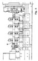
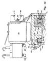
- the section on AA ( Figure 4) allows the two parallel spaced apart rails 66, 68 to be seen (in cross section) on which the workrest carriage 43 slides by means of linear bearings 70, 72. Also visible in cross-section is the end spacer 37. Fluid connections are shown at 74, 76 by which air or hydraulic fluid is conveyed to and from the workrest to drive the jaws 44, 46 in and out of the workrest housing, in the directions indicated by the arrow 78.
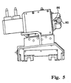
- the section on BB ( Figure 5) shows the engagement of a cylindrical workpiece region 80 by the upper and lower jaws 82, 84 and an intermediate stop 86.
- the latter is that part of the workrest which provides the reaction to the grinding forces exerted by the grinding wheel on the workpiece.
- Each pair of jaws of each of the workrests includes a step such as 86 shown in Figure 5.
- FIG. 3 The rear view on arrow "C" in Figure 3 and which comprises Figure 6, shows how a machined setting up bar 88 can be fitted between headstock and tailstock preparatory to the replacement of a camshaft workpiece.
- This allows the workrest positions to be checked and the computer control system (item 90 in Figure 1) to be initialised with position information relating to the workrest jaws, to allow the latter to be advanced as required during grinding to just the correct positions to engage similar cylindrical regions of a camshaft.
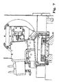
- Figure 7 shows how the rails 66, 68 are screwed to the workslide 12 as by screw 92.
- each assembly has a plate at each end for attachment to the opposed end faces of adjacent workrest carriages or the headstock or tailstock.
- One such bellows endplate is shown at 94 in Figure 8. This is in fact an end plate of the bellows which fits between the end face of the headstock carriage 96 (also denoted in Figure 2), and the opposed end face of the workrest carriage 37 (not shown in Figure 8), below spacer 50. Pairs of screws or rivets designated 98 and 100, secure the bellows endplate to the headstock end face 96.
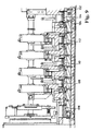
- Figure 9 is an enlarged scale section through the front rail 68 shown secured in place by a plurality of screws 102, 104 etc.
- the bellows described with reference to Figure 8 can here be seen at 106, 108, 110, 112 and 114.
- the bellows assemblies further seal the sliding surfaces of the rails and linear bearings against swarf and other grinding media.
- the cover-spacers may be sealed longitudinally to surfaces of the rail supporting structure as well as being sealed against the end faces of the workrests (or workrest carriages) and the headstock and tailstock housings.
- Figure 10 is similar to Figure 5, and shows a proprietary workrest 116 with work engaging jaws 118, 120 and 122, mounted on a carriage generally designated 124.
- the carriage runs on two rails 126 and 128 the cross-section of each of which is similar to an I-beam and the enlarged upper and lower sections are jointed by a narrow vertical stem and the shoulders of the upper and lower regions taper to the stem to provide linear inclined faces such as 130 and 132 in the case of rail 128.
- Complementary inclined bearing surfaces are provided by four rows of cylindrical rollers 133 in a roller bearing assembly such as 134 secured to the underside of the carriage 124.
- the inside faces 136, 138 of the other rail are similarly engaged by a slider generally designated 140, and its outer inclined faces are engaged by correspondingly inclined faces of a clamping member 142 of generally C cross-section, the upper end 144 of which is received in a parallel slided slot 146 for locating the member 142 relative to the carriage 124.
- the lower end generally designated 148 can be urged into engagement with the opposite inclined faces 150 and 152 of the rail 126 by screwing in a threaded bolt 154 the head of which forces the clamping device 142 into engagement at one end with the slot 146 and at its lower end with the inclined faces 150 and 152.
- the clamping so effected not only restricts the tendency for the carriage 124 to slide along the rails 126 and 128, but also removes any tendency for the carriage 124 to rock about either of the rails.
- the clamping action therefore restricts swaying or rocking of the carriage 124 relative to the rails, and particularly restricts rocking movement about the rail 128 in a plane perpendicular to the rails (ie within the plane of the sheet containing Figure 10).
- the slide 140 conventionally comprises one half of a roller bearing assembly similar to item 134 as provided for running on the front rail 128.
Landscapes
- Engineering & Computer Science (AREA)
- Mechanical Engineering (AREA)
- Grinding Of Cylindrical And Plane Surfaces (AREA)
- Constituent Portions Of Griding Lathes, Driving, Sensing And Control (AREA)
- Machine Tool Units (AREA)
Claims (23)
- Machine à rectifier comprenant une structure support fixe, un ensemble de tête de rectification (30) portant une meule (28) et pouvant coulisser par rapport à ladite structure dans un sens perpendiculaire à un axe de la pièce de travail, des moyens de poupée fixe (16) et de poupée mobile (20) montés sur la structure pour faire tourner une pièce de travail composite montée entre elles autour dudit axe de la pièce de travail, un support (36, 38, 40, 42) réglable par coulissement le long d'un élément allongé rigide placé au-dessous et qui s'étend sensiblement parallèlement à l'axe de la pièce de travail, un moyen de commande programmable à base d'ordinateur destiné à commander le mouvement de la tête de rectification, la rotation de la pièce de travail, la prise et le dégagement du support avec une région cylindrique de la pièce de travail, des moyens de fixation (60, 64) pour fixer le support au niveau d'un emplacement axial sélectionné le long de la longueur de l'élément allongé de façon que le support soit aligné avec ladite région cylindrique de la pièce de travail, caractérisé par des moyens de couvercle (50, 52, 54, 56, 58) pouvant être mis en prise avec le support sur les côtés opposés de celui-ci pour garder tout matériau indésirable hors de la surface de l'élément allongé en dessous et d'empêcher le mouvement latéral du support par rapport à son emplacement sélectionné.
- Machine selon la revendication 1, dans laquelle le support et le moyen de couvercle forment un roulement linéaire avec l'élément allongé.
- Machine selon la revendication 1 ou 2, dans laquelle l'élément allongé est constitué de deux rails parallèles espacés.
- Machine selon la revendication 2, dans laquelle chacun des moyens de couvercle est rigide et soit de longueur réglable, soit disponible en différentes longueurs pour permettre de couvrir par les couvercles des espaces de tailles différentes, mesurées parallèlement à l'axe de la pièce de travail, en fonction de l'emplacement sélectionné du support.
- Machine selon la revendication 4, dans laquelle les moyens de couvercles sont bridés axialement de façon à brider entre eux le support et à positionner le support le long de l'axe de la pièce de travail.
- Machine selon la revendication 4 ou la revendication 5 et comprenant de plus des couvercles télescopiques prévus entre les moyens de couvercle rigides et l'élément allongé et qui assurent l'étanchéité au niveau des extrémités respectives sur les côtés opposés du support et qui soit s'étendent axialement le long de la longueur du rail allongé pour empêcher l'intrusion de particules ou de matériaux fluides indésirables, soit assurent l'étanchéité au niveau de leurs extrémités opposées avec les faces d'extrémité des éléments supports entre lesquelles le rail allongé s'étend, ce qui a pour effet de former une enceinte étanche à l'intérieur de laquelle le rail allongé est protégé.
- Machine selon la revendication 6, dans laquelle les couvercles télescopiques sont sous la forme de soufflets qui peuvent s'allonger ou se contracter pour accepter le mouvement axial du support le long de l'élément allongé.
- Machine selon l'une quelconque des revendications 1 à 7, comprenant une pluralité d'autres supports montés le long de l'élément allongé pour se positionner contre les autres régions cylindriques d'une pièce de travail composite, de telle façon que lorsqu'on rectifie les autres régions cylindriques, elles peuvent être prises par un support pour résister aux déformations latérales de la pièce de travail lorsque la meule est forcée contre une région de la pièce de travail qui est diamétralement opposée à l'un des autres supports pour rectifier les régions particulières de celle-ci.
- Machine selon l'une quelconque des revendications 1 à 8, dans laquelle les moyens de couvercle et le(s) support(s) forment une pile horizontale et une force axiale est appliquée à la pile horizontale au moyen d'un élément de poussée agissant par l'intermédiaire de la poupée mobile de façon à brider la pile contre une face de la poupée fixe ou d'une structure associée à la poupée fixe ou en formant une partie.
- Machine selon l'une quelconque des revendications 1 à 9, dans laquelle le support comprend un carter qui peut coulisser le long de l'élément allongé et qui peut être bridé en position et des mors que l'on peut faire avancer et reculer par rapport au carter pour mettre en prise une région d'une pièce de travail.
- Machine selon la revendication 10, dans laquelle la pièce de travail est adaptée pour être en compression axiale indépendamment des forces de compression axiale agissant sur la pile horizontale et un carter auxiliaire contenant la contre-pointe de la poupée mobile est monté de manière coulissante et réglable sur la poupée mobile principale qui met en prise la pile.
- Machine selon la revendication 11 dépendant de la revendication 3, dans laquelle le moyen de bridage peut être engagé entre le support et un des rails, le moyen de bridage étant rendu effectif après que l'on a fait coulisser le support dans un emplacement sélectionné le long des rails afin de retenir le support dans cette position pendant l'opération d'usinage.
- Machine selon la revendication 11, dans laquelle un premier des deux rails allongés est sous-jacent aux mors du support et un deuxième rail est sous-jacent de l'autre côté du support, le moyen de bridage mettant en prise le deuxième rail.
- Machine selon la revendication 12, dans laquelle un premier ensemble de roulement est prévu au-dessous des mors du support afin de circuler sur le premier rail.
- Machine selon la revendication 13 ou la revendication 14, dans laquelle un deuxième ensemble de roulement est prévu pour mettre en prise un côté du deuxième rail et un élément mobile est fixé de manière réglable au support afin de mettre en prise le côté opposé du rail arrière et un moyen de bridage est prévu pour serrer l'élément mobile contre le rail arrière afin de brider le support sur le rail.
- Procédé de réglage d'une machine à rectifier selon l'une quelconque des revendications 1 à 15, dans lequel la pièce de travail composite est remplacée par une barre de réglage comportant au moins une région cylindrique usinée tout au long, de diamètre, étendue axiale et position axiale correspondant à la région cylindrique de la pièce de travail qui doit être rectifiée, et un support est positionné à la fois radialement et axialement le long de ladite barre de façon à être positionné pour mettre en prise des pièces de travail similaires lorsqu'elles sont chargées successivement sur la machine.
- Procédé de rectification d'une pièce de travail composite sur une machine à rectifier selon l'une quelconque des revendications 1 à 15, dans lequel les régions cylindriques de la pièce de travail doivent tout d'abord être rectifiées, et après qu'on a fini de rectifier au moins la première desdites régions cylindriques, un support est mis en prise avec elle, positionné le long de la longueur de l'axe de la pièce de travail, et après que les régions cylindriques de la pièce de travail composite ont toutes été rectifiées, on modifie la commande de la meule et on rectifie tour à tour chaque région non cylindrique de la pièce de travail, le support restant en position contre la première des régions cylindriques de la pièce de travail qui doit être rectifiée pendant toutes les opérations de rectification suivantes de la pièce de travail.
- Machine selon l'une quelconque des revendications 1 à 15, dans laquelle les pièces de travail composites qui doivent être rectifiées sont soit creuses soit présentent des extrémités creuses, les contre-pointes de la poupée fixe et de la poupée mobile sont sous la forme de dispositifs de prise de pièces de travail coniques et l'entraínement est transmis à la pièce de travail au moyen d'une liaison positive.
- Machine selon l'une quelconque des revendications 1 à 15, comprenant de plus des moyens pour procurer une force de compression axiale entre la poupée fixe, la pièce de travail et la poupée mobile, et un ajustement à friction entre une pointe entraínée au niveau de la poupée fixe et une extrémité de la pièce de travail en prise sur elle.
- Machine selon la revendication 19, dans laquelle ladite pointe entraínée comprend un cône d'entraínement dont la surface est imprégnée de poussière de diamant pour se mettre en prise dans une ouverture circulaire centrale dans ladite extrémité de la pièce de travail, et dans laquelle la force de compression axiale exercée entre la pièce et les pointes au niveau des extrémités opposées de la pièce de travail est suffisante pour amener la poussière à mordre la surface d'extrémité du matériau de la pièce de travail et la centrer avec précision et résister à tout mouvement relatif entre la pièce de travail et le cône d'entraínement.
- Machine selon l'une quelconque des revendications 18 à 20, dans laquelle la pièce de travail soit incorpore une marque d'indexage qui peut être détectée au moyen d'un dispositif de détection associé à la machine à rectifier pour délivrer un signal d'indexage au moyen de commande programmable, soit un dispositif d'indexage par encoche en V est prévu sous la commande du moyen de commande programmable qui, après que les régions cylindriques aient été rectifiées, est avancé pour se mettre en prise autour d'une région non cylindrique de la pièce de travail, et après avoir centré le composant par rapport à l'encoche procure une position zéro pour un dispositif d'indexage rotatif associé à l'entraínement de la pièce de travail afin de permettre ensuite l'indexage précis de la pièce de travail sous la commande par ordinateur, afin de présenter d'abord une et ensuite une autre des régions non cylindriques pour rectification.
- Machine selon l'une quelconque des revendications 1 à 15 ou 18 à 21, dans laquelle un moyen est prévu pour indexer l'ensemble de la tête de rectification par rapport à la pièce de travail ou la pièce de travail par rapport à l'ensemble de la tête de rectification, de façon à permettre à la meule de traiter différentes régions de la pièce de travail à la demande.
- Machine selon l'une quelconque des revendications 1 à 15 ou 18 à 22, comprenant de plus de multiples meules permettant de rectifier simultanément deux ou plusieurs régions de la pièce de travail.
Applications Claiming Priority (5)
| Application Number | Priority Date | Filing Date | Title |
|---|---|---|---|
| GB9813777 | 1998-06-25 | ||
| GBGB9813777.1A GB9813777D0 (en) | 1998-06-25 | 1998-06-25 | Improvements in and relating to grinding composite workpieces |
| GBGB9909891.5A GB9909891D0 (en) | 1999-04-30 | 1999-04-30 | Improvements in and relating to grinding composite workpieces |
| GB9909891 | 1999-04-30 | ||
| PCT/GB1999/001906 WO1999067055A1 (fr) | 1998-06-25 | 1999-06-16 | Appareil et procede de rectification de pieces composites |
Publications (2)
| Publication Number | Publication Date |
|---|---|
| EP1121223A1 EP1121223A1 (fr) | 2001-08-08 |
| EP1121223B1 true EP1121223B1 (fr) | 2002-12-18 |
Family
ID=26313931
Family Applications (1)
| Application Number | Title | Priority Date | Filing Date |
|---|---|---|---|
| EP99926621A Expired - Lifetime EP1121223B1 (fr) | 1998-06-25 | 1999-06-16 | Appareil et procede de rectification de pieces composites |
Country Status (8)
| Country | Link |
|---|---|
| US (1) | US6485353B1 (fr) |
| EP (1) | EP1121223B1 (fr) |
| CA (1) | CA2335626A1 (fr) |
| DE (1) | DE69904628T2 (fr) |
| ES (1) | ES2189429T3 (fr) |
| GB (1) | GB2338667B (fr) |
| MX (1) | MXPA00012909A (fr) |
| WO (1) | WO1999067055A1 (fr) |
Cited By (2)
| Publication number | Priority date | Publication date | Assignee | Title |
|---|---|---|---|---|
| CN104057388A (zh) * | 2014-06-27 | 2014-09-24 | 滨州泰源机械有限公司 | 曲轴抛光机 |
| CN112975600A (zh) * | 2021-03-17 | 2021-06-18 | 夏安东 | 一种快速水钻头抛光装置 |
Families Citing this family (12)
| Publication number | Priority date | Publication date | Assignee | Title |
|---|---|---|---|---|
| US20040244528A1 (en) * | 2001-09-27 | 2004-12-09 | Peter Meusburger | Camshaft and method for making same |
| BRPI0415289A (pt) * | 2004-05-22 | 2006-12-19 | Unova Uk Ltd | fuso de roda de retificação melhorada |
| DE102006008532A1 (de) | 2006-02-22 | 2007-08-30 | Thyssenkrupp Automotive Ag | Verfahren und Vorrichtung zur Fertigbearbeitung von gebauten Nocken- und Exzenterwellen |
| DE202006020697U1 (de) | 2006-05-13 | 2009-07-16 | Mahle International Gmbh | Nockenwelle mit geschliffenen Nockenprofilen |
| JP5054152B2 (ja) * | 2010-05-11 | 2012-10-24 | コマツNtc株式会社 | 研削盤 |
| CN108127559A (zh) * | 2017-12-19 | 2018-06-08 | 佛山市毅力机械制造有限公司 | 一种珠宝加工防护装置 |
| CN108527024B (zh) * | 2018-03-05 | 2019-08-09 | 山东科技大学 | 一种微型管棒材内外圆微磨削设备及磨削方法 |
| CN114310573B (zh) * | 2021-12-29 | 2023-07-04 | 厦门弘骏精密模具有限公司 | 一种注塑模具生产用加工设备 |
| CN114473700B (zh) * | 2022-02-25 | 2023-02-17 | 张悦鹏 | 一种自动化机械制造用毛刺去除装置 |
| CN115635374B (zh) * | 2022-12-24 | 2023-04-07 | 潍坊胜利石化机械有限公司 | 卧式机床曲轴加工用固定装置 |
| CN119017204B (zh) * | 2024-10-28 | 2025-03-11 | 江西佳时特数控股份有限公司 | 一种中凸工作台的磨削工装及工艺 |
| CN120269416A (zh) * | 2025-04-30 | 2025-07-08 | 东莞市博飞特模具有限公司 | 一种模具配件磨削装置 |
Family Cites Families (12)
| Publication number | Priority date | Publication date | Assignee | Title |
|---|---|---|---|---|
| US2744366A (en) * | 1952-09-18 | 1956-05-08 | Ewald A Arp | Steady rest |
| US3503156A (en) * | 1967-09-26 | 1970-03-31 | Engelberg Inc | Centerless grinding system |
| JPS5615966A (en) * | 1979-07-13 | 1981-02-16 | Toyoda Mach Works Ltd | Cam grinding machine |
| US5437125A (en) * | 1992-03-16 | 1995-08-01 | Barton, Ii; Kenneth A. | Surface polishing assembly |
| DE4329610C2 (de) * | 1993-09-02 | 1996-08-29 | Doerries Scharmann Gmbh | Bearbeitungszentrum für Kurbelwellen |
| GB2283192B (en) * | 1993-10-20 | 1997-07-16 | Western Atlas Uk Ltd | Improvements in and relating to grinding machines |
| GB9321639D0 (en) * | 1993-10-20 | 1993-12-08 | Litcom U K Limited | Improvements in and relating grinding machines |
| GB2289742B (en) * | 1994-05-27 | 1998-12-09 | Western Atlas Uk Ltd | Drive transmitting device |
| CA2221102A1 (fr) * | 1995-06-23 | 1997-01-09 | Western Atlas U.K. Limited | Ameliorations relatives au meulage |
| ES2141637B1 (es) * | 1996-04-02 | 2000-11-01 | Danobat | Cabezal pieza con desplazamiento lineal automatico para una rectificadora. |
| GB9615511D0 (en) * | 1996-07-24 | 1996-09-04 | Western Atlas Uk Ltd | Improvements relating to grinding methods and apparatus |
| US5975995A (en) * | 1997-06-25 | 1999-11-02 | Unova Ip Corp. | Machining apparatus and method |
-
1999
- 1999-06-16 MX MXPA00012909A patent/MXPA00012909A/es unknown
- 1999-06-16 GB GB9913891A patent/GB2338667B/en not_active Expired - Fee Related
- 1999-06-16 DE DE69904628T patent/DE69904628T2/de not_active Expired - Fee Related
- 1999-06-16 EP EP99926621A patent/EP1121223B1/fr not_active Expired - Lifetime
- 1999-06-16 WO PCT/GB1999/001906 patent/WO1999067055A1/fr not_active Ceased
- 1999-06-16 ES ES99926621T patent/ES2189429T3/es not_active Expired - Lifetime
- 1999-06-16 CA CA002335626A patent/CA2335626A1/fr not_active Abandoned
- 1999-07-16 US US09/720,109 patent/US6485353B1/en not_active Expired - Fee Related
Cited By (3)
| Publication number | Priority date | Publication date | Assignee | Title |
|---|---|---|---|---|
| CN104057388A (zh) * | 2014-06-27 | 2014-09-24 | 滨州泰源机械有限公司 | 曲轴抛光机 |
| CN104057388B (zh) * | 2014-06-27 | 2017-03-29 | 滨州泰源机械有限公司 | 曲轴抛光机 |
| CN112975600A (zh) * | 2021-03-17 | 2021-06-18 | 夏安东 | 一种快速水钻头抛光装置 |
Also Published As
| Publication number | Publication date |
|---|---|
| DE69904628T2 (de) | 2003-10-02 |
| GB2338667B (en) | 2000-11-08 |
| EP1121223A1 (fr) | 2001-08-08 |
| MXPA00012909A (es) | 2002-04-24 |
| WO1999067055A1 (fr) | 1999-12-29 |
| GB9913891D0 (en) | 1999-08-18 |
| GB2338667A (en) | 1999-12-29 |
| DE69904628D1 (de) | 2003-01-30 |
| CA2335626A1 (fr) | 1999-12-29 |
| ES2189429T3 (es) | 2003-07-01 |
| US6485353B1 (en) | 2002-11-26 |
Similar Documents
| Publication | Publication Date | Title |
|---|---|---|
| US6485353B1 (en) | Apparatus and method for grinding composite workpieces | |
| US5667432A (en) | Grinding machine | |
| CA2491686C (fr) | Procede et dispositif pour rectifier un element de machine a symetrie de revolution | |
| US8715036B2 (en) | Grinding center and method for the simultaneous grinding of multiple crankshaft bearings | |
| US5906534A (en) | Sharpening a knife blade | |
| US9108287B2 (en) | Method for grinding the main and rod bearing of a crankshaft by external cylindrical grinding | |
| RU2467863C2 (ru) | Шлифовальный центр и способ одновременного шлифования нескольких подшипников и концевых поверхностей коленчатых валов | |
| KR101487467B1 (ko) | 외부 원통 연삭에 의한 크랭크축의 메인 및 로드 베어링의 연삭 방법 및 이 방법을 수행하는 장치 | |
| KR100820985B1 (ko) | 크랭크샤프트의 중심 베어링 연삭방법과 장치 | |
| US6453528B1 (en) | Device and method for the machining of crankshaft pins | |
| US20080102736A1 (en) | Method For Machining Rotary Parts | |
| JPH05277913A (ja) | クランク軸におけるジャーナルの研削方法及び研削盤 | |
| US3864879A (en) | Cam grinding | |
| EP0846517B1 (fr) | Machine et procédé de meulage des manetons de vilebrequin | |
| CA2275457A1 (fr) | Machine amelioree pour microfinition | |
| KR100297270B1 (ko) | 복합가공장치 및 그 가공방법 | |
| US5865667A (en) | Grinding machine | |
| KR20170039239A (ko) | 공작물, 특히 크랭크 샤프트 또는 캠 샤프트를 마무리 가공하기 위한 피니싱 장치 | |
| CN115210042A (zh) | 导轨磨削装置、导轨的磨削方法以及导轨磨削装置的调整方法 | |
| JPS591553B2 (ja) | 心押台 | |
| JP2001170803A (ja) | 工作機械の心押台 | |
| US20060168814A1 (en) | Method and machine tool for machining a tire of a train wheel set | |
| US6134763A (en) | Combined machining apparatus for making piston rings | |
| EP0724500B1 (fr) | Machines a rectifier ameliorees | |
| US3138998A (en) | Surface finishing apparatus |
Legal Events
| Date | Code | Title | Description |
|---|---|---|---|
| PUAI | Public reference made under article 153(3) epc to a published international application that has entered the european phase |
Free format text: ORIGINAL CODE: 0009012 |
|
| 17P | Request for examination filed |
Effective date: 20010104 |
|
| AK | Designated contracting states |
Kind code of ref document: A1 Designated state(s): DE ES FR IT |
|
| GRAG | Despatch of communication of intention to grant |
Free format text: ORIGINAL CODE: EPIDOS AGRA |
|
| 17Q | First examination report despatched |
Effective date: 20020319 |
|
| GRAG | Despatch of communication of intention to grant |
Free format text: ORIGINAL CODE: EPIDOS AGRA |
|
| GRAH | Despatch of communication of intention to grant a patent |
Free format text: ORIGINAL CODE: EPIDOS IGRA |
|
| GRAH | Despatch of communication of intention to grant a patent |
Free format text: ORIGINAL CODE: EPIDOS IGRA |
|
| GRAA | (expected) grant |
Free format text: ORIGINAL CODE: 0009210 |
|
| AK | Designated contracting states |
Kind code of ref document: B1 Designated state(s): DE ES FR IT |
|
| REF | Corresponds to: |
Ref document number: 69904628 Country of ref document: DE Date of ref document: 20030130 Kind code of ref document: P Ref document number: 69904628 Country of ref document: DE Date of ref document: 20030130 |
|
| REG | Reference to a national code |
Ref country code: ES Ref legal event code: FG2A Ref document number: 2189429 Country of ref document: ES Kind code of ref document: T3 |
|
| ET | Fr: translation filed | ||
| PLBE | No opposition filed within time limit |
Free format text: ORIGINAL CODE: 0009261 |
|
| STAA | Information on the status of an ep patent application or granted ep patent |
Free format text: STATUS: NO OPPOSITION FILED WITHIN TIME LIMIT |
|
| 26N | No opposition filed |
Effective date: 20030919 |
|
| PGFP | Annual fee paid to national office [announced via postgrant information from national office to epo] |
Ref country code: FR Payment date: 20050617 Year of fee payment: 7 |
|
| PGFP | Annual fee paid to national office [announced via postgrant information from national office to epo] |
Ref country code: ES Payment date: 20050708 Year of fee payment: 7 |
|
| PGFP | Annual fee paid to national office [announced via postgrant information from national office to epo] |
Ref country code: DE Payment date: 20050801 Year of fee payment: 7 |
|
| PG25 | Lapsed in a contracting state [announced via postgrant information from national office to epo] |
Ref country code: ES Free format text: LAPSE BECAUSE OF NON-PAYMENT OF DUE FEES Effective date: 20060617 |
|
| PGFP | Annual fee paid to national office [announced via postgrant information from national office to epo] |
Ref country code: IT Payment date: 20060630 Year of fee payment: 8 |
|
| PG25 | Lapsed in a contracting state [announced via postgrant information from national office to epo] |
Ref country code: DE Free format text: LAPSE BECAUSE OF NON-PAYMENT OF DUE FEES Effective date: 20070103 |
|
| REG | Reference to a national code |
Ref country code: FR Ref legal event code: ST Effective date: 20070228 |
|
| REG | Reference to a national code |
Ref country code: ES Ref legal event code: FD2A Effective date: 20060617 |
|
| PG25 | Lapsed in a contracting state [announced via postgrant information from national office to epo] |
Ref country code: FR Free format text: LAPSE BECAUSE OF NON-PAYMENT OF DUE FEES Effective date: 20060630 |
|
| PG25 | Lapsed in a contracting state [announced via postgrant information from national office to epo] |
Ref country code: IT Free format text: LAPSE BECAUSE OF NON-PAYMENT OF DUE FEES Effective date: 20070616 |