EP1121729B1 - Systeme de connexion a axes multiples - Google Patents
Systeme de connexion a axes multiples Download PDFInfo
- Publication number
- EP1121729B1 EP1121729B1 EP00954193A EP00954193A EP1121729B1 EP 1121729 B1 EP1121729 B1 EP 1121729B1 EP 00954193 A EP00954193 A EP 00954193A EP 00954193 A EP00954193 A EP 00954193A EP 1121729 B1 EP1121729 B1 EP 1121729B1
- Authority
- EP
- European Patent Office
- Prior art keywords
- projections
- axis
- pair
- component
- feature
- Prior art date
- Legal status (The legal status is an assumption and is not a legal conclusion. Google has not performed a legal analysis and makes no representation as to the accuracy of the status listed.)
- Expired - Lifetime
Links
Images
Classifications
-
- H—ELECTRICITY
- H01—ELECTRIC ELEMENTS
- H01R—ELECTRICALLY-CONDUCTIVE CONNECTIONS; STRUCTURAL ASSOCIATIONS OF A PLURALITY OF MUTUALLY-INSULATED ELECTRICAL CONNECTING ELEMENTS; COUPLING DEVICES; CURRENT COLLECTORS
- H01R13/00—Details of coupling devices of the kinds covered by groups H01R12/70 or H01R24/00 - H01R33/00
- H01R13/62—Means for facilitating engagement or disengagement of coupling parts or for holding them in engagement
- H01R13/627—Snap or like fastening
- H01R13/6271—Latching means integral with the housing
- H01R13/6273—Latching means integral with the housing comprising two latching arms
-
- H—ELECTRICITY
- H01—ELECTRIC ELEMENTS
- H01R—ELECTRICALLY-CONDUCTIVE CONNECTIONS; STRUCTURAL ASSOCIATIONS OF A PLURALITY OF MUTUALLY-INSULATED ELECTRICAL CONNECTING ELEMENTS; COUPLING DEVICES; CURRENT COLLECTORS
- H01R2201/00—Connectors or connections adapted for particular applications
- H01R2201/26—Connectors or connections adapted for particular applications for vehicles
Definitions
- This invention relates to a connection system for a component, such as a sensor, which provides a restraining force on the component in three orthogonal directions, while centering the component in its mount and reducing vibration levels.
- the claimed invention provides an integral component connection system that restrains the component in three orthogonal directions, centers the component in its mounting location, and preferably absorbs vibration.
- the inventive connection system further preferably provides an audible or visible indication when the component is connected.
- the connection system of the present invention is preferably lightweight and easy to disengage, allowing for quick removal of the component for replacement or repair.
- the claimed invention provides a system for connecting a male member to a female member, the male and female members being relatively displaceable substantially along an axis lying in a plane.
- the system comprises a pair of first projections each extending parallel to the plane and each having a first end spaced from a second end, each first end being fixed to a first one of the male and female members, and each second end being resiliently movable with respect to the first member, each second end including a first one of a cavity feature and a protrusion feature; and a pair of grooves in a second one of the male and female members, each groove extending parallel to the axis and receiving a respective one of the pair of first projections, and each groove including a second one of the cavity feature and the protrusion feature, the second feature cooperatively engaging the first feature such that the first member is centered about the axis with respect to the second member and such that the first member is retained along the axis with respect to the second member.
- the claimed invention also provides a system for connecting a
- the system comprises a pair of first projections each extending parallel to the plane and each having a first end spaced from a second end, each first end being fixed to a first one of the male and female members, and each second end being resiliently movable with respect to the first member to preferably absorb relative vibration between the male and female members; a pair of grooves in a second one of the male and female members, each groove extending parallel to the axis and receiving a respective one of the pair of first projections; preferably a tip formed on each second end and an aperture extending from each groove through the second member, each tip tapering from a first size at least as large as its corresponding aperture to a second size smaller than the corresponding aperture, and each tip cooperatively engaging its corresponding aperture such that the first member is centered about the axis with respect to the second member and such that the first member is retained along the axis with respect to the second member; each tip being visible in its corresponding aperture when the first member is retained along the axis with respect to the second member and a pair of second
- the claimed invention also provides a method of connecting a male member to a female member, the male and female members being relatively displaceable substantially along an axis lying in a plane.
- the method comprises providing a first one of the male and female members with a pair of first projections each extending parallel to the plane and each having a first end spaced from a second end, each first end being fixed to the first member, and each second end being resiliently movable with respect to the first member, each second end including a first one of a cavity feature and a protrusion feature; providing a second one of the male and female members with a pair of grooves, each groove extending parallel to the axis and receiving a respective one of the pair of first projections, and each groove including a second one of the cavity feature and the protrusion feature; aligning the male member with respect to the female member along the axis such that each groove will receive a respective one of the pair of first projections; and relatively displacing the male member with respect to the female member until the second feature cooperatively engage
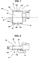
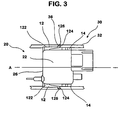
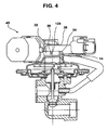
- Figures 1-3 illustrate a component incorporating the connection system according to the claimed invention.
- the inventive connection system utilizes two different types of projections 10 on the component 20 which interact with a retention surface 30 to removably secure the component 20 in place.
- the projections 10 are formed unitarily with the component housing 22.
- a projection assembly can be formed separately and added on to an existing component.
- the retention surface 30 comprises a pair of grooves 32, each formed with a channel 34 adapted to engage the projections 10.
- the retention surface 30 can comprise discrete channel sections.
- Figures 1 and 2 illustrate a component with projections 10 of the present invention unitarily formed with a housing.
- the component 20 shown is a pressure sensor 26 for an automotive exhaust gas recirculation (EGR) system module 40.
- EGR automotive exhaust gas recirculation
- the connection system according to the claimed invention could be utilized on a range of components of varying size and shape. Further, the inventive system could be made of a variety of materials, provided that the materials exhibited the requisite properties, such as weight, strength, and flexibility.
- a pair of first and second projections 12,14 are disposed on the component housing 22 in a substantially planar arrangement. The projections are arranged symmetrically about an axis A of the component 20, with the first projections 12 spaced from the second projections 14 along the axis A. While the invention is described as using pairs of projections 10, it is envisioned that its advantages could be achieved with a single first and second projection 12,14.
- the first projections 12 have a generally elongated shape, with a first end 122 secured to the component housing 22 and a second end 124 slightly offset from the housing 22. These projections 12 are resilient, so that if they are pressed towards the housing 22, they will be resiliently flex away from the housing 22.
- the second projections 14 may be generally rectangular in shape and are secured to the housing 22 along their length, making them essentially rigid.
- FIG 3 shows the component 20 secured with the connection system according to the claimed invention.
- the retention surface 30 in the illustrated embodiment comprises a pair of grooves 32, each having a C-shaped channel 34 along the length of an inner surface.
- the projections 12,14 and the channels 34 are dimensioned so that the projections 12,14 slidingly fit closely within the channels 34. Relative motion between the projections 12,14 and the grooves 32 is limited to sliding motion along the length of the channels 34.
- Each groove 32 has an aperture 36 for engaging a respective second end 124 of a first projection 12.
- the apertures 36 are located on the grooves 32 at a position corresponding to the mounting position of the component 20.
- the features of the grooves 32 are clearly shown in Figure 4, which shows the sensor 26 mounted on an automotive EGR system module (ESM) 40.
- ESM automotive EGR system module
- connection system will be described with reference to Figures 3 and 4.
- the component 20 to be mounted (in the illustrated example, a sensor 26) is oriented so that the first and second projections 12,14 are aligned with the channel 34 in each groove 32.
- the component 20 is then displaced along the axis in the connecting direction.
- the first projections 12 enter the respective channels 34, the second ends 124 of those projections 12 are forced inwardly.
- a tip, or angled section, 126 on each second end 124 eases the entry of the second ends 124 into the respective channels 34.
- the first projections 12 exert an outward biasing force on the grooves 32.
- the second projections 14 enter the channels 34.
- the component 20 is displaced until it has reached the desired mounting position.
- the second ends 124 of the first projections 12 snap outwardly into the apertures 36 in the respective grooves 32.
- the snap provides an audible indication that the component 20 is securely fixed.
- the appearance of the second ends 124 of the projections 12 in the notches 36 provides a visual indication that the component 20 is in place.
- the first and second projections 12,14 interact with the grooves 32 to provide a locking force on the component 20 in three orthogonal directions.
- the first projections 12 restrain movement along the axial direction by interacting with the apertures 36 in the grooves 32.
- the second projections 14 restrain movement in two opposite directions perpendicular to the plane (which includes the axis A) of the component 20.
- the restraining forces on the second projections 14 are generated by the interaction of the projections 14 with at least two contact surfaces of each channel 34.
- the resiliency of the first projections 12 provides the inventive connection system with several additional advantages. Because the spring force of each of the first projections 12 is approximately equal, the projections 12 act to maintain the component 20 in a centered position between the grooves 32. This self-centering feature greatly simplifies installation. Further, due to their flexibility, the first projections 12 serve to reduce the vibration levels encountered by the component 20. Lower vibration levels contribute significantly to a longer operational life for most components.
- connection system of the present invention allows for quick removal of components.
- the second ends 124 of the first projections 12 are pressed into the apertures 36 on each groove 32 while the component 20 is pulled in a direction opposite to the mounting direction.
- the first and second projections 12,14 can slide along the channels 34 until the component 20 is removed. Easy mounting and removal facilitates assembly of a device, as well as repair and replacement of individual components.
Landscapes
- Vibration Prevention Devices (AREA)
- Details Of Connecting Devices For Male And Female Coupling (AREA)
- Use Of Switch Circuits For Exchanges And Methods Of Control Of Multiplex Exchanges (AREA)
Claims (11)
- Système permettant de connecter un organe mâle (20) à un organe femelle (30), les organes mâle et femelle étant relativement mobiles sensiblement le long d'un axe (A) s'étendant dans un plan, le système comprenant :une paire de premières saillies (12) s'étendant chacune parallèlement au plan et ayant chacune une première extrémité (122) espacée d'une seconde extrémité (124), chaque première extrémité étant fixée à un premier organe parmi les organes mâle et femelle et chaque seconde extrémité étant mobile de manière résiliente par rapport au premier organe, chaque seconde extrémité comprenant un premier élément parmi un élément formant cavité (36) et un élément formant saillie (126) ; etune paire de rainures (32) dans un second organe parmi les organes mâle et femelle, chaque rainure s'étendant parallèlement à l'axe et étant conçue pour recevoir une saillie respective de la paire de premières saillies et chaque rainure comprenant un second élément parmi l'élément formant cavité et l'élément formant saillie, le second élément étant conçu pour se solidariser par coopération avec le premier élément d'une manière telle que le premier organe est centré autour de l'axe par rapport au second organe et telle que le premier organe est maintenu le long de l'axe par rapport au second organe ; caractérisé en ce queau moins une seconde saillie est fixée au premier organe et s'étend parallèlement au plan, chaque seconde saillie ayant au moins deux faces se solidarisant par coulissement avec le second organe ; etau moins une des rainures comprend au moins deux surfaces en vis-à-vis des faces respectives des au moins deux faces et empêche un déplacement relatif des premier et second organes perpendiculairement au plan.
- Système selon la revendication 1, dans lequel il existe une paire de secondes saillies, chacune des secondes saillies se solidarisant par coulissement avec les faces respectives d'une rainure correspondante de la paire de rainures.
- Système selon la revendication 2, dans lequel la paire de premières saillies, la paire de rainures et la paire de secondes saillies s'étendent communément dans le plan.
- Système selon la revendication 1, dans lequel chaque seconde saillie est fixée de manière sensiblement rigide au premier organe.
- Système selon la revendication 1, dans lequel chaque rainure comprend un profil globalement en forme de C s'ouvrant vers l'axe.
- Système selon la revendication 1, dans lequel chaque seconde extrémité mobile de manière résiliente absorbe une vibration relative entre les premier et second organes.
- Système selon la revendication 1, dans lequel l'élément formant cavité comprend une ouverture s'étendant depuis chaque rainure à travers le second organe et l'élément formant saillie comprend une pointe de chaque seconde extrémité.
- Système selon la revendication 7, dans lequel la pointe de chaque seconde extrémité est visible dans l'ouverture de chaque rainure quand le premier organe est maintenu le long de l'axe par rapport au second organe.
- Système selon la revendication 7, dans lequel la pointe de chaque seconde extrémité se rétrécit depuis une première taille au moins aussi grande que son ouverture correspondante jusqu'à une seconde taille inférieure à l'ouverture correspondante.
- Procédé permettant de connecter un organe mâle à un organe femelle, les organes mâle et femelle étant relativement mobiles sensiblement le long d'un axe s'étendant dans un plan, le procédé comprenant les étapes consistant à ;doter un premier organe parmi les organes mâle et femelle d'une paire de premières saillies s'étendant chacune parallèlement au plan et ayant chacune une première extrémité espacée d'une seconde extrémité, chaque première extrémité étant fixée au premier organe et chaque seconde extrémité étant mobile de manière résiliente par rapport au premier organe, chaque seconde extrémité comprenant un premier élément parmi un élément formant cavité et un élément formant saillie ;doter un second organe parmi les organes mâle et femelle d'une paire de rainures, chaque rainure s'étendant parallèlement à l'axe et recevant une saillie respective de la paire de premières saillies et chaque rainure comprenant un second élément parmi l'élément formant cavité et l'élément formant saillie ;aligner l'organe mâle par rapport à l'organe femelle le long de l'axe d'une manière telle que chaque rainure recevra une saillie de la paire de premières saillies ; etdéplacer relativement l'organe mâle par rapport à l'organe femelle jusqu'à ce que le second élément se solidarise par coopération avec le premier élément d'une manière telle quele premier organe est centré autour de l'axe par rapport au second organe,le premier organe est maintenu le long de l'axe par rapport au second organe, etune vibration relative entre les premier et second organes est absorbée, etdoter le premier organe d'une paire de secondes saillies s'étendant parallèlement au plan, chaque seconde saillie ayant au moins deux faces en face du second organe ;dans lequel l'étape de déplacement relatif consiste en ce que les au moins deux faces d'une des saillies se solidarisent par coulissement avec des surfaces respectives de la rainure d'une manière telle que les premier et second organes ne peuvent pas effectuer de déplacement relatif perpendiculairement au plan.
- Procédé selon la revendication 10, dans lequel l'élément formant saillie est visible dans l'élément formant cavité quand le premier organe est maintenu le long de l'axe par rapport au second organe.
Applications Claiming Priority (3)
| Application Number | Priority Date | Filing Date | Title |
|---|---|---|---|
| US14904199P | 1999-08-16 | 1999-08-16 | |
| US149041P | 1999-08-16 | ||
| PCT/CA2000/000934 WO2001013472A1 (fr) | 1999-08-16 | 2000-08-16 | Systeme de connexion a axes multiples |
Publications (2)
| Publication Number | Publication Date |
|---|---|
| EP1121729A1 EP1121729A1 (fr) | 2001-08-08 |
| EP1121729B1 true EP1121729B1 (fr) | 2007-10-10 |
Family
ID=22528540
Family Applications (1)
| Application Number | Title | Priority Date | Filing Date |
|---|---|---|---|
| EP00954193A Expired - Lifetime EP1121729B1 (fr) | 1999-08-16 | 2000-08-16 | Systeme de connexion a axes multiples |
Country Status (4)
| Country | Link |
|---|---|
| EP (1) | EP1121729B1 (fr) |
| AT (1) | ATE375611T1 (fr) |
| DE (1) | DE60036684T2 (fr) |
| WO (1) | WO2001013472A1 (fr) |
Families Citing this family (3)
| Publication number | Priority date | Publication date | Assignee | Title |
|---|---|---|---|---|
| US9598787B2 (en) | 2013-03-14 | 2017-03-21 | Rohm And Haas Electronic Materials Llc | Method of filling through-holes |
| US10512174B2 (en) | 2016-02-15 | 2019-12-17 | Rohm And Haas Electronic Materials Llc | Method of filling through-holes to reduce voids and other defects |
| US10508357B2 (en) | 2016-02-15 | 2019-12-17 | Rohm And Haas Electronic Materials Llc | Method of filling through-holes to reduce voids and other defects |
Family Cites Families (5)
| Publication number | Priority date | Publication date | Assignee | Title |
|---|---|---|---|---|
| US3569909A (en) * | 1968-12-26 | 1971-03-09 | Amp Inc | Electrical connector assembly having improved latching means |
| JPH01132076U (fr) * | 1988-03-04 | 1989-09-07 | ||
| DK163853C (da) * | 1988-12-23 | 1992-08-31 | Knudsen Nordisk Elect | Stikindsats og plade med udskaering til denne stikindsats til brug ved montering af elektriske stik |
| NL8902192A (nl) * | 1989-08-30 | 1991-03-18 | Du Pont Nederland | Inbouwconnector voorzien van een vergrendelframe. |
| JP3200546B2 (ja) * | 1995-09-04 | 2001-08-20 | 矢崎総業株式会社 | 可動コネクタ |
-
2000
- 2000-08-16 AT AT00954193T patent/ATE375611T1/de not_active IP Right Cessation
- 2000-08-16 WO PCT/CA2000/000934 patent/WO2001013472A1/fr not_active Ceased
- 2000-08-16 DE DE60036684T patent/DE60036684T2/de not_active Expired - Lifetime
- 2000-08-16 EP EP00954193A patent/EP1121729B1/fr not_active Expired - Lifetime
Non-Patent Citations (1)
| Title |
|---|
| None * |
Also Published As
| Publication number | Publication date |
|---|---|
| DE60036684T2 (de) | 2008-12-04 |
| WO2001013472A1 (fr) | 2001-02-22 |
| ATE375611T1 (de) | 2007-10-15 |
| EP1121729A1 (fr) | 2001-08-08 |
| DE60036684D1 (de) | 2007-11-22 |
Similar Documents
| Publication | Publication Date | Title |
|---|---|---|
| CN113043906B (zh) | 一种换电式纯电动重卡换电系统结构 | |
| EP2526746B1 (fr) | Dispositif de retenue de carte à circuit imprimé à base de coins | |
| US7992950B2 (en) | Method for installing a slide assembly for a computer server using dual flat springs | |
| US4978313A (en) | Movable connector | |
| US5407297A (en) | Circuit board retainer having a spring body member | |
| US20010002344A1 (en) | Method for mounting a connector on a panel and a connector assembly | |
| DE102017209584A1 (de) | Anbringungs-Struktur für einen Elektronikaufnahmekasten | |
| CN217957541U (zh) | 一种din导轨卡扣装置 | |
| US11431055B2 (en) | Battery pack | |
| US6755684B1 (en) | Multiple axis connection system | |
| EP1121729A1 (fr) | Systeme de connexion a axes multiples | |
| EP1968084B1 (fr) | Appareil pour la connexion d'un axe de liaison de disjoncteur | |
| EP2111674B1 (fr) | Système de connecteur à boîtier confiné | |
| EP4194243B1 (fr) | Port de charge d'un véhicule hybride ou électrique | |
| CN212300069U (zh) | 卡槽结构、安装框架及冷却装置 | |
| CN111913537B (zh) | 服务器 | |
| CN222513903U (zh) | 一种电子设备 | |
| KR970018862A (ko) | 연장 지지판을 가지고 있는 가동 커넥터 | |
| CN224243737U (zh) | 闸机立柱及闸机 | |
| US7527129B2 (en) | Brake carrier having improved electromechanical actuator and mounting arrangement therefor | |
| CN210859424U (zh) | 一种钢材精准安装加速装置 | |
| CN113320373B (zh) | 固定组件、电池包组件以及车辆 | |
| US20260002557A1 (en) | Tolerance Compensation Device and Tolerance Compensation Assembly | |
| CN221997092U (zh) | 一种磁性插扣及背带 | |
| CN108437749B (zh) | 回风框锁定装置、车用空调回风框组件和车用空调 |
Legal Events
| Date | Code | Title | Description |
|---|---|---|---|
| PUAI | Public reference made under article 153(3) epc to a published international application that has entered the european phase |
Free format text: ORIGINAL CODE: 0009012 |
|
| 17P | Request for examination filed |
Effective date: 20010319 |
|
| AK | Designated contracting states |
Kind code of ref document: A1 Designated state(s): AT BE CH CY DE DK ES FI FR GB GR IE IT LI LU MC NL PT SE |
|
| RAP1 | Party data changed (applicant data changed or rights of an application transferred) |
Owner name: SIEMENS VDO AUTOMOTIVE INC. |
|
| 17Q | First examination report despatched |
Effective date: 20061108 |
|
| GRAP | Despatch of communication of intention to grant a patent |
Free format text: ORIGINAL CODE: EPIDOSNIGR1 |
|
| GRAS | Grant fee paid |
Free format text: ORIGINAL CODE: EPIDOSNIGR3 |
|
| GRAA | (expected) grant |
Free format text: ORIGINAL CODE: 0009210 |
|
| AK | Designated contracting states |
Kind code of ref document: B1 Designated state(s): AT BE CH CY DE DK ES FI FR GB GR IE IT LI LU MC NL PT SE |
|
| REG | Reference to a national code |
Ref country code: GB Ref legal event code: FG4D |
|
| REG | Reference to a national code |
Ref country code: CH Ref legal event code: EP |
|
| REG | Reference to a national code |
Ref country code: IE Ref legal event code: FG4D |
|
| REF | Corresponds to: |
Ref document number: 60036684 Country of ref document: DE Date of ref document: 20071122 Kind code of ref document: P |
|
| ET | Fr: translation filed | ||
| REG | Reference to a national code |
Ref country code: SE Ref legal event code: TRGR |
|
| NLV1 | Nl: lapsed or annulled due to failure to fulfill the requirements of art. 29p and 29m of the patents act | ||
| PG25 | Lapsed in a contracting state [announced via postgrant information from national office to epo] |
Ref country code: NL Free format text: LAPSE BECAUSE OF FAILURE TO SUBMIT A TRANSLATION OF THE DESCRIPTION OR TO PAY THE FEE WITHIN THE PRESCRIBED TIME-LIMIT Effective date: 20071010 Ref country code: CH Free format text: LAPSE BECAUSE OF FAILURE TO SUBMIT A TRANSLATION OF THE DESCRIPTION OR TO PAY THE FEE WITHIN THE PRESCRIBED TIME-LIMIT Effective date: 20071010 Ref country code: LI Free format text: LAPSE BECAUSE OF FAILURE TO SUBMIT A TRANSLATION OF THE DESCRIPTION OR TO PAY THE FEE WITHIN THE PRESCRIBED TIME-LIMIT Effective date: 20071010 Ref country code: ES Free format text: LAPSE BECAUSE OF FAILURE TO SUBMIT A TRANSLATION OF THE DESCRIPTION OR TO PAY THE FEE WITHIN THE PRESCRIBED TIME-LIMIT Effective date: 20080121 |
|
| REG | Reference to a national code |
Ref country code: CH Ref legal event code: PL |
|
| PG25 | Lapsed in a contracting state [announced via postgrant information from national office to epo] |
Ref country code: PT Free format text: LAPSE BECAUSE OF FAILURE TO SUBMIT A TRANSLATION OF THE DESCRIPTION OR TO PAY THE FEE WITHIN THE PRESCRIBED TIME-LIMIT Effective date: 20080310 |
|
| PG25 | Lapsed in a contracting state [announced via postgrant information from national office to epo] |
Ref country code: AT Free format text: LAPSE BECAUSE OF FAILURE TO SUBMIT A TRANSLATION OF THE DESCRIPTION OR TO PAY THE FEE WITHIN THE PRESCRIBED TIME-LIMIT Effective date: 20071010 |
|
| PG25 | Lapsed in a contracting state [announced via postgrant information from national office to epo] |
Ref country code: DK Free format text: LAPSE BECAUSE OF FAILURE TO SUBMIT A TRANSLATION OF THE DESCRIPTION OR TO PAY THE FEE WITHIN THE PRESCRIBED TIME-LIMIT Effective date: 20071010 |
|
| PLBE | No opposition filed within time limit |
Free format text: ORIGINAL CODE: 0009261 |
|
| STAA | Information on the status of an ep patent application or granted ep patent |
Free format text: STATUS: NO OPPOSITION FILED WITHIN TIME LIMIT |
|
| PG25 | Lapsed in a contracting state [announced via postgrant information from national office to epo] |
Ref country code: BE Free format text: LAPSE BECAUSE OF FAILURE TO SUBMIT A TRANSLATION OF THE DESCRIPTION OR TO PAY THE FEE WITHIN THE PRESCRIBED TIME-LIMIT Effective date: 20071010 |
|
| 26N | No opposition filed |
Effective date: 20080711 |
|
| PG25 | Lapsed in a contracting state [announced via postgrant information from national office to epo] |
Ref country code: GR Free format text: LAPSE BECAUSE OF FAILURE TO SUBMIT A TRANSLATION OF THE DESCRIPTION OR TO PAY THE FEE WITHIN THE PRESCRIBED TIME-LIMIT Effective date: 20080111 |
|
| PG25 | Lapsed in a contracting state [announced via postgrant information from national office to epo] |
Ref country code: MC Free format text: LAPSE BECAUSE OF NON-PAYMENT OF DUE FEES Effective date: 20080831 |
|
| PG25 | Lapsed in a contracting state [announced via postgrant information from national office to epo] |
Ref country code: IE Free format text: LAPSE BECAUSE OF NON-PAYMENT OF DUE FEES Effective date: 20080818 Ref country code: CY Free format text: LAPSE BECAUSE OF FAILURE TO SUBMIT A TRANSLATION OF THE DESCRIPTION OR TO PAY THE FEE WITHIN THE PRESCRIBED TIME-LIMIT Effective date: 20071010 |
|
| PG25 | Lapsed in a contracting state [announced via postgrant information from national office to epo] |
Ref country code: FI Free format text: LAPSE BECAUSE OF FAILURE TO SUBMIT A TRANSLATION OF THE DESCRIPTION OR TO PAY THE FEE WITHIN THE PRESCRIBED TIME-LIMIT Effective date: 20071010 |
|
| PG25 | Lapsed in a contracting state [announced via postgrant information from national office to epo] |
Ref country code: LU Free format text: LAPSE BECAUSE OF NON-PAYMENT OF DUE FEES Effective date: 20080816 |
|
| PG25 | Lapsed in a contracting state [announced via postgrant information from national office to epo] |
Ref country code: IT Free format text: LAPSE BECAUSE OF NON-PAYMENT OF DUE FEES Effective date: 20080831 |
|
| PGFP | Annual fee paid to national office [announced via postgrant information from national office to epo] |
Ref country code: GB Payment date: 20120821 Year of fee payment: 13 Ref country code: SE Payment date: 20120821 Year of fee payment: 13 |
|
| PGFP | Annual fee paid to national office [announced via postgrant information from national office to epo] |
Ref country code: DE Payment date: 20120831 Year of fee payment: 13 Ref country code: FR Payment date: 20120906 Year of fee payment: 13 |
|
| REG | Reference to a national code |
Ref country code: SE Ref legal event code: EUG |
|
| GBPC | Gb: european patent ceased through non-payment of renewal fee |
Effective date: 20130816 |
|
| PG25 | Lapsed in a contracting state [announced via postgrant information from national office to epo] |
Ref country code: DE Free format text: LAPSE BECAUSE OF NON-PAYMENT OF DUE FEES Effective date: 20140301 Ref country code: SE Free format text: LAPSE BECAUSE OF NON-PAYMENT OF DUE FEES Effective date: 20130817 |
|
| REG | Reference to a national code |
Ref country code: DE Ref legal event code: R119 Ref document number: 60036684 Country of ref document: DE Effective date: 20140301 |
|
| REG | Reference to a national code |
Ref country code: FR Ref legal event code: ST Effective date: 20140430 |
|
| PG25 | Lapsed in a contracting state [announced via postgrant information from national office to epo] |
Ref country code: GB Free format text: LAPSE BECAUSE OF NON-PAYMENT OF DUE FEES Effective date: 20130816 |
|
| PG25 | Lapsed in a contracting state [announced via postgrant information from national office to epo] |
Ref country code: FR Free format text: LAPSE BECAUSE OF NON-PAYMENT OF DUE FEES Effective date: 20130902 |