EP1121891A2 - Kontrollvorrichtung, speziell für Reinigungsgeräte - Google Patents
Kontrollvorrichtung, speziell für Reinigungsgeräte Download PDFInfo
- Publication number
- EP1121891A2 EP1121891A2 EP01101654A EP01101654A EP1121891A2 EP 1121891 A2 EP1121891 A2 EP 1121891A2 EP 01101654 A EP01101654 A EP 01101654A EP 01101654 A EP01101654 A EP 01101654A EP 1121891 A2 EP1121891 A2 EP 1121891A2
- Authority
- EP
- European Patent Office
- Prior art keywords
- appliance
- handle
- control device
- transmitter
- receiver
- Prior art date
- Legal status (The legal status is an assumption and is not a legal conclusion. Google has not performed a legal analysis and makes no representation as to the accuracy of the status listed.)
- Withdrawn
Links
Images

Classifications
-
- A—HUMAN NECESSITIES
- A47—FURNITURE; DOMESTIC ARTICLES OR APPLIANCES; COFFEE MILLS; SPICE MILLS; SUCTION CLEANERS IN GENERAL
- A47L—DOMESTIC WASHING OR CLEANING; SUCTION CLEANERS IN GENERAL
- A47L9/00—Details or accessories of suction cleaners, e.g. mechanical means for controlling the suction or for effecting pulsating action; Storing devices specially adapted to suction cleaners or parts thereof; Carrying-vehicles specially adapted for suction cleaners
- A47L9/28—Installation of the electric equipment, e.g. adaptation or attachment to the suction cleaner; Controlling suction cleaners by electric means
- A47L9/2894—Details related to signal transmission in suction cleaners
-
- A—HUMAN NECESSITIES
- A47—FURNITURE; DOMESTIC ARTICLES OR APPLIANCES; COFFEE MILLS; SPICE MILLS; SUCTION CLEANERS IN GENERAL
- A47L—DOMESTIC WASHING OR CLEANING; SUCTION CLEANERS IN GENERAL
- A47L9/00—Details or accessories of suction cleaners, e.g. mechanical means for controlling the suction or for effecting pulsating action; Storing devices specially adapted to suction cleaners or parts thereof; Carrying-vehicles specially adapted for suction cleaners
- A47L9/28—Installation of the electric equipment, e.g. adaptation or attachment to the suction cleaner; Controlling suction cleaners by electric means
- A47L9/2857—User input or output elements for control, e.g. buttons, switches or displays
Definitions
- the present invention relates to a control device, particularly but not exclusively useful for appliances used in the field of domestic and/or industrial cleaning.
- a wide variety of models of cleaning appliance is currently commercially available, ranging from vacuum cleaners to steam cleaners, irons, combined appliances and others used for cleaning in the home and in public places, such as restaurants, industries, shopping centers, et cetera.
- a first construction type provides for a body of the appliance which accommodates the boiler and is extended, for steam dispensing, by means of a hose which ends, at its free end, with a handle which is adapted to control the movement of the possibly replaceable tool of the steam appliance.
- switches are accommodated at the handle and, by means of electrical connecting wires arranged inside the hose, are connected to an electric valve which in turn controls the flow of steam or other auxiliary functions.
- connection between the switches and the electric valve occurs substantially at the mains voltage (220 and 110 V) and therefore with considerable danger for the user.
- this first construction type besides still not ensuring perfect safety of the controls available to the user, leads to high manufacturing costs.
- a second construction type meant to obviate the drawbacks noted as regards the first construction type again provides for switches which are accommodated in the handle of the tool, but said switches are connected at low voltage (12-18 V) with an electronic board or simply with a transformer, accommodated inside the body of the appliance.
- a third recent type accommodates, inside the handle, a wheel which controls a cable which slides within a sheath which is in turn accommodated inside the steam connection hose.
- the cable reaches inside the body of the appliance, in which it controls the opening or closure of an electric valve.
- this third construction type obviates the problem of safety due to the circulation of electric current proximate to the handle, it has characteristics of poor reliability under prolonged and intense use; moreover, experience in the field has shown that it is awkward for the user.
- Another construction type provides for a pneumatic connection between a control located in the handle and a transducer located in the appliance body and preset to control the various functions thereof.
- Cleaning appliances particularly vacuum cleaners, have been recently devised which use an infrared remote control located in the handle and a receiver located in the appliance body.
- the aim of the present invention is to provide a control device, particularly for appliances used in the field of cleaning, which solves the above-noted drawbacks of conventional devices, particularly obviating completely the problem of user safety.
- an object of the present invention is to provide a control device which is constructively simple and adaptable to the various models of appliance currently provided for specific uses.
- Another object of the present invention is to provide a control device which can be operated easily and ergonomically by the user.
- Another object of the present invention is to provide a control device which leads to production costs and times which are competitive with respect to conventional devices.
- Another object of the present invention is to provide a control device which can be manufactured with known technologies.
- a control device particularly for appliances used in the field of domestic and/or industrial cleaning, characterized in that it comprises at least one signal transmitter which is removably located on the handle of the tool of the cleaning appliance and a receiver which is located on the appliance body and is connected to means for controlling the various functions of the appliance.
- the transmitter on the handle can be combined with a receiver and the receiver on the appliance body can be combined with a transmitter.
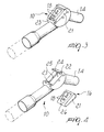
- a control device particularly for appliances used in the field of domestic and/or industrial cleaning, according to the invention, is generally designated by the reference numeral 10.
- the control device 10 in this case, is part of an appliance such as a vacuum cleaner, generally designated by the reference numeral 11 and provided with a body 12 which accommodates per se known suction means, not shown for the sake of simplicity, and to which a flexible hose 13 for the passage of the aspirated air is connected, in this case detachably; a handle 14 is fixed, likewise detachably, to the free end of the hose, and working tools, generally designated by the reference numeral 15, can be connected to the handle.
- an appliance such as a vacuum cleaner, generally designated by the reference numeral 11 and provided with a body 12 which accommodates per se known suction means, not shown for the sake of simplicity, and to which a flexible hose 13 for the passage of the aspirated air is connected, in this case detachably; a handle 14 is fixed, likewise detachably, to the free end of the hose, and working tools, generally designated by the reference numeral 15, can be connected to the handle.
- the control device 10 comprises a radio-wave transmitter 16 which is detachably arranged on the handle 14 and a receiver 17 which is arranged on the appliance body 12 and is connected to the means for controlling the various functions of the appliance, for example control switches, timers, power regulators, electronic boards, et cetera.
- the transmitter can be provided with various buttons 18, each for a specific function.
- the transmitter 16 is arranged inside a flat box-like body 21 which is separate from the handle 14 and is associated therewith by means of a detachable interlocking coupling.
- an end edge of the body 21 is in fact rounded in order to be accommodated in a hollow seat 22 of the handle.
- a flexible wing 23 which is hook-shaped and retains, by elastic deformation, the other edge by snap engagement.
- the surface 24 of the handle 14 on which the body 21 rests has a raised portion 25 which is adapted to be accommodated in a complementarily shaped seat 26 of the body 21.
- the raised portion 25 is perpendicular to the seat 22 and to the wing 23, so that a retention element is provided in all directions for the body 21.
- the device according to the invention fully solves the problem of user safety while ensuring easy use and structural strength.
- the noise produced by the vacuum will be less audible because of the insulation of the room.
- the appliance for hydromassage by connecting the delivery of the fan to the bathtub.
- the remote control allows to adjust all the functions in full safety, since there are no electrical connections.
- the removable transmitter can be particularly convenient for all those directional signals that cause problems in cleaning appliances in general because the body of the user is generally interposed between the handle and the appliance body.
- the transmitter By removing the transmitter, it can be orientated at will, regardless of the position of the handle with respect to the appliance body.
- transceivers can be used both on the appliance and on the handle.
- the status of the appliance can be transmitted to the body 21 and indicated by means of LEDs, displays, optical fibers, et cetera, so that the user can know the settings even remotely.
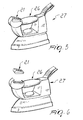
- Figures 5 and 6 further illustrate the case of a device according to the invention which is integrated in the handle 26 of an iron 27 which can be connected to the appliance.
- the materials and the dimensions may be any according to requirements.
Landscapes
- Engineering & Computer Science (AREA)
- Mechanical Engineering (AREA)
- Cleaning By Liquid Or Steam (AREA)
- Selective Calling Equipment (AREA)
- Electric Vacuum Cleaner (AREA)
- Vending Machines For Individual Products (AREA)
Applications Claiming Priority (2)
| Application Number | Priority Date | Filing Date | Title |
|---|---|---|---|
| ITPD20000030 IT1315384B1 (it) | 2000-02-01 | 2000-02-01 | Dispositivo di comando, particolarmente per apparecchi di puliziadomestica e/o industriale. |
| ITPD000030 | 2000-02-01 |
Publications (2)
| Publication Number | Publication Date |
|---|---|
| EP1121891A2 true EP1121891A2 (de) | 2001-08-08 |
| EP1121891A3 EP1121891A3 (de) | 2002-10-23 |
Family
ID=11451799
Family Applications (1)
| Application Number | Title | Priority Date | Filing Date |
|---|---|---|---|
| EP01101654A Withdrawn EP1121891A3 (de) | 2000-02-01 | 2001-01-26 | Kontrollvorrichtung, speziell für Reinigungsgeräte |
Country Status (2)
| Country | Link |
|---|---|
| EP (1) | EP1121891A3 (de) |
| IT (1) | IT1315384B1 (de) |
Cited By (7)
| Publication number | Priority date | Publication date | Assignee | Title |
|---|---|---|---|---|
| WO2004041052A1 (en) * | 2002-11-05 | 2004-05-21 | Aktiebolaget Electrolux | Vacuum cleaner control |
| EP1297777A3 (de) * | 2001-10-01 | 2006-04-26 | BSH Bosch und Siemens Hausgeräte GmbH | Vorrichtung zur Steuerung eines elektrischen Gerätes |
| EP2229857A3 (de) * | 2009-03-21 | 2015-05-06 | Festool GmbH | Sauggerät mit Funktionsmodul |
| EP3162263A1 (de) * | 2015-10-30 | 2017-05-03 | Vorwerk & Co. Interholding GmbH | Reinigungsgerät sowie vorsatzgerät zur verbindung mit einem basisgerät des reinigungsgerätes |
| DE102018108474A1 (de) * | 2018-04-10 | 2019-10-10 | Alfred Kärcher SE & Co. KG | Sauggerät mit Fernbedienung |
| EP4098169A1 (de) * | 2021-06-03 | 2022-12-07 | Seb S.A. | Schlittenstaubsauger mit handgriff, der mit einer fernbedienung ausgestattet ist |
| WO2025082786A1 (de) | 2023-10-18 | 2025-04-24 | Alfred Kärcher SE & Co. KG | Kombinierte dampferzeugungs- und dampfabgabevorrichtung |
Family Cites Families (3)
| Publication number | Priority date | Publication date | Assignee | Title |
|---|---|---|---|---|
| JP3818409B2 (ja) * | 1997-06-20 | 2006-09-06 | 東芝テック株式会社 | 電気掃除機 |
| DE19736595B4 (de) * | 1997-08-22 | 2007-04-12 | BSH Bosch und Siemens Hausgeräte GmbH | Drahtlose Fernbetätigungseinrichtung für einen Staubsauger |
| DE19902130A1 (de) * | 1998-01-23 | 1999-09-23 | Kwang Ju Electronics Co Ltd | Fernsteuervorrichtung eines Staubsaugers |
-
2000
- 2000-02-01 IT ITPD20000030 patent/IT1315384B1/it active
-
2001
- 2001-01-26 EP EP01101654A patent/EP1121891A3/de not_active Withdrawn
Cited By (12)
| Publication number | Priority date | Publication date | Assignee | Title |
|---|---|---|---|---|
| EP1297777A3 (de) * | 2001-10-01 | 2006-04-26 | BSH Bosch und Siemens Hausgeräte GmbH | Vorrichtung zur Steuerung eines elektrischen Gerätes |
| WO2004041052A1 (en) * | 2002-11-05 | 2004-05-21 | Aktiebolaget Electrolux | Vacuum cleaner control |
| CN100352392C (zh) * | 2002-11-05 | 2007-12-05 | 电气联合股份有限公司 | 真空吸尘器手柄或管 |
| EP2229857A3 (de) * | 2009-03-21 | 2015-05-06 | Festool GmbH | Sauggerät mit Funktionsmodul |
| EP3485781A3 (de) * | 2009-03-21 | 2019-07-10 | Festool GmbH | Sauggerät mit funktionsmodul |
| EP3162263A1 (de) * | 2015-10-30 | 2017-05-03 | Vorwerk & Co. Interholding GmbH | Reinigungsgerät sowie vorsatzgerät zur verbindung mit einem basisgerät des reinigungsgerätes |
| DE102018108474A1 (de) * | 2018-04-10 | 2019-10-10 | Alfred Kärcher SE & Co. KG | Sauggerät mit Fernbedienung |
| WO2019197283A1 (de) | 2018-04-10 | 2019-10-17 | Alfred Kärcher SE & Co. KG | Sauggerät mit fernbedienung |
| EP4098169A1 (de) * | 2021-06-03 | 2022-12-07 | Seb S.A. | Schlittenstaubsauger mit handgriff, der mit einer fernbedienung ausgestattet ist |
| WO2022254154A1 (fr) * | 2021-06-03 | 2022-12-08 | Seb S.A. | Aspirateur traineau comprenant une poignée de préhension équipée d'une télécommande |
| FR3123551A1 (fr) * | 2021-06-03 | 2022-12-09 | Seb S.A. | Aspirateur traineau comprenant une poignée de préhension équipée d’une télécommande |
| WO2025082786A1 (de) | 2023-10-18 | 2025-04-24 | Alfred Kärcher SE & Co. KG | Kombinierte dampferzeugungs- und dampfabgabevorrichtung |
Also Published As
| Publication number | Publication date |
|---|---|
| EP1121891A3 (de) | 2002-10-23 |
| ITPD20000030A1 (it) | 2001-08-01 |
| IT1315384B1 (it) | 2003-02-10 |
Similar Documents
| Publication | Publication Date | Title |
|---|---|---|
| EP1858390B1 (de) | Dampfbesen zur fussbodenreinigung mit darunter und/oder vorne angeordneten verstellbaren dampfstrahlern und mit mischen des reinigungsmittels | |
| US5226629A (en) | Remote controlled faucet | |
| US20080066252A1 (en) | Radio frequency controlled central vacuum endfitting | |
| EP1121891A2 (de) | Kontrollvorrichtung, speziell für Reinigungsgeräte | |
| WO2008103330A1 (en) | Energy autonomous hand shower interface | |
| EP0746999A2 (de) | Steuerungssystem, insbesondere für Geräte die Dampf erzeugen für Haushalts und/oder gewerbliche Reinigung | |
| CA2890804C (en) | Floor care appliance | |
| CN106859501B (zh) | 清洁设备和用于连接清洁设备的基础单元的附件单元 | |
| US20200015640A1 (en) | Faucet with integral air dryer | |
| EP1121890A2 (de) | Kontrollgerät, speziell für Reinigungsgeräte | |
| JP2002177070A (ja) | バックガード付きキッチン | |
| CN110797984A (zh) | 感应式地将能量传输至设备门的电的家用设备 | |
| CN210022540U (zh) | 一种出水装置的水路切换机构及水龙头 | |
| EP0430478B1 (de) | Staubsauger | |
| CN217610952U (zh) | 洗碗机 | |
| CN211633164U (zh) | 一种家用电器 | |
| CN212429888U (zh) | 一种淋浴控制器 | |
| CN212690922U (zh) | 水龙头装置 | |
| JP2004278123A (ja) | 水栓装置 | |
| TW201733515A (zh) | 組合拖把 | |
| CN223585806U (zh) | 可拆卸手柄及烹饪器具 | |
| CN215406373U (zh) | 一种轻触式开启机构 | |
| KR20050030929A (ko) | 천장 설치식 콘센트 | |
| JP7811354B2 (ja) | 電動排水栓装置 | |
| KR200390372Y1 (ko) | 천장 설치식 콘센트 |
Legal Events
| Date | Code | Title | Description |
|---|---|---|---|
| PUAI | Public reference made under article 153(3) epc to a published international application that has entered the european phase |
Free format text: ORIGINAL CODE: 0009012 |
|
| AK | Designated contracting states |
Kind code of ref document: A2 Designated state(s): AT BE CH CY DE DK ES FI FR GB GR IE IT LI LU MC NL PT SE TR |
|
| AX | Request for extension of the european patent |
Free format text: AL;LT;LV;MK;RO;SI |
|
| PUAL | Search report despatched |
Free format text: ORIGINAL CODE: 0009013 |
|
| AK | Designated contracting states |
Kind code of ref document: A3 Designated state(s): AT BE CH CY DE DK ES FI FR GB GR IE IT LI LU MC NL PT SE TR |
|
| AX | Request for extension of the european patent |
Free format text: AL;LT;LV;MK;RO;SI |
|
| 17P | Request for examination filed |
Effective date: 20030326 |
|
| AKX | Designation fees paid |
Designated state(s): AT BE CH CY DE DK ES FI FR GB GR IE IT LI LU MC NL PT SE TR |
|
| STAA | Information on the status of an ep patent application or granted ep patent |
Free format text: STATUS: THE APPLICATION HAS BEEN WITHDRAWN |
|
| 18W | Application withdrawn |
Effective date: 20050801 |