EP1121960A1 - Skibindung mit abnehmbarer Bremse - Google Patents
Skibindung mit abnehmbarer Bremse Download PDFInfo
- Publication number
- EP1121960A1 EP1121960A1 EP01420017A EP01420017A EP1121960A1 EP 1121960 A1 EP1121960 A1 EP 1121960A1 EP 01420017 A EP01420017 A EP 01420017A EP 01420017 A EP01420017 A EP 01420017A EP 1121960 A1 EP1121960 A1 EP 1121960A1
- Authority
- EP
- European Patent Office
- Prior art keywords
- base
- brake
- ski
- binding
- slide
- Prior art date
- Legal status (The legal status is an assumption and is not a legal conclusion. Google has not performed a legal analysis and makes no representation as to the accuracy of the status listed.)
- Granted
Links
Images


Classifications
-
- A—HUMAN NECESSITIES
- A63—SPORTS; GAMES; AMUSEMENTS
- A63C—SKATES; SKIS; ROLLER SKATES; DESIGN OR LAYOUT OF COURTS, RINKS OR THE LIKE
- A63C7/00—Devices preventing skis from slipping back; Ski-stoppers or ski-brakes
- A63C7/10—Hinged stoppage blades attachable to the skis in such manner that these blades can be moved out of the operative position
-
- A—HUMAN NECESSITIES
- A63—SPORTS; GAMES; AMUSEMENTS
- A63C—SKATES; SKIS; ROLLER SKATES; DESIGN OR LAYOUT OF COURTS, RINKS OR THE LIKE
- A63C7/00—Devices preventing skis from slipping back; Ski-stoppers or ski-brakes
- A63C7/10—Hinged stoppage blades attachable to the skis in such manner that these blades can be moved out of the operative position
- A63C7/1093—Details
Definitions
- the present invention relates to a ski binding equipped with a brake removable ski that can be reassembled.
- FR-2.668.941, FR-2.265.420, FR-2.692.804 and FR-2.741.275 have a ski binding, comprising a base, provided with a ski brake removable with a brake frame. Ski brake is always assembled to the base by one or more screws.
- ski binding comprising a front stop and a ski brake with its sole.
- the ski brake sole is extends by two flexible tabs engaging in the hollow base of the stop. These two legs each have a stud that clips into a light formed in the base of the stop.
- a ski binding comprising a base provided with a removable ski brake having a brake frame.
- the brake frame is extended by a flexible blade comprising two stop axes which can be lodged by clipping into two bores correspondents arranged in the base.
- FR-2,779,971 describes a ski binding, comprising a base provided with a removable ski brake having a brake frame having rigid means of restraint. Rigid means of restraint are easily attached axial thrust to a spring-loaded movable lock.
- the invention aims to overcome the aforementioned drawbacks by developing a mountable and dismountable ski brake with excellent hold on a base fixation.
- the problem is to provide means for retaining the brake ski cooperating in a simple and solid way with an additional element present on the base.
- a ski binding comprising a base sliding on a slide placed on the ski, fitted with a removable ski brake, has a brake frame having rigid retaining means.
- the present ski binding is characterized in that the means rigid retaining hooks, by an engagement movement longitudinal then transverse, a fixed element secured to the base.
- the base may include a notch to facilitate the engagement movement of the brake armature.
- the notch is preferably closed by a slide.
- the part of brake frame retainer may include at least one tab, preferably two legs, hook-shaped with a catch notch. These two legs are for example flat and arranged parallel to the plane of the base in order to be able commit to it.
- the fixed element intended to cooperate with the leg or legs comprises advantageously a number of projections corresponding to the number of legs, of preferably two projections. These projections are for example oriented perpendicular to the plane of the base.
- the free end of the projections will preferably be embedded in the structure of the base in order to improve their own resistance to tearing. In this way, the hooks will not go ability to detach from the grip of projections during a possible displacement vertical parasitic of these hooks.
- the attachment may include a reinforcement frame attached to the base, so to define a dwelling.
- the two legs engage in this housing before hang on to the two projections.
- the reinforcement reinforcement also carries the two projections which cross this housing.
- a binding for ski 1 comprises a slide 2 fixed to a ski 3 and a base 4, ensuring the mounting of the other parts of the fixing, mounted sliding on the slide 2.
- the base 4 is a plastic part comprising metal reinforcing pieces 5.
- On the base 4 is mounted a stirrup 6 which can pivot on the base 4 with respect to a vertical axis.
- a body 8 playing the role of heel grip and release handle is articulated on the stirrup.
- the binding is fitted with a brake 9 attached, so that it can be assembled and disassembled, at the end of the base 4.
- This brake 9 comprises a frame brake 11 on which are articulated two brake arms 12, 13 having a substantially horizontal intermediate part 14 passing through holes formed in lateral cheeks of the frame 11 and serving as bearings for the brake arms 12, 13.
- the frame 11 is itself mounted in a molded part 16, also crossed by the brake arms and whose shape has a cam function controlling the lowering and lifting movement of the brake arms.
- the upper ends of brake arms 12 and 13 are articulated under a foot pedal brake 17 further articulated on the brake frame 11 by means of a rod 18.
- a spring 19 tending to raise the pedal 17, that is to say to maintain the brake arms 12 and 13 in the lowered position, acts on the link 18.
- the brake frame 11 has two curved side wings 21 and 22, in which slides the slide 2, so that the brake armature 11 is held and guided by the slide 2 in a manner similar to the base of the fixing 4.
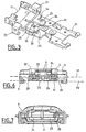
- the brake frame 11 also has a retaining part under the shape of two legs 23, 24 directed parallel to the plane of the base of the attachment 4, that is to say at the plane of the slide 2.
- These tabs 23, 24 are of shape generally rectangular planar and have laterally, each a notch 26, respectively 27.
- the tab 23 which has its smooth side oriented towards the outside comprises furthermore, a protuberance 28 positioned on this side opposite the notch 26, and deploying substantially downward from the plane of said tab 23.
- a first plane P1 defined by the inner lower surface of the base 4 of the binding is vertically offset with respect to a second plane P2 corresponding to the sliding of the slide 2, so as to form a free volume 29 of general shape substantially parallelepiped.
- a flat reinforcement 31, generally metallic is mounted parallel to the base 4, for example by riveting, while delimiting using perpendicular fixings, a housing 32 between the reinforcement armature 31 and the first plane P1 of the base 4.
- the reinforcing reinforcement 31 further comprises two fixed projections 33, 34 which are oriented perpendicular to the plane of the reinforcement 31 and therefore relative to the plane of the base 4.
- the two projections 33, 34 are under the shape of two small rectangular parallelepipeds, which are directed towards the base 4.
- the two projections 33, 34 have a sufficiently large dimension in the direction longitudinal to withstand the brake pulling forces 9 in the direction longitudinal, for example when pairing the two skis to transport them.
- the shape of the projections 33, 34 corresponds to the shape of the notches 26, 27 legs 23, 24.
- the two projections 33, 34 extend into the base 4 and fit into the structure of the base 4.
- the housing 32 has an opening at the front which allows passage of the two legs 23, 24 with very little play.
- the base 4 further comprises a lateral notch 36 under the form of a cutout made in the slide of the base 4.
- the mounting of the brake 9 on the base 4 of the binding 1 will be done all first by pushing in a longitudinal engagement movement (arrow L on Figure 4) followed by displacement in a transverse movement (arrow T on the figure 4).
- This longitudinal movement L is carried out with the brake 9 offset laterally, so that the ends of the legs 23, 24 do not come up against the projections 33, 34.
- the longitudinal movement L allows the brake frame 11 to go through the lateral notch 36, then at the end of the race, the legs 23, respectively 24, will be positioned opposite the projections 33, respectively 34.
- the transverse movement T will cause the notches 26, respectively 27, of the legs 23, respectively 24, will abut against the corresponding projections 33, respectively 34.
- the lateral locking of the brake 9 is then obtained by the slide 2, when the brake 9 and base 4 assembly is finally engaged on the slide 2.
- the disassembly of the brake 9 on the base 4 of the binding will first do this by separating the brake 9 and base 4 assembly from the slide 2, then by moving the brake 9 in a transverse movement, and finally by pulling the brake 9 according to a longitudinal exit movement.
- the ski binding with its removable brake is not limited to the mode described and illustrated.
- the number, arrangement and form tabs 23, 24, notches 26, 27, and projections 33, 34 may vary.
- the protrusions 33, 34 could also come directly from the base 4.
Landscapes
- Braking Arrangements (AREA)
- Scissors And Nippers (AREA)
- Handcart (AREA)
- Footwear And Its Accessory, Manufacturing Method And Apparatuses (AREA)
- Fittings On The Vehicle Exterior For Carrying Loads, And Devices For Holding Or Mounting Articles (AREA)
- Connection Of Plates (AREA)
Applications Claiming Priority (2)
| Application Number | Priority Date | Filing Date | Title |
|---|---|---|---|
| FR0001294A FR2804338B1 (fr) | 2000-02-02 | 2000-02-02 | Fixation de ski a frein demontable |
| FR0001294 | 2000-02-02 |
Publications (2)
| Publication Number | Publication Date |
|---|---|
| EP1121960A1 true EP1121960A1 (de) | 2001-08-08 |
| EP1121960B1 EP1121960B1 (de) | 2006-06-07 |
Family
ID=8846568
Family Applications (1)
| Application Number | Title | Priority Date | Filing Date |
|---|---|---|---|
| EP01420017A Expired - Lifetime EP1121960B1 (de) | 2000-02-02 | 2001-01-24 | Skibindung mit abnehmbarer Bremse |
Country Status (5)
| Country | Link |
|---|---|
| US (1) | US6443477B2 (de) |
| EP (1) | EP1121960B1 (de) |
| AT (1) | ATE328651T1 (de) |
| DE (1) | DE60120242T2 (de) |
| FR (1) | FR2804338B1 (de) |
Cited By (1)
| Publication number | Priority date | Publication date | Assignee | Title |
|---|---|---|---|---|
| US7393000B2 (en) | 2005-08-08 | 2008-07-01 | Atomic Austria Gmbh | Coupling device |
Families Citing this family (2)
| Publication number | Priority date | Publication date | Assignee | Title |
|---|---|---|---|---|
| KR100612382B1 (ko) * | 2003-11-29 | 2006-08-16 | 삼성에스디아이 주식회사 | 플라즈마 디스플레이 패널 및 그 제조 방법 |
| DE102019108350A1 (de) * | 2019-03-29 | 2020-10-01 | Marker Deutschland Gmbh | Bremsvorrichtung |
Citations (8)
| Publication number | Priority date | Publication date | Assignee | Title |
|---|---|---|---|---|
| FR2265420A1 (de) | 1974-04-02 | 1975-10-24 | Salomon & Fils F | |
| FR2383681A1 (fr) | 1977-03-15 | 1978-10-13 | Beyl Jean Joseph Alfred | Fixation de ski, associee a un accessoire, tel que frein ou plaque de glissement |
| FR2447732A1 (fr) | 1979-02-05 | 1980-08-29 | Tmc Corp | Piece de jonction pour l'accouplement amovible d'une plaque d'appui de semelle et d'un element de fixation de ski |
| US4230337A (en) * | 1977-12-19 | 1980-10-28 | Verrinigte Baubeschlagfabriken Gretsch Co. Gmbh | Ski bindings and ski brakes associated therewith |
| FR2668941A1 (fr) | 1990-11-09 | 1992-05-15 | Salomon Sa | Fixation de securite de ski alpin. |
| FR2692804A1 (fr) | 1992-06-30 | 1993-12-31 | Salomon Sa | Fixation de ski alpin. |
| FR2741275A1 (fr) | 1995-11-21 | 1997-05-23 | Look Fixations Sa | Fixation de ski equipee d'un frein demontable |
| FR2779971A1 (fr) | 1998-06-19 | 1999-12-24 | Look Fixations Sa | Element de fixation de ski alpin equipe d'un frein demontable |
Family Cites Families (8)
| Publication number | Priority date | Publication date | Assignee | Title |
|---|---|---|---|---|
| US3930659A (en) | 1973-06-29 | 1976-01-06 | S.A. Francois Salomon & Fils | Ski brake |
| AT341925B (de) * | 1975-10-24 | 1978-03-10 | Smolka & Co Wiener Metall | Skibremse |
| DE2632874C2 (de) * | 1976-07-21 | 1986-08-21 | S.A. Etablissements François Salomon et Fils, Annecy, Haute-Savoie | Skibremse |
| US4083576A (en) * | 1977-02-04 | 1978-04-11 | Von Besser Kurt | Adjustable ski brake |
| DE2811734A1 (de) * | 1978-03-17 | 1979-09-20 | Wiedermann Riedel Gmbh | Halteplatte zur lagerung von skistoppern |
| FR2453606A1 (fr) * | 1978-07-04 | 1980-11-07 | Salomon & Fils F | Ensemble de fixation de ski a pivot equipe d'un systeme de freinage |
| FR2631555B1 (fr) * | 1988-05-18 | 1990-08-17 | Salomon Sa | Frein de ski |
| US5324062A (en) * | 1989-12-15 | 1994-06-28 | Salomon S.A. | Safety binding for alpine skis |
-
2000
- 2000-02-02 FR FR0001294A patent/FR2804338B1/fr not_active Expired - Fee Related
-
2001
- 2001-01-24 DE DE60120242T patent/DE60120242T2/de not_active Expired - Lifetime
- 2001-01-24 AT AT01420017T patent/ATE328651T1/de not_active IP Right Cessation
- 2001-01-24 US US09/768,963 patent/US6443477B2/en not_active Expired - Fee Related
- 2001-01-24 EP EP01420017A patent/EP1121960B1/de not_active Expired - Lifetime
Patent Citations (8)
| Publication number | Priority date | Publication date | Assignee | Title |
|---|---|---|---|---|
| FR2265420A1 (de) | 1974-04-02 | 1975-10-24 | Salomon & Fils F | |
| FR2383681A1 (fr) | 1977-03-15 | 1978-10-13 | Beyl Jean Joseph Alfred | Fixation de ski, associee a un accessoire, tel que frein ou plaque de glissement |
| US4230337A (en) * | 1977-12-19 | 1980-10-28 | Verrinigte Baubeschlagfabriken Gretsch Co. Gmbh | Ski bindings and ski brakes associated therewith |
| FR2447732A1 (fr) | 1979-02-05 | 1980-08-29 | Tmc Corp | Piece de jonction pour l'accouplement amovible d'une plaque d'appui de semelle et d'un element de fixation de ski |
| FR2668941A1 (fr) | 1990-11-09 | 1992-05-15 | Salomon Sa | Fixation de securite de ski alpin. |
| FR2692804A1 (fr) | 1992-06-30 | 1993-12-31 | Salomon Sa | Fixation de ski alpin. |
| FR2741275A1 (fr) | 1995-11-21 | 1997-05-23 | Look Fixations Sa | Fixation de ski equipee d'un frein demontable |
| FR2779971A1 (fr) | 1998-06-19 | 1999-12-24 | Look Fixations Sa | Element de fixation de ski alpin equipe d'un frein demontable |
Cited By (1)
| Publication number | Priority date | Publication date | Assignee | Title |
|---|---|---|---|---|
| US7393000B2 (en) | 2005-08-08 | 2008-07-01 | Atomic Austria Gmbh | Coupling device |
Also Published As
| Publication number | Publication date |
|---|---|
| DE60120242T2 (de) | 2006-10-12 |
| US20010010421A1 (en) | 2001-08-02 |
| FR2804338B1 (fr) | 2002-03-08 |
| US6443477B2 (en) | 2002-09-03 |
| ATE328651T1 (de) | 2006-06-15 |
| EP1121960B1 (de) | 2006-06-07 |
| FR2804338A1 (fr) | 2001-08-03 |
| DE60120242D1 (de) | 2006-07-20 |
Similar Documents
| Publication | Publication Date | Title |
|---|---|---|
| EP3144199B1 (de) | Vorrichtung zur erhöhung von komfort, insbesondere für ein schienenfahrzeug, umfassend einen herausnehmbaren tisch | |
| FR2853865A1 (fr) | Glissiere pour siege de vehicule | |
| EP0296898A1 (de) | Schuhbefestigungsvorrichtung an einem Fahrradpedal | |
| EP3050603B1 (de) | Perfektionierung für griff mit schlaufe eines ski- oder gehstocks | |
| EP0134595A1 (de) | Skischuh | |
| FR2700309A1 (fr) | Dispositif de liaison pour le raccordement et l'articulation d'un balai d'essuie-glace à l'extrémité d'un balai d'essuie-glace. | |
| FR2534619A1 (fr) | Charniere | |
| FR2847530A1 (fr) | Glissiere pour siege de vehicule automobile et siege de vehicule comprenant une telle glissiere | |
| EP1121960B1 (de) | Skibindung mit abnehmbarer Bremse | |
| EP0965369B1 (de) | Bindungselement fur einen alpinen Ski mit abnehmbarer Bremse | |
| EP1022213A1 (de) | Automatisches Pedal für Fahrrad | |
| EP1325768A1 (de) | Langlaufskibindung | |
| FR2901193A1 (fr) | Glissiere de siege de vehicule automobile a verrous imbriques | |
| FR2867499A1 (fr) | Verrou de couverture de piscine | |
| FR2810929A1 (fr) | Dispositif d'assise pour vehicule | |
| CH695656A5 (fr) | Maillon réglable en longueur notamment pour bracelet à maillons. | |
| FR3010116A1 (fr) | Gache destinee a cooperer avec la serrure d'un ouvrant de vehicule automobile | |
| FR2952327A1 (fr) | Glissiere pour siege de vehicule automobile | |
| WO2002085473A1 (fr) | Dispositif de montage, demontage rapides d'une fixation de ski sur un ski | |
| EP0517619B1 (de) | Elektrische Anschlussleiste | |
| FR2873674A1 (fr) | Etrier de securite | |
| FR2590222A1 (fr) | Dispositif de fixation et de securite pour pedales de bicyclettes et de vehicules similaires | |
| FR2706409A1 (fr) | Dispositif d'accrochage réversible d'un siège sur un plancher de véhicule automobile. | |
| FR2536128A1 (fr) | Agrafe elastique pour fixer un panneau sur un support | |
| EP2355252B1 (de) | Anschlagbacke |
Legal Events
| Date | Code | Title | Description |
|---|---|---|---|
| PUAI | Public reference made under article 153(3) epc to a published international application that has entered the european phase |
Free format text: ORIGINAL CODE: 0009012 |
|
| AK | Designated contracting states |
Kind code of ref document: A1 Designated state(s): AT CH DE FR LI |
|
| AX | Request for extension of the european patent |
Free format text: AL;LT;LV;MK;RO;SI |
|
| 17P | Request for examination filed |
Effective date: 20011106 |
|
| AKX | Designation fees paid |
Free format text: AT CH DE FR LI |
|
| GRAP | Despatch of communication of intention to grant a patent |
Free format text: ORIGINAL CODE: EPIDOSNIGR1 |
|
| GRAS | Grant fee paid |
Free format text: ORIGINAL CODE: EPIDOSNIGR3 |
|
| GRAA | (expected) grant |
Free format text: ORIGINAL CODE: 0009210 |
|
| RAP1 | Party data changed (applicant data changed or rights of an application transferred) |
Owner name: LOOK FIXATIONS |
|
| AK | Designated contracting states |
Kind code of ref document: B1 Designated state(s): AT CH DE FR LI |
|
| REG | Reference to a national code |
Ref country code: CH Ref legal event code: EP |
|
| REF | Corresponds to: |
Ref document number: 60120242 Country of ref document: DE Date of ref document: 20060720 Kind code of ref document: P |
|
| PLBE | No opposition filed within time limit |
Free format text: ORIGINAL CODE: 0009261 |
|
| STAA | Information on the status of an ep patent application or granted ep patent |
Free format text: STATUS: NO OPPOSITION FILED WITHIN TIME LIMIT |
|
| 26N | No opposition filed |
Effective date: 20070308 |
|
| REG | Reference to a national code |
Ref country code: FR Ref legal event code: ST Effective date: 20070930 |
|
| PG25 | Lapsed in a contracting state [announced via postgrant information from national office to epo] |
Ref country code: FR Free format text: LAPSE BECAUSE OF NON-PAYMENT OF DUE FEES Effective date: 20070131 |
|
| PGFP | Annual fee paid to national office [announced via postgrant information from national office to epo] |
Ref country code: CH Payment date: 20080114 Year of fee payment: 8 |
|
| PGFP | Annual fee paid to national office [announced via postgrant information from national office to epo] |
Ref country code: AT Payment date: 20081219 Year of fee payment: 9 |
|
| REG | Reference to a national code |
Ref country code: CH Ref legal event code: PL |
|
| PG25 | Lapsed in a contracting state [announced via postgrant information from national office to epo] |
Ref country code: LI Free format text: LAPSE BECAUSE OF NON-PAYMENT OF DUE FEES Effective date: 20090131 Ref country code: CH Free format text: LAPSE BECAUSE OF NON-PAYMENT OF DUE FEES Effective date: 20090131 |
|
| PGFP | Annual fee paid to national office [announced via postgrant information from national office to epo] |
Ref country code: DE Payment date: 20100113 Year of fee payment: 10 |
|
| PG25 | Lapsed in a contracting state [announced via postgrant information from national office to epo] |
Ref country code: AT Free format text: LAPSE BECAUSE OF NON-PAYMENT OF DUE FEES Effective date: 20100124 |
|
| REG | Reference to a national code |
Ref country code: DE Ref legal event code: R119 Ref document number: 60120242 Country of ref document: DE Effective date: 20110802 |
|
| PG25 | Lapsed in a contracting state [announced via postgrant information from national office to epo] |
Ref country code: DE Free format text: LAPSE BECAUSE OF NON-PAYMENT OF DUE FEES Effective date: 20110802 |