EP1121994A1 - Verfahren zum wickeln von band - Google Patents
Verfahren zum wickeln von band Download PDFInfo
- Publication number
- EP1121994A1 EP1121994A1 EP99944792A EP99944792A EP1121994A1 EP 1121994 A1 EP1121994 A1 EP 1121994A1 EP 99944792 A EP99944792 A EP 99944792A EP 99944792 A EP99944792 A EP 99944792A EP 1121994 A1 EP1121994 A1 EP 1121994A1
- Authority
- EP
- European Patent Office
- Prior art keywords
- strip
- coiling
- pinch rolls
- mandrel
- speed
- Prior art date
- Legal status (The legal status is an assumption and is not a legal conclusion. Google has not performed a legal analysis and makes no representation as to the accuracy of the status listed.)
- Granted
Links
Images


Classifications
-
- B—PERFORMING OPERATIONS; TRANSPORTING
- B21—MECHANICAL METAL-WORKING WITHOUT ESSENTIALLY REMOVING MATERIAL; PUNCHING METAL
- B21C—MANUFACTURE OF METAL SHEETS, WIRE, RODS, TUBES, PROFILES OR LIKE SEMI-MANUFACTURED PRODUCTS OTHERWISE THAN BY ROLLING; AUXILIARY OPERATIONS USED IN CONNECTION WITH METAL-WORKING WITHOUT ESSENTIALLY REMOVING MATERIAL
- B21C47/00—Winding-up, coiling or winding-off metal wire, metal band or other flexible metal material characterised by features relevant to metal processing only
- B21C47/02—Winding-up or coiling
-
- B—PERFORMING OPERATIONS; TRANSPORTING
- B21—MECHANICAL METAL-WORKING WITHOUT ESSENTIALLY REMOVING MATERIAL; PUNCHING METAL
- B21C—MANUFACTURE OF METAL SHEETS, WIRE, RODS, TUBES, PROFILES OR LIKE SEMI-MANUFACTURED PRODUCTS OTHERWISE THAN BY ROLLING; AUXILIARY OPERATIONS USED IN CONNECTION WITH METAL-WORKING WITHOUT ESSENTIALLY REMOVING MATERIAL
- B21C47/00—Winding-up, coiling or winding-off metal wire, metal band or other flexible metal material characterised by features relevant to metal processing only
- B21C47/003—Regulation of tension or speed; Braking
Definitions
- the present invention relates to a strip coiling method in which a strip sent from a hot rolling mill is cut to a predetermined length by a strip shear and the cut strip is coiled by a mandrel of a coiler via coiling pinch rolls disposed on the delivery side of a strip shear.
- Figure 16 shows a general arrangement of a general continuous hot rolling line.
- changeover of coilers has been effected as described below when a strip cut to a predetermined length by a strip shear is coiled by the preceding material coiler and the following material coiler alternately.
- a strip d sent from a finishing mill c is cut to a predetermined length by a strip shear e disposed on the downstream side of the finishing mill c to divide the strip d into the preceding strip d 1 and the following strip d 2 .
- the preceding strip d 1 and the following strip d 2 are coiled by the preceding material coiler a and the following material coiler b , respectively.
- a lower pinch roll g of a coiling pinch roll f disposed on the delivery side of the strip shear e is moved to the upstream side.
- the offset angle of the coiling pinch roll f is changed to change the transfer direction of the strip from the preceding material coiler a to the following material coiler b .
- the following strip d 2 is introduced to the following material coiler b to coil the following strip d 2 by using the following material coiler b .
- a triangular gate j prevents the following strip d 2 from going to the side of the preceding material coiler a .
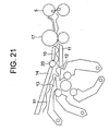
- Figure 20 schematically shows an example of a continuous hot rolling line in which a Carrousel reel type coiler is used.
- the Carrousel reel type coiler has a first and second mandrels 1 and 2.
- the first and second mandrels 1 and 2 are revolvably disposed at an interval in the circumferential direction on a revolution path 3 so that when one mandrel is located at a coiling start position, the other mandrel is located at a coiling finish position.
- the preceding strip S 1 sent from a finishing mill 4 is coiled by a predetermined amount by the first mandrel 1, and then the first mandrel 1 is revolved to the coiling finish position while coiling the preceding strip S 1 .
- the tail end of the preceding strip S 1 is cut by a strip shear 5, and the leading end of the following strip S 2 is coiled by the second mandrel 2 located at the coiling start position.
- the coil of the coiled preceding strip S 1 is delivered from the mandrel 1, and the mandrel 1 waits until the leading end of a strip following the following strip S 2 is coiled around the mandrel 1.
- upstream sheet-running guides 6 to 13 for guiding the leading end of the strip S toward the upstream mandrel are disposed.
- downstream pass line P 2 that branches off the upstream pass line P 1 and is directed toward the mandrel at the coiling finish position (the second mandrel 2 in the figure)
- downstream sheet-running guides 13 to 15 and a guide roller 20 for guiding the strip S coiled by the mandrel at the coiling finish position are disposed.
- the sheet-running guide 13 is disposed at a position where the downstream pass line P 2 branches off the upstream pass line P 1 so as to be used as both an upper guide for the upstream pass line P 1 and a lower guide for the downstream pass line P 2 .
- reference numeral 16 denotes pinch rolls disposed on the pass line P 1 between the finishing mill 4 and the strip shear 5
- 17 denotes coiling pinch rolls disposed on the pass line P 1 on the delivery side of the strip shear
- 18 denotes upstream wrapper rolls disposed movably so as to come close to and go apart from the outer peripheral surface of the mandrel at the coiling start position
- 19 denotes downstream wrapper rolls disposed movably so as to come close to and go apart from the outer peripheral surface of the mandrel at the coiling finish position.
- the upstream and downstream wrapper rolls 18 and 19 and the upper guide 14 of the downstream sheet-running guide is movable so as to be separated from the revolution path 3 to allow the revolution of the first and second mandrels 1 and 2 when the mandrels 1 and 2 revolves on the revolution path 3.
- the present invention has been achieved to solve the above problems, and accordingly an object thereof is to provide a strip coiling method in which after the tail end of a strip coiled by a mandrel is cut by a strip shear, the strip can be prevented from being oversupplied on the delivery side of coiling pinch rolls disposed on the delivery side of the strip shear, and the leading end of the following strip can be prevented from being oversupplied on the entrance side of the coiling pinch rolls.
- the present invention provides a strip coiling method in which a strip sent from a rolling mill is cut to a predetermined length by a strip shear, and the cut strip is coiled by a mandrel of a coiler via coiling pinch rolls disposed on the delivery side of the strip shear, characterized in that after the tail end of the strip coiled by the mandrel via the coiling pinch rolls is cut by the strip shear, the circumferential speed of the coiling pinch rolls is higher than the transfer speed of the following material immediately after the cutting operation and lower than the coiling speed of the strip coiled by the mandrel.
- a force pulling the strip between the strip shear and the coiling pinch rolls toward the downstream side is applied to the strip having been cut, and a force pulling the strip between the coiling pinch rolls and the mandrel toward the downstream side is also applied to the strip. Therefore, the preceding strip can be prevented from being oversupplied on the delivery side of the coiling pinch rolls. Moreover, since the circumferential speed of the coiling pinch rolls is higher than the transfer speed of the following material immediately after the cutting operation, the leading end of the following material can be prevented from being oversupplied on the entrance side of the coiling pinch rolls.
- the aforementioned mandrel is a mandrel of a Carrousel reel type coiler, and the relationship between a preset coiling speed V m of the mandrel after the tail end of the strip coiled by the mandrel via the coiling pinch rolls, the target speed V p of the coiling pinch rolls at the time of the cutting operation, and the sheet speed V s of the following material immediately after the cutting operation is set so that V m >V p >V s .
- the preceding strip can be prevented frombeing caught by the tip end of a sheet-running guide located at a position where a pass line directed to the mandrel at the coiling start position branches off a pass line directed to the mandrel at the coiling finish position.
- the relationship between the target speed V p1 of the second coiling pinch rolls after the tail end of the strip coiled by a downstream mandrel via second coiling pinch rolls disposed on the entrance side of the downstream mandrel is cut by the strip shear, the target speed V p2 of the first coiling pinch rolls, the target sheet speed V s of the following material immediately after the cutting operation, and the preset coiling speed V m of the downstream mandrel is set so that V m > V p1 > V p2 > V s .
- the strip is pressed by the upper pinch roll of the first coiling pinch rolls in a state in which the speed of the lower pinch roll is made lower than the target sheet speed V s of the following material until the actual torque value of the lower pinch roll becomes the preset value, and the pressing force at this time is made the preset pressing force of the offset upper pinch roll applied to the strip, by which the tail end of the strip coiled by the downstream mandrel can be held properly by the first coiling pinch rolls.
- P 2F( ⁇ u/ ⁇ x) + 4(M B / ⁇ x) ⁇ (1 a /R L ) + (1 b /R U ) ⁇ .
- the strip coiling control carried out by the mandrel is changed over from torque control to rotational speed control, and thereafter a pressing roll is pressed on the strip to be coiled into a coil shape to stop the rotation of the mandrel.
- the decrease in speed of coil caused by the contact of the pressing roll can be prevented, so that the occurrence of defective coiling such as loosened coil outer and telescoping can be avoided, and the rotation of coil can be stopped in a short time because the pressing roll has a braking force when the rotation of coil is stopped after the strip coiling operation is finished.
- the torque control of strip is carried out by the mandrel to increase the tension of strip, and thereafter the pressing roll is pressed on the strip to be coiled into a coil shape to stop the rotation of the mandrel.
- the decrease in speed of coil caused by the contact of the pressing roll can be prevented, so that the occurrence of defective coiling such as loosened coil outer and telescoping can be avoided, and the rotation of coil can be stopped in a short time because the pressing roll has a braking force when the rotation of coil is stopped after the strip coiling operation is finished.
- a deceleration-side torque limit of a driving unit for the coiling pinch rolls is set so that the circumferential speed of the coiling pinch rolls is higher than the transfer speed of the following material when the leading end of the following material is bitten by the coiling pinch rolls disposed on the delivery side of the strip shear after the strip is cut by the strip shear.
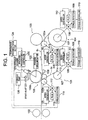
- Figure 1 schematically shows a portion of a continuous hot rolling line on the downstream side of a strip shear.
- a strip sent from a finishing mill (not shown) is cut to a predetermined length by using a strip shear 102, and the preceding strip S 1 is coiled by a mandrel 107 of a downstream coiler 104 via downstream coiling pinch rolls (second coiling pinch rolls) 103, whereas the following strip S 2 is coiled by a mandrel 107 of an upstream coiler 101 via upstream coiling pinch rolls (first coiling pinch rolls) 105 disposed on the delivery side of the strip shear 102 is explained by way of example.
- Both of the downstream coiler 104 and the upstream coiler 101 are provided with a torque detector 109 for detecting a torque of a motor 108 for driving the mandrel 107, a torque controller 110 for keeping the tension of a strip constant by feedback controlling the motor 108 so that the detected torque value obtained by the torque detector 109 coincides with the target torque value, a pilot generator (PLG) 111 for detecting the rotational state of the motor 108, and a speed controller 112 for feedback controlling the motor 108 so that the speed detection value obtained by the pilot generator 111 coincides with the target speed, as means for pulling the strip coiled around the mandrel 107 with a predetermined coiling tension.
- PSG pilot generator
- the downstream coiling pinch rolls 103 are provided with a torque detector 114 for detecting a torque of a motor 113 for a lower pinch roll 103a, a pilot generator (PLG) 115 for detecting the rotational state of the motor 113, and a speed controller 116 for feedback controlling the motor 113 so that the speed detection value obtained by the pilot generator 115 coincides with the target speed V p1 .
- a torque detector 114 for detecting a torque of a motor 113 for a lower pinch roll 103a
- PLG pilot generator
- speed controller 116 for feedback controlling the motor 113 so that the speed detection value obtained by the pilot generator 115 coincides with the target speed V p1 .
- the upstream coiling pinch rolls 105 are also provided with a torque detector 118 for detecting a torque of a motor 117 for a lower pinch roll 105a, a pilot generator (PLG) 119 for detecting the rotational state of the motor 117, and a speed controller 120 for feedback controlling the motor 117 so that the speed detection value obtained by the pilot generator 119 coincides with the target value V p2 .
- the lower pinch roll 105a can be moved to the upstream side along a pass line when the offset angle is changed to effect changeover from the downstream coiler 104 to the upstream coiler 101, and the upper pinch roll 105b can press a strip via a hydraulic cylinder 121 to push down the strip.
- the upper pinch roll 105b is provided with a pressing force detector 122 for detecting a pressing force applied to the upper pinch roll 105b.
- the pressing force applied to the upper pinch roll 105b via the hydraulic cylinder 121 is determined by feedback controlling a servo valve 127 for switching oil supplied from a hydraulic pump 126 to the hydraulic cylinder 121 by a pinch roll pressing force controller 125 so that the detected pressing force obtained by the pressing force detector 122 coincides with the preset pressing force set beforehand by a compensation pressing force setter 124.
- the pressing force control for the pinch roll may be carried out by using air.
- the coiling speed V m of the preceding strip S 1 set by the speed controller 112 for the coiler 104 , the target speed V p2 for the speed controller 120 on the side of the upstream coiling pinch rolls 105, the target speed V p1 for the speed controller 116 on the side of the downstream coiling pinch rolls 103, and the transfer speed V s of the following strip S 2 immediately after the cutting operation are set by a host computer (not shown) so that V m > V p1 > V p2 > V s .
- a cutting finish signal for telling that the cutting operation has finished is sent from the strip shear 102 or the host computer to the speed controller 112 for the downstream coiler 104, the speed controller 116 for the downstream coiling pinch rolls 103, and the speed controller 120 for the upstream coiling pinch rolls 105.
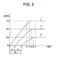
- the mandrel 107 of the downstream coiler 104 is changed over from tension control by the torque controller 110 to speed control by the speed controller 112 at timing of the time t 0 .
- the speed controller 112 starts acceleration of coiling speed of strip at the timing of the time t 0 , and also, as indicated by the curve I in Figure 2, speed control is started so that the final speed V m after the completion of acceleration with the acceleration rate of X is expressed by the following equation (1).
- V m V s ⁇ A
- V s is the transfer speed of strip just before the cutting operation
- A is a lead coefficient (a coefficient for determining the final speed).
- the speed of the downstream coiling pinch rolls 103 is kept at the strip speed V s just before the cutting operation by the speed controller 116 for the downstream coiling pinch rolls 103.
- the speed controller 116 starts the increase in speed of the downstream coiling pinch rolls 103, and also, as indicated by the curve II in Figure 2, speed control is started so that the final speed V p1 after the completion of acceleration with the acceleration rate of Y is expressed by the following equation (2).
- the time counting of the delay time T1 is performed by a timer provided on the speed controller 116 or the host computer.
- V p1 V s ⁇ B where B is a lead coefficient, and the relationship between the lead coefficients A and B is A > B.
- the speed of the upstream coiling pinch rolls 105 is kept at the strip speed V s just before the cutting operation by the speed controller 120 for the upstream coiling pinch rolls 105.
- the speed controller 120 starts the increase in speed of the upstream coiling pinch rolls 105, and also, as indicated by the curve III in Figure 2, speed control is started so that the final speed V p2 after the completion of acceleration with the acceleration rate of Z is expressed by the following equation (3).
- the time counting of the delay time T2 is performed by a timer provided on the speed controller 120 or the host computer (not shown), and the relationship between the delay times T1 and T2 is T1 ⁇ T2.
- V p2 V s ⁇ C where C is a lead coefficient, and the relationship between the lead coefficients B and C is B > C.
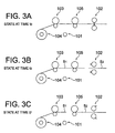
- time t 3 is reached, as shown in Figure 3(B), the tail end of the preceding strip S 1 and the leading end of the following strip S 2 are located between the upstream coiling pinch rolls 105 and the strip shear 102, and the tail end of the preceding strip S 1 is sufficiently separated from the leading end of the following strip S 2 .
- time t 4 is reached, the coiling speed of the mandrel 107 of the downstream coiler 104 becomes the final speed V m .
- time t 5 is reached, the speed of the downstream coiling pinch rolls 103 becomes the final speed V p1 .
- time t 6 the speed of the upstream coiling pinch rolls 105 becomes the final speed V p2 .
- a speed ratio x of the final speed V m to the final speed V p1 and a speed ratio y of the final speed V p1 to the final speed V p2 become as expressed by the following equations.
- the lead coefficients A, B and C are preferably higher from the viewpoint of the coiling property of strip on the downstream coiler 104.
- the lead coefficients are determined empirically with an emphasis on the coiling property according to the sheet thickness.
- the above-described speed ratio x be ensured, and for the speed ratio in the acceleration process of the downstream coiling pinch rolls 103 and the upstream coiling pinch rolls 105, the above-described speed ratio y be ensured.
- the delay time T1 is expressed by the following equation.
- the distance between the upstream coiling pinch rolls 105 and the strip shear 102 is 10 [m]
- the speed V s of strip just before the cutting operation is 900 [mpm]
- the tail end of the preceding strip S 1 is prevented from being oversupplied on the delivery side of the coiling pinch rolls 105, that is, between the coiler 104 and the downstream coiling pinch rolls 103 and between the downstream coiling pinch rolls 103 and the upstream coiling pinch rolls 105.
- damage to the strip caused by the tail end of the preceding strip S 1 being caught by a triangular gate 26 can be prevented.
- the feed speed of the coiling pinch rolls 105 is set so as to be higher than the transfer speed of the following strip S 2 as indicated by V p2 >V s , the leading end of the following strip S 2 can be prevented from being oversupplied on the entrance side of the coiling pinch rolls 105.
- the pressing force detector 122 for the upstream coiling pinch rolls 105 is provided on the side of the upper pinch roll 105b as shown in Figure 1, when the offset angle of the upstream coiling pinch rolls 105 is changed in the state in which the preceding strip S 1 is coiled around the mandrel 107 of the downstream coiler 104, it is necessary that the preceding strip S 1 should be pressed down from the pass line according to the offset amount of the lower pinch roll 105a, and the strip S 1 should be held between the upper and lower pinch rolls 105b and 105a.
- the upper pinch roll 105b of the upstream coiling pinch rolls 105 presses the preceding strip S 1 via the hydraulic cylinder 121, and the pressing force at this time is set by the compensation pressing force setter 124.
- the compensation pressing force setter 124 sets a compensation pressing force for surely holding the preceding strip S 1 between the upper pinch roll 105b and the lower pinch roll 105a of the upstream coiling pinch rolls 105.
- the speed controller 120 is controlled so that the speed reference of the lower pinch roll 105a is slightly lower than the sheet speed V s of the preceding strip S 1 .
- the servo valve 127 is feedback controlled via the pinch roll pressing force controller 125 until the torque value T detected by the torque detector 118 becomes the preset value T 0 , and the strip S 1 is pressed continuously.
- the speed reference of the lower pinch roll 105a is made slightly lower than the sheet speed V s of the preceding strip S 1 , unless the preceding strip S 1 is pressed with a desirable pressing force, a load is scarcely applied to the lower pinch roll 105a, so that the torque of the lower pinch roll 105a does not increase. If the preceding strip S 1 is pressed with the desirable pressing force, the preceding strip S 1 slips with respect to the lower pinch roll 105a, so that the load (torque) increases. By utilizing this, the compensation pressing force (in this case, the force that holds the preceding strip S 1 between the upper pinch roll 105b and the lower pinch roll 105a) P s (N) is estimated.
- the compensation pressing force in this case, the force that holds the preceding strip S 1 between the upper pinch roll 105b and the lower pinch roll 105a
- the compensation pressing force P s can be determined by measuring the actual torque T of the lower pinch roll.
- the compensation pressing force P s1 that can hold the strip S 1 between the upstream coiling pinch rolls 105 to a degree such that the tail end of the preceding strip S 1 does not wrinkle is determined beforehand, and when before the cutting operation is performed, the speed of the lower pinch roll 105a is set so as to be lower than the sheet speed V s of the strip S 1 by the predetermined speed ⁇ v, the torque value T 0 of the lower pinch roll 105a at the time when the compensation pressing force is P s1 is preset in the compensation pressing force setter 124.
- the compensation pressing force setter 124 sends a signal to the speed controller 120 so that the speed of the lower pinch roll 105a is lower than the sheet speed V s by ⁇ v, and then sends a signal to the pinch roll pressing force controller 125 so that the strip S 1 is pressed by the upper pinch roll 105b while measuring the actual torque T of the lower pinch roll 105a by using the torque detector 118.
- the actual torque T is made a value not lower than T 0 . Therefore, the strip S 1 can be held surely between the upstream coiling pinch rolls 105. In this state, the tail end of the preceding strip S 1 is cut by the strip shear 102.
- the compensation pressing force setter 124 When the compensation pressing force setter 124 is used in this manner, since the pressing force is set considering the actual force applied to the preceding strip S 1 , the preceding strip S 1 can be held surely between the upper pinch roll 105b and the lower pinch roll 105a of the upstream coiling pinch rolls 105, whereby the occurrence of slip can be prevented. As a result, the tail end of the preceding strip S 1 can be prevented satisfactorily from being oversupplied between the downstream coiler 1 and the upstream coiler 6.
- the control for ensuring the speed relationship of V m > V p1 > V p2 > V s by using the host computer and the pressing of the preceding strip S 1 by using the compensation pressing force setter 24 are carried out until the tail end of the preceding strip S 1 is coiled around the mandrel 107 of the downstream coiler 104.
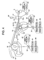
- Figure 4 schematically shows a portion of a continuous hot rolling line on the downstream side of a strip shear.
- a strip sent from a finishing mill (not shown) is cut to a predetermined length by using a strip shear 5
- the preceding strip S 1 is coiled by a mandrel at a coiling finish position (a second mandrel 2 in the figure) via coiling pinch rolls 17 disposed on the delivery side of the strip shear 5
- the following strip S 2 is coiled by a mandrel at a coiling start position (a first mandrel 1 in the drawing) via coiling pinch rolls 17 is explained by way of example.
- the second mandrel 2 located at the coiling finish position is provided with a torque detector 34 for detecting a torque of a motor 32 for driving the mandrel 2, a torque controller 36 for keeping the tension of a strip constant by feedback controlling the motor 32 so that the detected torque value obtained by the torque detector 34 coincides with the target torque value, a pilot generator (PLG) 38 for detecting the rotational state of the motor 32, and a speed controller 40 for feedback controlling the motor 32 so that the speed detection value obtained by the pilot generator 38 coincides with the target speed, as means for pulling a strip coiled around the mandrel 2 with a predetermined coiling tension.
- PSG pilot generator
- the first mandrel 1 located at the coiling start position is also provided with a torque detector 33 for detecting a torque of a motor 31 for driving the mandrel 1, a torque controller 35 for keeping the tension of the strip constant by feedback controlling the motor 31 so that the detected torque value obtained by the torque detector 33 coincides with the target torque value, a pilot generator (PLG) 37 for detecting the rotational state of the motor 31, and a speed controller 39 for feedback controlling the motor 31 so that the speed detection value obtained by the pilot generator 37 coincides with the target speed, as means for pulling a strip coiled around the mandrel 1 with a predetermined coiling tension.
- PSG pilot generator
- the coiling pinch rolls 17 have a pilot generator (PLG) 42 for detecting the rotational state of a motor 41 for a lower pinch roll 17a, and a speed controller 43 for feedback controlling the motor 41 so that the speed detection value obtained by the pilot generator 42 coincides with the target speed V p .
- PLG pilot generator
- An upper pinch roll 17b of the coiling pinch rolls 17 is capable of pressing a strip via a hydraulic cylinder 44 for pressing the strip toward the lower pinch roll 17a.
- the relationship between the coiling speed V m of the preceding strip S 1 set by the speed controller 40 for the mandrel 2 after the cutting operation, the target speed V p for the speed controller 43 for the coiling pinch rolls 17 at the time of the cutting operation, and the sheet speed V s of the preceding strip S 1 just before the cutting operation is set by a host computer (not shown) so that V m > V p > V s .
- the preceding strip S 1 can be prevented from oversupplied on the delivery side of the coiling pinch rolls 17.
- the speeds are set so that the relationship of V p > V s holds, that is, the feed speed V p of the coiling pinch rolls 17 is higher than the transfer speed V s of the following strip S 2 , the leading end of the following strip S 2 can be prevented from being oversupplied at the entrance side of the coiling pinch roll 17.
- an actual value can be determined from the target speed of the mandrel 2 just before the cutting operation or the roll rotational speed of the finishing mill.
- the speeds V m and V p may be set so as to meet the above condition based on the actual value of the sheet speed V s .
- a tension can be given to the strip S 1 by the finishing mill and the mandrel 2, and the coiling control executed by the mandrel 2 before that is preferably carried out by controlling the coiling torque.
- the motor 32 is feedback controlled so that the detected torque value of the motor 32 obtained by the torque detector 34 coincides with the target torque value in order to keep the tension of the strip S 1 constant. Then, the tail end of the strip S 1 is cut by the strip shear 5, and after awhile, the speed of the mandrel 2 is decreased and the rotation thereof is stopped while the strip S 1 coiled into a coil shape is pressed by wrapper rolls 19. After the rotation of the mandrel 2 is stopped, the coil of the strip S 1 is removed from the mandrel 2.
- the coiling control of the mandrel 2 may be changed over from torque control to speed control in advance before the preceding strip S 1 is cut by the strip shear 5.
- the coiling pinch rolls 105 on the delivery side of the strip shear rotate at the same speed as the target sheet speed V s (m/s) of the strip.
- the target sheet speed V p2 (m/s) of the coiling pinch rolls 105 is set at a value higher than the target sheet speed V s of the strip
- the preset coiling speed V m (m/s) of the preceding strip S 1 is set at a value higher than the target sheet speed V p2 of the coiling pinch rolls 105. Therefore, the rotational speed of the coiling pinch rolls 105 increases after the strip is cut.
- the sheet speed of the preceding strip S 1 tends to increase to the preset coiling speed V m . Since the coiling pinch rolls 105 press the preceding strip S 1 , the rotational speed of the coiling pinch rolls 105 sometimes increases to a value close to the preset coiling speed V m along with the increase in the sheet speed of the preceding strip S 1 .
- the target sheet speed V p2 of the coiling pinch rolls 105 is set at the preset coiling speed V m , that is, a value lower than the sheet speed of the preceding strip S 1 having been cut, so that the motor 117 (a driving unit) for the lower pinch roll 105a of the coiling pinch rolls 105 produces a torque such that the speed of the coiling pinch rolls 105 is decreased. Therefore, after the cutting operation, the load torque of the motor 117 changes from the direction of forward rotation to the direction of reverse rotation. After the tail end of the preceding strip S 1 has gone through the coiling pinch rolls 105, the speed of the coiling pinch rolls 105 decreases.
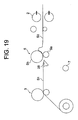
- the time from when the tail end of the preceding strip S 1 has gone through the coiling pinch rolls 105 to when the leading end of the following strip S 2 is bitten by the coiling pinch rolls 105 is as short as about 0.3 second. Therefore, if the leading end of the following strip S 2 is bitten by the coiling pinch rolls 105 when the rotational speed of the coiling pinch rolls 105 is lower than the sheet speed V s of the following strip S 2 as described above, the strip feed speed of the coiling pinch rolls 105 becomes lower than the sheet speed of the following strip S 2 , so that, as shown in Figure 19, the leading end or the following strip S 2 is oversupplied on the entrance side of the coiling pinch rolls 5.
- a deceleration-side torque limit T max (N ⁇ m) is set on the motor 117, which is the driving unit for the coiling pinch rolls 105, by which the motor 117 is controlled by the speed controller 120 so that the load torque of the motor 117 does not exceed the deceleration-side torque limit T max .
- the value of the torque limit T max such that when the leading end of the following strip S 2 is bitten by the coiling pinch rolls 105, the rotational speed of the coiling pinch rolls 105 is not lower than the sheet speed V s of the following strip S 2 as shown in Figure 6 can be determined beforehand as described below.
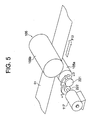
- the value of the torque limit T max to be set on the motor 117 for driving the lower pinch roll 105a will be explained with reference to Figure 5 taking a case where the lower pinch roll 105a of the coiling pinch rolls 105 is driven as an example.
- FIG. 5 shows a state in which the preceding strip S 1 is pressed by the pinch rolls 105.
- the sheet speed V s of the preceding strip S 1 is higher than the preset sheet speed V p2 of the lower pinch roll 105a, so that the lower pinch roll 105a is subjected to a force of F (N) from the preceding strip S 1 , and the motor 117 produces a torque T M (N ⁇ m) against this force.
- Equation (14) a dynamic equation of Equation (14) holds between the motor 117 and the gear 222.
- T M(t) - T (t) J 1 d ⁇ 1 dt
- Equation (16) Integration of Equation (15) yields the following Equation (16).
- ⁇ t 1 and ⁇ t 2 are the angular velocities of the lower pinch roll 105a at times t 1 and t 2 , respectively.
- F(t) is equal to zero.
- the minus sign of ⁇ means deceleration, and the plus sign thereof means acceleration.
- Equation (16) is expressed by the following equation (16A).
- T M(t) T max , by which the following equation (17) holds.
- Equation (17) the change amount ⁇ of the lower pinch roll time t 2 after the tail end of the preceding strip S 1 goes through the pinch rolls is expressed by the following equation (18).
- ⁇ T max . t 2 J 1 + J 2 . i 2
- T max for preventing the occurrence of oversupplying of the leading end of the following strip S 2 on the entrance side of the coiling pinch rolls 105 has only to satisfy the relationship of the following equation (20-4) from Equations (18) and (19).
- the deceleration-side torque limit T max is set on the motor 117 for driving the coiling pinch rolls 105 beforehand in this manner, while the coiling pinch rolls 105 presses the preceding strip S 1 after the strip is cut, the load torque on the deceleration side of the motor 117 created based on a speed difference between the target coiling speed V m of the preceding strip S 1 (the preset coiling speed of the downstream coiler 104) and the target sheet speed V p2 of the coiling pinch rolls 105 does not become excessive. Even immediately after the tail end of the preceding strip S 1 goes through the coiling pinch rolls 105, the rotational speed of the coiling pinch rolls 105 does not become lower than the sheet speed V s of the following strip S 2 .
- the tension reference given to the strip when the strip is coiled that is, the tension reference preset properly so as to correspond to the coiling temperature condition in coiling, the steel type of strip to be coiled, or the like is generally given in advance, and tension control is carried out in coiling by producing a rotational torque on the mandrel in coiling, which torque is such that a tension having a value equal to the tension reference can be given to the strip.
- a strip sent from the finishing mill is coiled by a plurality of mandrels alternately after being cut. Therefore, the time from coiling finish to coiling start of next strip per one mandrel is short, so that a coil (strip) having been coiled must be removed in the shortest possible time, and preparation for next coiling must be completed in a short time. For this purpose, it is necessary to stop the rotation of mandrel in a short time after the completion of coiling.
- the wrapper roll (pressing roll) is brought into contact with the strip surface coiled in a coil shape before the completion of coiling, the wrapper roll produces a torque such as to hinder the rotation of mandrel during coiling operation, so that the speed of the mandrel itself is undesirably decreased. As a result, a looseness of strip occurs between the wrapper roll and the pinch roll, so that a phenomenon of oversupplying of strip takes place.
- the rotation control of the motor 32 for the mandrel 2 lying at the coiling finish position is changed over from the torque control having been carried out to the rotational speed control.
- the changeover to the rotational speed control may be effected at timing when the strip shear 5 is operated.
- an upper limit value of the rotational speed may be set in advance so that when the actual rotational speed reaches the aforementioned value, the changeover to the speed control is effected automatically.
- the wrapper rolls 19 are arranged at equal intervals along the outer periphery of the coil. They are provided retractably with respect to the mandrel 2 via a hydraulic pump and a hydraulic cylinder provided with a servo valve (both not shown), and is capable of being rotated by a driving power source (not shown). In this embodiment, after the mandrel 2 is changed over to the rotational speed control at the time when the cutting operation is performed, the wrapper rolls 19 are brought into contact with the outer peripheral surface of coil to brake the coil.
- the wrapper rolls 19 also function as a guide when the coiling operation of strip is started by the mandrel 2. Also, the relative position of the wrapper coil 19 with respect to the coil may be detected by using a position detector (not shown) to increase the accuracy of contact with the coil.
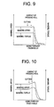
- Figure 9 shows the case where the torque control was continued
- Figure 10 shows the case where the torque control was switched to the rotational speed control.
- a decrease in rotational speed of mandrel when the wrapper rolls 19 come into contact with the coil is shown definitely.
- the control is changed over to the speed control at the time of strip cutting as shown in Figure 10, it is found that the decrease in rotational speed of mandrel is less, and the coil is not loosened.
- the rotational speed of the mandrel 2 be higher than the transfer speed of the preceding strip S 1 .
- the reason for this is that when the mandrel 2 is switched from the torque control to the rotational speed control, by setting the target of the speed control value so as to be somewhat higher the actual speed at that time, the mandrel 2 can surely pull the strip.
- the wrapper rolls 19 can be brought into contact with the coil while the mandrel 2 is subjected to speed control, and also the wrapper rolls 19 can quickly start an operation for braking the rotation of the coil.
- the mandrel 2 is subjected to torque control so that the strip coiled around the mandrel 2 is pulled with a predetermined coiling tension, by which coiling is performed. Thereafter, the strip is cut by the strip shear 5.
- the torque control of the mandrel 2 is continued.
- the coiling operation is continued in a state in which a tension is given to the strip by the pinch rolls 17 and the mandrel 2.
- the strip tension is decreased by 4F by bringing four wrapper rolls 19 into contact with the outer peripheral surface of coil, so that the preset value of the tension has only to be made higher by a value not lower than 4F when the wrapper rolls 19 are brought into contact with the coil.
- the pressing force applied to the strip by the upper pinch roll 105b is improper when the offset angle of the upstream coiling pinch rolls 105 is changed, for a thin strip, the tail end of the preceding strip S 1 coiled by the downstream coiler 104 cannot be held sufficiently between the upstream coiling pinch rolls 105. Therefore, the tail end of the preceding strip S 1 comes off from the upstream coiling pinch rolls 105 and is oversupplied, and hits the triangular gate 128, so that breakage of tail end may occur. For a thick strip, in some cases, the following strip S 2 cannot be introduced to the upstream coiler 101 correctly.
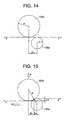
- Figure 14 shows a state in which the lower pinch roll 105a is retracted to the upstream side by an offset amount of ⁇ L with respect to the upper pinch roll 105b.
- Figure 15 shows a state in which after the lower pinch roll 105a is offset, the upper pinch roll 105b is pressed down with a pressing force P.
- a product P ⁇ x of the pressing force P of the pinch rolls 105 times a vertical displacement ⁇ x of the pinch roll 105 caused by the pressing force P means work done by the pressing force P.
- bending deformation is applied to the strip along the outer peripheral surface of the lower pinch roll 105a on the entrance side of the pinch rolls 105, and re-bending deformation along the lower pinch roll 105a by the bending deformation and re-bending deformation along the outer peripheral surface of the upper pinch roll 105b by the bending deformation are applied on the delivery side of the pinch rolls 105.
- the bending work done when a bend of a bending length 1 is created with a radius of curvature R by a bending moment M B produced on the strip is expressed as M B ⁇ (l/R).
- the work for effecting bending deformation of the strip along the outer peripheral surface of the lower pinch roll 105a is expressed as M B ⁇ (l a /R L ), and the re-bending deformation along the lower pinch roll 105a by the bending deformation on the delivery side of the pinch rolls 105, the bending deformation of strip along the outer peripheral surface of the upper pinch roll 105b, and the work for effecting the re-bending deformation along the outer
- M B can be expressed by the following equation (24).
- M B (1/6) ⁇ B ⁇ t 2 ⁇ w
- ⁇ B is the yield stress of strip
- t is the thickness of strip
- w is the width of strip.
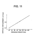
- Figure 11 shows the relationship between the pressing force of the upper pinch roll and the displacement in the downward direction of the upper pinch roll. For this relationship, the inclination is determined according to the size of pinch roll, the material and size of strip, or the like.
- Equation (23) is expressed by the following equation (25), and the following equation (26) holds from Equations (25) and (24).
- 1 2 ⁇ P 0 ⁇ x-F ⁇ u 2M B ⁇ (l a /R L )+(l b /R U ) ⁇
- the displacement ⁇ x and ⁇ u can be calculated geometrically.
- the yield stress ⁇ B of the strip is a value determined according to material, and the thickness t and the width w of the strip is determined according to the treated material. Therefore, if the tension F of the strip is determined from the rotational speed of the coiler and the rotational speed of the pinch rolls, the optimum pressing force P can be calculated.
- the pressing force of the coiling pinch roll is set at a value not lower than P 0 determined by the above-described equation (26).
- Figures 12 and 13 are charts showing the actual pressing force and the cylinder position reference for pressing down the pinch roll.
- Figure 12 shows a case where the pressing force setting in this embodiment is not performed, and Figure 13 shows this embodiment.
- the pressing force suddenly decreases to a no-load condition when the preceding strip comes off from the pinch rolls. If the pressing force decreases, as shown in Figure 12, the cylinder position reference acts in the direction such that the pressing force is kept to operate the pinch roll in the pressing direction. Therefore, there is the possibility of occurring defective biting of the following strip.
- an effect can be achieved that the preceding strip can be prevented from being oversupplied on the delivery side of the coiling pinch rolls, and also the leading end of the following material can be prevented from being oversupplied on the entrance side of the coiling pinch rolls.
- the relationship between the preset coiling speed V m of the mandrel after the tail end of the strip coiled by the mandrel via the coiling pinch rolls, the target speed V p of the coiling pinch rolls at the time of the cutting operation, and the sheet speed V s of the following material immediately after the cutting operation is set so that V m > V p > V s .
- the relationship between the target speed V p1 of the second coiling pinch rolls when the tail end of the strip coiled by the downstream mandrel via the second coiling pinch rolls disposed on the entrance side of the downstream mandrel is cut, the target speed V p2 of the first coiling pinch rolls disposed on the delivery side of the strip shear, the target sheet speed V s of the following material immediately after the cutting operation, and the preset coiling speed V m of the downstream mandrel is set so that V m > V p1 > V p2 > V s .
- the strip is pressed by the upper pinch roll of the first coiling pinch rolls in the state in which the speed of the lower pinch roll is made lower than the target sheet speed V s of the following material until the actual torque value of the lower pinch roll becomes the preset value, and the pressing force at this time is made the preset pressing force of the offset upper pinch roll applied to the strip, by which the tail end of the strip coiled by the downstream mandrel can be held properly by the first coiling pinch rolls. Therefore, an effect can be achieved that the slip of the strip tail end with respect to the upstream coiling pinch rolls can surely be eliminated.
- P F( ⁇ u/ ⁇ x) + 2(M B / ⁇ x) ⁇ (l a /r) + (l b /R) ⁇ .
- the strip coiling control carried out by the mandrel is changed over from torque control to rotational speed control, and thereafter the pressing roll is pressed on the strip to be coiled into a coil shape to stop the rotation of the mandrel.
- the torque control of strip is carried out by the mandrel to increase the tension of strip, and thereafter the pressing roll is pressed on the strip to be coiled into a coil shape to stop the rotation of the mandrel.
- the deceleration-side torque limit of the driving unit for the coiling pinch rolls is set so that the circumferential speed of the coiling pinch rolls is higher than the transfer speed of the following material when the leading end of the following material is bitten by the coiling pinch rolls disposed on the delivery side of the strip shear after the strip is cut by the strip shear.
Landscapes
- Engineering & Computer Science (AREA)
- Mechanical Engineering (AREA)
- Winding, Rewinding, Material Storage Devices (AREA)
- Ropes Or Cables (AREA)
- Yarns And Mechanical Finishing Of Yarns Or Ropes (AREA)
- Investigation Of Foundation Soil And Reinforcement Of Foundation Soil By Compacting Or Drainage (AREA)
- Windings For Motors And Generators (AREA)
- Winding Of Webs (AREA)
- Replacement Of Web Rolls (AREA)
Applications Claiming Priority (3)
| Application Number | Priority Date | Filing Date | Title |
|---|---|---|---|
| JP8207499 | 1999-03-25 | ||
| JP11082074A JP2000271641A (ja) | 1999-03-25 | 1999-03-25 | ストリップの巻取方法 |
| PCT/JP1999/005198 WO2000058039A1 (fr) | 1999-03-25 | 1999-09-22 | Procede d'enroulement de bandes |
Publications (3)
| Publication Number | Publication Date |
|---|---|
| EP1121994A1 true EP1121994A1 (de) | 2001-08-08 |
| EP1121994A4 EP1121994A4 (de) | 2003-05-28 |
| EP1121994B1 EP1121994B1 (de) | 2005-11-23 |
Family
ID=13764340
Family Applications (1)
| Application Number | Title | Priority Date | Filing Date |
|---|---|---|---|
| EP99944792A Expired - Lifetime EP1121994B1 (de) | 1999-03-25 | 1999-09-22 | Verfahren zum wickeln von band |
Country Status (8)
| Country | Link |
|---|---|
| EP (1) | EP1121994B1 (de) |
| JP (1) | JP2000271641A (de) |
| KR (1) | KR100521953B1 (de) |
| CN (1) | CN1123407C (de) |
| AT (1) | ATE310594T1 (de) |
| CA (1) | CA2332953C (de) |
| DE (1) | DE69928559T2 (de) |
| WO (1) | WO2000058039A1 (de) |
Cited By (2)
| Publication number | Priority date | Publication date | Assignee | Title |
|---|---|---|---|---|
| WO2007045636A1 (de) * | 2005-10-17 | 2007-04-26 | Siemens Aktiengesellschaft | Betriebsverfahren für eine haspelanordnung zum aufhaspeln eines bandes und hiermit korrespondierende gegenstände |
| CN102039330A (zh) * | 2010-10-16 | 2011-05-04 | 山西太钢不锈钢股份有限公司 | 热连轧薄板卷取设备的参数设定及其卷取方法 |
Families Citing this family (26)
| Publication number | Priority date | Publication date | Assignee | Title |
|---|---|---|---|---|
| KR100787586B1 (ko) * | 2001-07-11 | 2007-12-21 | 주식회사 포스코 | 엔트리가이드의 스트립 선단부 유도장치 |
| KR100530333B1 (ko) * | 2001-12-18 | 2005-11-22 | 주식회사 포스코 | 열연 권취형상 및 폭 넥킹 방지를 위한 사상압연기의스피드 제어방법 |
| DE10208964A1 (de) * | 2002-02-28 | 2003-09-18 | Sms Demag Ag | Umlenkeinrichtung für ein Band in einer Haspelanlage |
| CN101716597B (zh) * | 2009-12-15 | 2012-05-30 | 中冶南方(武汉)自动化有限公司 | 冷轧带钢生产机组带尾剪切时防止带尾碎片卡剪的方法 |
| EP2512700B1 (de) * | 2009-12-17 | 2017-05-24 | Primetals Technologies Germany GmbH | Verfahren zum betrieb einer wickeltrommel eines haspelofens für ein reversierend arbeitendes warmwalzwerk, steuer- und/oder regeleinrichtung und reversierend arbeitendes warmwalzwerk |
| CN101912874B (zh) * | 2010-07-14 | 2012-07-04 | 宁波钢铁有限公司 | 一种防止供冷轧基板用热轧低碳带钢卷取拉窄的制造方法 |
| CN102489544B (zh) * | 2011-12-19 | 2014-08-13 | 中冶南方(武汉)自动化有限公司 | 用于冷轧处理线开卷机高速甩尾的控制方法 |
| CN102654755A (zh) * | 2012-04-27 | 2012-09-05 | 本钢板材股份有限公司 | 为轧机活套提供启动信号的方法 |
| CN103372583B (zh) * | 2012-04-28 | 2015-06-17 | 宝山钢铁股份有限公司 | 一种热轧卷取张力的控制方法 |
| DE102012224351A1 (de) * | 2012-12-21 | 2014-06-26 | Sms Siemag Ag | Verfahren und Vorrichtung zum Wickeln eines Metallbandes |
| CN103962414B (zh) * | 2013-01-28 | 2015-10-28 | 宝山钢铁股份有限公司 | 一种卷取机助卷辊阶梯速度控制方法及其控制系统 |
| DE102014213537A1 (de) | 2013-12-05 | 2015-06-11 | Sms Siemag Ag | Verfahren und Vorrichtung zur Herstellung eines metallischen Bandes im Gießwalzverfahren |
| CN104259204B (zh) * | 2014-09-15 | 2016-08-24 | 首钢京唐钢铁联合有限责任公司 | 一种改善超薄带钢取穿带的工艺优化方法 |
| CN104624723B (zh) * | 2015-01-30 | 2016-08-24 | 广西柳州银海铝业股份有限公司 | 带材卷取过程中活动夹送辊的控制方法 |
| CN104815869B (zh) * | 2015-04-15 | 2017-01-04 | 广西柳州银海铝业股份有限公司 | 带材卷取过程中压尾辊的控制方法 |
| CN104959398B (zh) * | 2015-05-25 | 2016-09-21 | 山西太钢不锈钢股份有限公司 | 极限规格304不锈钢的卷取方法 |
| CN107020309B (zh) * | 2016-01-29 | 2019-03-29 | 宝山钢铁股份有限公司 | 一种卷取机夹送辊跟踪精度的校正装置及校正方法 |
| CN105665452B (zh) * | 2016-02-15 | 2017-12-26 | 山西太钢不锈钢股份有限公司 | 一种消除热轧带钢头部压痕的方法 |
| CN106493172B (zh) * | 2016-11-04 | 2018-08-03 | 北京首钢自动化信息技术有限公司 | 一种解决薄带钢在卷取穿带过程中产生褶皱的方法 |
| CN106743894B (zh) * | 2016-11-18 | 2018-12-14 | 首钢京唐钢铁联合有限责任公司 | 一种开卷机的张力控制方法 |
| CN107199246B (zh) * | 2017-07-26 | 2019-10-29 | 河钢股份有限公司承德分公司 | 热轧薄规格带钢卷取方法 |
| CN109663834A (zh) * | 2018-11-14 | 2019-04-23 | 包头钢铁(集团)有限责任公司 | 一种改善连续镀锌线卷曲机带尾甩偏的控制方法 |
| CN112756427A (zh) * | 2020-12-28 | 2021-05-07 | 包头钢铁(集团)有限责任公司 | 一种镀锌机组防止出口滚筒剪与夹送辊之间堆带的控制方法 |
| CN113042540B (zh) * | 2021-03-24 | 2022-08-19 | 山西太钢不锈钢精密带钢有限公司 | 一种极薄钢带卷取张力控制方法 |
| CN115156333B (zh) * | 2022-07-04 | 2025-09-26 | 宁波祥路中天新材料科技股份有限公司 | 一种阻尼裁剪装置 |
| CN115351111B (zh) * | 2022-07-27 | 2025-08-01 | 无锡市龙泰精密弹性材料有限公司 | 一种恒力弹簧用不锈钢带生产方法 |
Family Cites Families (9)
| Publication number | Priority date | Publication date | Assignee | Title |
|---|---|---|---|---|
| JPH082458B2 (ja) * | 1988-12-15 | 1996-01-17 | 三菱重工業株式会社 | 連続圧延ラインのピンチロール装置 |
| JP2923021B2 (ja) * | 1990-09-26 | 1999-07-26 | 株式会社日立製作所 | 熱間連続圧延機におけるストリップ巻取装置 |
| JPH05154550A (ja) * | 1991-12-09 | 1993-06-22 | Kawasaki Steel Corp | コイルの巻取り停止方法 |
| JP3124139B2 (ja) * | 1992-12-22 | 2001-01-15 | 川崎製鉄株式会社 | 鋼帯の搬送速度制御方法 |
| JPH0775825A (ja) * | 1993-09-06 | 1995-03-20 | Nippon Steel Corp | 熱間圧延設備のロールギャップ制御装置 |
| JPH07236916A (ja) * | 1994-02-28 | 1995-09-12 | Nisshin Steel Co Ltd | 連続冷間圧延機の出側張力制御方法および装置 |
| JPH0890058A (ja) * | 1994-09-21 | 1996-04-09 | Kawasaki Steel Corp | 巻取機ピンチロールの制御方法 |
| JP3310856B2 (ja) * | 1996-04-19 | 2002-08-05 | 三菱重工業株式会社 | 熱延帯鋼の巻き取り方法及び熱延帯鋼の巻き取り装置 |
| JP3387393B2 (ja) * | 1996-10-30 | 2003-03-17 | 日本鋼管株式会社 | 連続処理ラインの能率向上方法及び装置 |
-
1999
- 1999-03-25 JP JP11082074A patent/JP2000271641A/ja active Pending
- 1999-09-22 CN CN99806568A patent/CN1123407C/zh not_active Expired - Fee Related
- 1999-09-22 EP EP99944792A patent/EP1121994B1/de not_active Expired - Lifetime
- 1999-09-22 KR KR10-2000-7013099A patent/KR100521953B1/ko not_active Expired - Fee Related
- 1999-09-22 WO PCT/JP1999/005198 patent/WO2000058039A1/ja not_active Ceased
- 1999-09-22 DE DE69928559T patent/DE69928559T2/de not_active Expired - Lifetime
- 1999-09-22 AT AT99944792T patent/ATE310594T1/de active
- 1999-09-22 CA CA002332953A patent/CA2332953C/en not_active Expired - Fee Related
Non-Patent Citations (2)
| Title |
|---|
| No further relevant documents disclosed * |
| See also references of WO0058039A1 * |
Cited By (2)
| Publication number | Priority date | Publication date | Assignee | Title |
|---|---|---|---|---|
| WO2007045636A1 (de) * | 2005-10-17 | 2007-04-26 | Siemens Aktiengesellschaft | Betriebsverfahren für eine haspelanordnung zum aufhaspeln eines bandes und hiermit korrespondierende gegenstände |
| CN102039330A (zh) * | 2010-10-16 | 2011-05-04 | 山西太钢不锈钢股份有限公司 | 热连轧薄板卷取设备的参数设定及其卷取方法 |
Also Published As
| Publication number | Publication date |
|---|---|
| WO2000058039A1 (fr) | 2000-10-05 |
| EP1121994A4 (de) | 2003-05-28 |
| CA2332953A1 (en) | 2000-10-05 |
| KR100521953B1 (ko) | 2005-10-14 |
| KR20010043743A (ko) | 2001-05-25 |
| DE69928559D1 (de) | 2005-12-29 |
| DE69928559T2 (de) | 2006-06-01 |
| CN1123407C (zh) | 2003-10-08 |
| JP2000271641A (ja) | 2000-10-03 |
| CN1303323A (zh) | 2001-07-11 |
| EP1121994B1 (de) | 2005-11-23 |
| CA2332953C (en) | 2004-08-24 |
| ATE310594T1 (de) | 2005-12-15 |
Similar Documents
| Publication | Publication Date | Title |
|---|---|---|
| EP1121994B1 (de) | Verfahren zum wickeln von band | |
| US4798071A (en) | Seamless tube production | |
| US8261589B2 (en) | Method and device for coiling thin metal strip, especially hot rolled or cold-rolled thin steel strip | |
| US6301946B1 (en) | Strip coiling method | |
| JPH0513723B2 (de) | ||
| JP6991232B2 (ja) | 結合された連続鋳造および金属ストリップ熱間圧延プラント | |
| JP2020509937A (ja) | 結合された連続鋳造および金属ストリップ熱間圧延プラント | |
| US9238259B2 (en) | Method and device for winding hot-rolled strip | |
| US4289011A (en) | Continuous pipe rolling process | |
| JPH11197741A (ja) | 金属帯の巻き取り方法 | |
| US4388816A (en) | Method and apparatus for rolling a length of metal bar or wire | |
| CN114951271B (zh) | 一种金属带材轧制装置及轧制方法 | |
| JPH07185608A (ja) | 長い素管を圧延するコールドピルガーミル | |
| JP3265055B2 (ja) | サイドガイドの制御方法 | |
| JP3004780B2 (ja) | 圧延材の先端曲り矯正方法及び装置並びに熱間薄板圧延設備 | |
| JPS58163524A (ja) | 鋼板巻取機制御装置 | |
| JPH10263613A (ja) | 可逆式冷間圧延機の圧延方法と圧延制御装置 | |
| JP2003220401A (ja) | 熱間圧延方法および熱間圧延ライン | |
| JPS6345887B2 (de) | ||
| US5860311A (en) | Method to guide the strip between the stands in a rolling mill finishing train and relative device | |
| JPH0671636B2 (ja) | 板ばねの製造装置および板ばねの製造方法 | |
| JP3846318B2 (ja) | コイルボックスでの巻き取り方法 | |
| JP2001179333A (ja) | 金属帯の巻取装置の制御方法 | |
| JPH0775824A (ja) | 捲取張力制御装置 | |
| JP3276279B2 (ja) | ピンチロールの制御装置 |
Legal Events
| Date | Code | Title | Description |
|---|---|---|---|
| PUAI | Public reference made under article 153(3) epc to a published international application that has entered the european phase |
Free format text: ORIGINAL CODE: 0009012 |
|
| 17P | Request for examination filed |
Effective date: 20001115 |
|
| AK | Designated contracting states |
Kind code of ref document: A1 Designated state(s): AT DE FR GB SE |
|
| A4 | Supplementary search report drawn up and despatched |
Effective date: 20030410 |
|
| RAP1 | Party data changed (applicant data changed or rights of an application transferred) |
Owner name: JFE STEEL CORPORATION |
|
| 17Q | First examination report despatched |
Effective date: 20040413 |
|
| GRAP | Despatch of communication of intention to grant a patent |
Free format text: ORIGINAL CODE: EPIDOSNIGR1 |
|
| GRAS | Grant fee paid |
Free format text: ORIGINAL CODE: EPIDOSNIGR3 |
|
| GRAA | (expected) grant |
Free format text: ORIGINAL CODE: 0009210 |
|
| AK | Designated contracting states |
Kind code of ref document: B1 Designated state(s): AT DE FR GB SE |
|
| REG | Reference to a national code |
Ref country code: GB Ref legal event code: FG4D |
|
| REG | Reference to a national code |
Ref country code: SE Ref legal event code: TRGR |
|
| REF | Corresponds to: |
Ref document number: 69928559 Country of ref document: DE Date of ref document: 20051229 Kind code of ref document: P |
|
| ET | Fr: translation filed | ||
| PLBE | No opposition filed within time limit |
Free format text: ORIGINAL CODE: 0009261 |
|
| STAA | Information on the status of an ep patent application or granted ep patent |
Free format text: STATUS: NO OPPOSITION FILED WITHIN TIME LIMIT |
|
| 26N | No opposition filed |
Effective date: 20060824 |
|
| PGFP | Annual fee paid to national office [announced via postgrant information from national office to epo] |
Ref country code: AT Payment date: 20140827 Year of fee payment: 16 Ref country code: GB Payment date: 20140917 Year of fee payment: 16 Ref country code: SE Payment date: 20140911 Year of fee payment: 16 |
|
| PGFP | Annual fee paid to national office [announced via postgrant information from national office to epo] |
Ref country code: FR Payment date: 20140906 Year of fee payment: 16 |
|
| REG | Reference to a national code |
Ref country code: SE Ref legal event code: EUG |
|
| REG | Reference to a national code |
Ref country code: AT Ref legal event code: MM01 Ref document number: 310594 Country of ref document: AT Kind code of ref document: T Effective date: 20150922 |
|
| GBPC | Gb: european patent ceased through non-payment of renewal fee |
Effective date: 20150922 |
|
| PG25 | Lapsed in a contracting state [announced via postgrant information from national office to epo] |
Ref country code: SE Free format text: LAPSE BECAUSE OF NON-PAYMENT OF DUE FEES Effective date: 20150923 |
|
| REG | Reference to a national code |
Ref country code: FR Ref legal event code: ST Effective date: 20160531 |
|
| PG25 | Lapsed in a contracting state [announced via postgrant information from national office to epo] |
Ref country code: GB Free format text: LAPSE BECAUSE OF NON-PAYMENT OF DUE FEES Effective date: 20150922 |
|
| PG25 | Lapsed in a contracting state [announced via postgrant information from national office to epo] |
Ref country code: FR Free format text: LAPSE BECAUSE OF NON-PAYMENT OF DUE FEES Effective date: 20150930 Ref country code: AT Free format text: LAPSE BECAUSE OF NON-PAYMENT OF DUE FEES Effective date: 20150922 |
|
| PGFP | Annual fee paid to national office [announced via postgrant information from national office to epo] |
Ref country code: DE Payment date: 20170920 Year of fee payment: 19 |
|
| REG | Reference to a national code |
Ref country code: DE Ref legal event code: R119 Ref document number: 69928559 Country of ref document: DE |
|
| PG25 | Lapsed in a contracting state [announced via postgrant information from national office to epo] |
Ref country code: DE Free format text: LAPSE BECAUSE OF NON-PAYMENT OF DUE FEES Effective date: 20190402 |