EP1122064A2 - Procédé et dispositif pour conduite des feuilles dans une machine rotative - Google Patents
Procédé et dispositif pour conduite des feuilles dans une machine rotative Download PDFInfo
- Publication number
- EP1122064A2 EP1122064A2 EP01101477A EP01101477A EP1122064A2 EP 1122064 A2 EP1122064 A2 EP 1122064A2 EP 01101477 A EP01101477 A EP 01101477A EP 01101477 A EP01101477 A EP 01101477A EP 1122064 A2 EP1122064 A2 EP 1122064A2
- Authority
- EP
- European Patent Office
- Prior art keywords
- cylinder
- blanket
- printing
- sheet
- nozzle system
- Prior art date
- Legal status (The legal status is an assumption and is not a legal conclusion. Google has not performed a legal analysis and makes no representation as to the accuracy of the status listed.)
- Granted
Links
Images


Classifications
-
- B—PERFORMING OPERATIONS; TRANSPORTING
- B41—PRINTING; LINING MACHINES; TYPEWRITERS; STAMPS
- B41F—PRINTING MACHINES OR PRESSES
- B41F25/00—Devices for pressing sheets or webs against cylinders, e.g. for smoothing purposes
Definitions
- the invention relates to a method and an apparatus for Sheet guiding in a rotary printing machine according to the generic terms of main and secondary claim.
- a sheet guiding device is from EP 0 306 682 A2 known.
- the device consists essentially of two with Blown air acted on blow strips before and after the formed by a blanket cylinder and an impression cylinder Pressure zone over the cylinder width arranged axially parallel are.
- the front blow bar in the conveying direction is in the gusset-shaped space above the incoming arch between Blanket cylinder and impression cylinder arranged.
- the Blown air flow is on the blanket cylinder, in the Printing zone itself as well as on top of that on the impression cylinder the bow guided in the gripper closure.
- the invention primarily describes the sheet guiding device in printing mode (print on position). It is also in another operating position in printing practice, such that when the blanket cylinder is switched off (print from position) the blown air operation is maintained, for example when checking the paper flow or when a printing unit is not involved in printing.
- the substrate is then in the Gripper closes on the pressure cylinder through the pressure gap (contactless to the inactive blanket cylinder) using blowing air funded by the appropriate printing unit.
- From DE 43 18 777 C2 is a sheet guiding device for a Printing unit not involved in printing with an existing gap between blanket cylinder and impression cylinder known.
- a blow pipe with nozzles is arranged in the pressure zone, whereby each a nozzle of the upstream blowpipe a nozzle of downstream blow pipe.
- blow the Nozzles of the upstream blow pipe a constant blow air jet against the blanket cylinder in front of the printing zone is deflected, and the nozzles of the downstream blowpipe blow a constant jet of blowing air against the pressure cylinder, so the sheet material against the conveying direction is crossed out.
- a blowing nozzle which blows an air jet onto the arc Substrate aligns and thereby a spread effect achieved.
- the blow nozzles are parallel in front of the pressure gap axis lying to the axis of the impression cylinder is pendulum stored and can be coupled with a drive, which in Working cycle of the printing machine swinging the blowing nozzle in Direction of conveyance of the substrate moves back and forth.
- the result of the swinging movement is a relaxation and even Placing the sheet material on the sheet guide cylinder, especially with thin substrates with low Weight per unit area, certainly not guaranteed. It is in a training the air flow of the blow nozzles in the work cycle of the presses controllable.
- the invention has for its object a method and a device for sheet guidance in a rotary printing press to create that avoids the disadvantages mentioned, which in particular a more even guidance of the printing material on a sheet guide cylinder, especially one Printing cylinder, allowed and cheaper energy consumption of compressed air.
- the task is characterized by the training characteristics of main and Secondary claim solved. Further training results from the Dependent claims.
- a first advantage of the invention is based on the fact that the device has a nozzle system which in the area a pressure zone by a plurality of over the maximum Format width of the printing material arranged annular gap nozzles is formed.
- a nozzle system is with compressed air operable, which at very high speed to the Annular gap nozzles emerges.
- This nozzle system breaks in the high Measurements of ambient air, which are bundled with the compressed air exits and emerges as a jet flow from the annular gap nozzles the sheet material works. Because the annular gap of the nozzle system are very narrow and preferably adjustable and additionally the Existing ambient air is used is the energy consumption relatively low in compressed air.
- annulus preferred are adjustable is the one acting on the substrate Jet pressure considering the basis weight and / or the rigidity and / or the print subject of the sheet material adjustable. This results in adjustable Annular gap nozzles have the advantage that viewed across the format width different jet flows on the sheet material Act.
- the nozzle system has a low Sound level generated, so the noise level for the operator or the environment can be reduced.
- the nozzle system can be operated continuously (with start-up) of the printing press in all operating positions (in printing on position or printing off position), preferably in cyclical operation.
- a device for sheet guiding with a nozzle system that can be operated in cycles is arranged in front of a printing zone formed from the blanket / form cylinder and the sheet guiding cylinder, preferably the printing cylinder.
- This device has, at least in a gusset-shaped space in the conveying direction of the sheet-like printing material in front of the printing zone, a nozzle system with annular gap nozzles which is arranged axially parallel to the sheet guide cylinder and which is functionally connected to a compressed air system and a device for clock control, for example a switching valve.
- the direction of flow of the nozzle system arranged in front of the printing nip is preferably completely or partially directed towards the outer surface of the blanket cylinder / forme cylinder.
- the nozzle system with its direction of flow on the lateral surface of the sheet guiding cylinder leading the sheet, for example, the impression cylinder.
- the sheet format is taken into account when controlling the pulsed compressed air, such that blowing the trailing edge of the sheet (end of the sheet) on the sheet guide cylinder through a nozzle system independently of the respective operating position (print on position, print off position) ) is avoidable.
- the device for clock control of the compressed air is preferably functionally connected to a central machine control. Depending on the format, this machine control system can be used to implement the cycle operation of the nozzle system, preferably in an angle-correlated manner. It is also advantageous that the nozzle system can be controlled quickly in the compressed air mode, since short switching times can be achieved.
- the nozzle system is one has low energy consumption of compressed air.
- Compressed air can be reached at high speed, which sweeps in large amounts of ambient air and thus one bundled air flow with high jet pressure as a reinforcing effect can be generated.
- Ambient air becomes a cheaper energy consumption Compressed air achieved.
- Another training course is in addition to that in the funding direction a sheet guiding device arranged in front of the printing zone another device for sheet guidance mirror image analog to the upstream sheet guiding device with a nozzle system with annular gap nozzles, a device for cycle control, e.g. a switching valve, and a compressed air system in functional connection.
- a device for cycle control e.g. a switching valve
- a compressed air system in functional connection.
- nozzle systems can be pivoted slidable on a crossbar and in the axial direction of the crossbar are arranged.
- a sheet-fed rotary printing machine is in a row construction shown.
- sheet holding systems e.g. Gripper systems, suction systems
- FIG. 1 a section of such a printing machine for inline finishing is shown. Only the last printing unit 1 with a plate cylinder 10, a blanket cylinder 11 and the printing cylinder 5 is shown as a sheet guiding cylinder.
- the plate cylinder 10 is assigned an inking unit and possibly a dampening unit, which will not be discussed in more detail here.
- the printing unit 1 is followed in the conveying direction 8 by a first coating unit 3, which is formed by a forme cylinder 11, an application roller 12 and a metering system 13, for example a chamber doctor blade.
- the form cylinder 11 is in turn assigned to the impression cylinder 5.
- the first coating unit 3 is assigned a dryer device 14, for example an infrared dryer, an adjacent printing cylinder 5 or an adjacent transfer cylinder 4.
- the dryer device 14 is followed in the conveying direction 8 by a second coating unit 3 with forme cylinder 11, applicator roller 12 and a metering system 13.
- the printing cylinders 5 of the printing units 1, coating units 13 and the drying unit 14 are connected to one another by means of transfer cylinders 4 for sheet transport.
- the second coating unit 3 is followed in the conveying direction 8 by a delivery arm 2, which supplies the sheet-like printing material to a delivery stack in a known manner by means of circulating conveyor systems 6 and stores it there.
- a Printing unit 1 and / or at least one coating unit 3 is in Conveying direction 8 upstream of the pressure zone 29 Nozzle system 7 arranged. 8 in the conveying direction is preferred after the pressure zone 29, a downstream nozzle system 9 is a mirror image (preferably structurally identical) to the nozzle system 7.
- the nozzle systems 7, 9 extend axially parallel in the longitudinal direction across the width of the sheet guide cylinder, here the Printing cylinder 5, and are made up of a plurality of annular gap nozzles 16 formed.
- the arrangement of the annular gap nozzles 16 in upstream nozzle system 7 is for arranging the annular gap nozzles 16 in the downstream nozzle system of any kind.
- the annular gap nozzles 16 preferably show the upstream one Nozzle system 7 in the direction of blanket / form cylinder 11 and Annular gap nozzles 16 of the downstream nozzle system 9 show in Towards printing cylinder 5.
- the annular gap nozzles 16 of the preceding nozzle system 7 point exclusively in the direction of the printing cylinder 5.
- the annular gap nozzles 16 of the nozzle system 7 point in the direction of the blanket / form cylinder 11 and in the direction of the printing cylinder 5.
- At least one annular gap nozzle 16 is directed onto the sheet guiding cylinder 5.
- the predominant part of the annular gap nozzles 16 is directed against the blanket / form cylinder 11 and a smaller proportion of the annular gap nozzles 16 points in the direction of the printing zone 29.
- the predominant proportion is directed against the blanket / form cylinder 11 and a proportion of each Annular gap nozzles 16 are directed towards the printing zone 29 and towards the sheet guiding cylinder 5.
- the annular gap nozzles 16 are on one in the side frames 21 fixed crossbar 15 preferably pivotable about the axis and arranged releasably in the axial direction.
- the Annular gap nozzles 16 of each nozzle system 7, 9 are each with a distribution channel 17 in functional connection.
- the distribution channel 17 is preferably in the middle opening feed channel 18 in functional connection.
- the Feed channel 18 is functionally connected to a compressed air source 20, one device for each nozzle system 7 or 9 for cycle control, preferably a controllable switching valve 19, is connected in between.
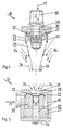
- Figures 4 and 5 are annular gap nozzles 16 in their basic Construction shown.
- Figure 4 shows an annular gap nozzle 16 with an externally arranged annular gap 22, however 5 shows an annular gap nozzle 16 with an inside Annular gap 22.
- the annular gap nozzle 16 has a base body 28 with a channel 30, which via the distribution channel 17th is in functional connection with the compressed air source 20.
- a cone 25 is releasably attached to the base body 28, e.g. screwed onto the base body 28.
- an external one Annular gap 22 arranged with the channel 30 in the base body 28 is in functional connection.
- the cone 25 is preferably with the base body 28 releasably connected by means of thread 32. about the thread 32 is self-locking or by means of the stop
- the annular gap 22 can be finely adjusted in its cross section.
- the base body 28 also has a channel 30 on which via the distribution channel 17 with the compressed air source 20 is in functional connection.
- an insert element 27 is detachably attached centrally, e.g. screwed to the base body 28.
- an internal one Annular gap 22 arranged with the channel 30 in the base body 28 is in functional connection.
- the insert element is preferred 27 with the base body 28 by means of thread 32 self-locking or releasably connected by means of a stop.
- the annular gap 22 is finely metered in its cross section adjustable.
- the base body 28 also has a suction opening 31 for the ambient air 24, which with an inside of the insert element 27 arranged centrally, with the Annular gap 22 functionally connected channel in function connection is.
- the nozzle systems 7, 9 are optionally available with annular gap nozzles 16 4 and / or 5 executable.
- the operation of the annular gap nozzles 16 is as follows: Compressed air is continuously fed from the compressed air source 20 to the controllable switching valve 19 of the respective nozzle system 7 or 9. Compressed air is supplied from the compressed air source 20 via the supply duct 18 and the distribution duct 17 into the duct 30 of the annular gap nozzle 16 and the compressed air is distributed within the duct 30 and passes through the annular gap 22.
- a gap flow 23 occurs after the annular gap 22, which due to the Coanda effect the contour of the Kegels 25 follows.
- the ambient air 24 becomes high Dimensions carried away and at the top of the cone 25 comes loose a bundled from gap flow 23 and ambient air 24 Jet flow 26 with high jet pressure from around the sheet guide to support.
- the working method of the nozzle systems 7, 9 is as follows. ever a preferably coupled to a machine control Switching valve 19 controls the compressed air supplied in cycles for the assigned nozzle system 7 or 9.
- the first switching valve 19 for the upstream nozzle system 7 controls the the jet stream 26 striking the sheet material such that only in the phase between the beginning and end of each the sheet guide cylinder (impression cylinder 5) guided sheet material the jet flow 26 from the annular gap nozzles 16 in Nozzle system 7 exits (intermittent operation). happenss the end of the Sheet material the pressure gap 29 becomes the jet flow 26 immediately interrupted.
- the jet flow 26 is at least against the blanket / Form cylinder 11 directed.
- the Jet flow 26 at least one annular gap nozzle 16 in the Pressure zone 29 be directed.
- the cycle operation of the nozzle system 7 is in printing mode with the blanket / forme cylinder turned on 11 or in the case of a blanket / Forme cylinder 11 with a gap in the pressure zone 29 between
- Blanket / form cylinder 11 and sheet guide cylinder 5 realizable.
- a nozzle system 9 downstream of the pressure zone 29 is provided, in this way, synchronized with the interrupted jet flow 26 of the upstream nozzle system 7, the compressed air via the preferably coupled with a machine control, second controllable switching valve 19 fed to the nozzle system 9, such that the jet flow 26 in the nozzle system 9 between Start and end of one on a sheet guide cylinder (impression cylinder 5) guided sheet material, especially up to End of the sheet material that hits it.
- the Jet flow 26 of the annular gap nozzles 16 is against the Sheet guide cylinder, here the impression cylinder 5, directed.
- the jet flow 26 of the nozzle system 7 arranged in front of the printing zone 29 is directed at least against the blanket / form cylinder 11 and emerges in the phase operation between the middle and end of the sheet material.
- the jet flow 26 of the nozzle system 9 arranged after the printing zone 29 is directed against the sheet guiding cylinder, here the printing cylinder 5, and emerges in cyclical operation in the phase between the middle and end of the sheet material.
- the nozzle systems 7, 9 upstream or downstream of the pressure zone 29 are arranged in combination and can be operated.
- at least one jet flow 26 directed against the blanket / form cylinder 11 emerges from the nozzle system 7 in cycles
- a jet flow 26 directed against the sheet guiding cylinder (impression cylinder 5) emerges from the nozzle system 9 in cycles.
- This mode of operation can be implemented in printing operation when the blanket / form cylinder 11 is on or when a blanket / form cylinder 11 is not involved in the printing, with a gap in the printing zone 29 between the blanket / form cylinder 11 and the sheet guiding cylinder 5 in order to guide the sheet on the sheet guiding cylinder 5 guided sheet material to support.
- the nozzle systems 7, 9 can be arranged individually and operated individually.
- the jet flows 26 are in cyclical operation between Start and end of one on the sheet guide cylinder 5 guided sheet material activated.
- the nozzle systems 7, 9 can be combined and operated in combination.
- the jet flow 26 of the upstream nozzle system 26 emerges first and is interrupted immediately when the end of the sheet material passes through the printing zone 29.
- the downstream nozzle system 9 is activated so that the jet flow 26 from the annular gap nozzles 16 strikes the sheet material and is switched off as it passes through the end of the sheet material.
- the cyclical operation of the jet flows 26 of the nozzle systems 7, 9 can be implemented in such a way that it overlaps.
- the upstream nozzle system 7 is activated first, and shortly before this nozzle system 7 is switched off, the downstream nozzle system 9 is already activated.
Landscapes
- Supply, Installation And Extraction Of Printed Sheets Or Plates (AREA)
- Separation, Sorting, Adjustment, Or Bending Of Sheets To Be Conveyed (AREA)
- Rotary Presses (AREA)
- Feeding Of Articles By Means Other Than Belts Or Rollers (AREA)
Applications Claiming Priority (2)
| Application Number | Priority Date | Filing Date | Title |
|---|---|---|---|
| DE10005391A DE10005391A1 (de) | 2000-02-07 | 2000-02-07 | Verfahren und Vorrichtung zur Bogenführung in einer Rotationsdruckmaschine |
| DE10005391 | 2000-02-07 |
Publications (3)
| Publication Number | Publication Date |
|---|---|
| EP1122064A2 true EP1122064A2 (fr) | 2001-08-08 |
| EP1122064A3 EP1122064A3 (fr) | 2002-06-26 |
| EP1122064B1 EP1122064B1 (fr) | 2008-02-27 |
Family
ID=7630133
Family Applications (1)
| Application Number | Title | Priority Date | Filing Date |
|---|---|---|---|
| EP01101477A Expired - Lifetime EP1122064B1 (fr) | 2000-02-07 | 2001-01-24 | Procédé et dispositif pour conduite des feuilles dans une machine rotative |
Country Status (3)
| Country | Link |
|---|---|
| EP (1) | EP1122064B1 (fr) |
| AT (1) | ATE387315T1 (fr) |
| DE (2) | DE10005391A1 (fr) |
Cited By (1)
| Publication number | Priority date | Publication date | Assignee | Title |
|---|---|---|---|---|
| CN100408331C (zh) * | 2006-08-02 | 2008-08-06 | 中国印钞造币总公司 | 印刷机橡皮布杂物自动清除装置 |
Families Citing this family (4)
| Publication number | Priority date | Publication date | Assignee | Title |
|---|---|---|---|---|
| DE10102733B4 (de) * | 2000-02-18 | 2010-01-07 | Heidelberger Druckmaschinen Ag | Einrichtung zur Überführung eines Bogens |
| DE10151423B4 (de) * | 2000-10-26 | 2014-07-24 | Heidelberger Druckmaschinen Ag | Vorrichtung zur Einstellung eines einen Bogentransport beeinflussenden Luftstroms in einer Druckmaschine, und entsprechendes Verfahren |
| DE102010003011A1 (de) | 2010-03-18 | 2011-09-22 | Manroland Ag | Druckzylinderbogenführungsvorrichtung |
| JP6202460B1 (ja) * | 2017-02-28 | 2017-09-27 | 下村 恭一 | グラビア印刷機の安全バー及びグラビア印刷方法 |
Family Cites Families (15)
| Publication number | Priority date | Publication date | Assignee | Title |
|---|---|---|---|---|
| DE1045426B (de) * | 1955-02-18 | 1958-12-04 | Koenig & Bauer Schnellpressfab | Vorrichtung an einer Bogendruckmaschine zum Abheben der zum Glattstreichen der Bogen auf dem Druckzylinder dienenden Buerste beim Durchgang der Zylindergreifer |
| US3341195A (en) * | 1965-03-29 | 1967-09-12 | Harris Intertype Corp | Sheet handling apparatus |
| DE3044649C2 (de) * | 1980-11-27 | 1982-11-18 | M.A.N.- Roland Druckmaschinen AG, 6050 Offenbach | Vorrichtung zum Aufstreichen von Bogen auf Druckzylinder von Druckmaschinen |
| DE3411029A1 (de) * | 1984-03-24 | 1985-10-03 | M.A.N.- Roland Druckmaschinen AG, 6050 Offenbach | Vorrichtung zum fuehren von ein- und beidseitig bedruckten bogen |
| DE3730386C1 (de) * | 1987-09-10 | 1989-04-13 | Roland Man Druckmasch | Vorrichtung zum Foerdern von Bogen durch die Druckzone von Gummituchzylinder und Druckzylinder einer Bogenrotationsdruckmaschine |
| DE3920730A1 (de) * | 1989-06-24 | 1991-01-10 | Heidelberger Druckmasch Ag | Vorrichtung zur bogenglaettung am druckzylinder in einer bogenrotationsdruckmaschine |
| DE4105952C2 (de) * | 1991-02-26 | 2002-11-07 | Koenig & Bauer Ag | Vorrichtung zur Nachbehandlung inline lackierter Druckbogen |
| DE4318777C2 (de) * | 1993-06-05 | 1996-04-04 | Kba Planeta Ag | Einrichtung zur Unterstützung der Bogenführung |
| DE19503110B4 (de) * | 1995-02-01 | 2009-01-29 | Heidelberger Druckmaschinen Ag | Bogenleiteinrichtung für Druckmaschinen |
| DE19530039C2 (de) * | 1995-08-16 | 1998-12-24 | Kba Planeta Ag | Blaseinrichtung in Druckmaschinen zur Unterstützung der Bogenführung |
| DE29615295U1 (de) * | 1996-09-03 | 1996-10-24 | Heidelberger Druckmaschinen Ag, 69115 Heidelberg | Vorrichtung zur berührungslosen Bogenführung in einer Bogendruckmaschine |
| DE19700370B4 (de) * | 1997-01-08 | 2005-01-05 | Koenig & Bauer Ag | Blasrohr in Druckmaschinen zum taktweisen Blasen |
| DE19753089C2 (de) * | 1997-11-29 | 2000-06-29 | Roland Man Druckmasch | Bogenführungseinrichtung in einer Druckmaschine |
| DE29721185U1 (de) * | 1997-11-29 | 1998-01-15 | MAN Roland Druckmaschinen AG, 63075 Offenbach | Bogenführungseinrichtung in einer Druckmaschine |
| DE19829095C2 (de) * | 1998-06-30 | 2002-04-25 | Roland Man Druckmasch | Bogenführungseinrichtung in einer Druckmaschine |
-
2000
- 2000-02-07 DE DE10005391A patent/DE10005391A1/de not_active Withdrawn
-
2001
- 2001-01-24 EP EP01101477A patent/EP1122064B1/fr not_active Expired - Lifetime
- 2001-01-24 DE DE50113648T patent/DE50113648D1/de not_active Expired - Lifetime
- 2001-01-24 AT AT01101477T patent/ATE387315T1/de active
Cited By (1)
| Publication number | Priority date | Publication date | Assignee | Title |
|---|---|---|---|---|
| CN100408331C (zh) * | 2006-08-02 | 2008-08-06 | 中国印钞造币总公司 | 印刷机橡皮布杂物自动清除装置 |
Also Published As
| Publication number | Publication date |
|---|---|
| EP1122064B1 (fr) | 2008-02-27 |
| EP1122064A3 (fr) | 2002-06-26 |
| DE50113648D1 (de) | 2008-04-10 |
| ATE387315T1 (de) | 2008-03-15 |
| DE10005391A1 (de) | 2001-08-09 |
Similar Documents
| Publication | Publication Date | Title |
|---|---|---|
| DE4217813C2 (de) | Vorrichtung zum Erzielen einer flächigen Anlage von Bedruckstoffen | |
| DE102004031171B4 (de) | Maschine zur Verarbeitung von Bogen | |
| EP0878301B1 (fr) | Transport de feuilles sans maculage dans une presse rotative | |
| DE2354418B2 (de) | Bogenübergabetrommel für Druckmaschinen | |
| EP1914004B1 (fr) | Procédé de commande d'un pulvérisateur de poudre | |
| DE19753089C2 (de) | Bogenführungseinrichtung in einer Druckmaschine | |
| DE19829095C2 (de) | Bogenführungseinrichtung in einer Druckmaschine | |
| EP0924069B1 (fr) | Dispositif de guidage de feuilles dans une machine à imprimer | |
| EP1122064B1 (fr) | Procédé et dispositif pour conduite des feuilles dans une machine rotative | |
| EP0922577B1 (fr) | Dispositif pour guider des feuilles dans une machine à imprimer | |
| DE10060557B4 (de) | Bogenleiteinrichtung in einer Rotationsdruckmaschine | |
| DE10033838A1 (de) | Einrichtung zur Bogenführung | |
| DE29817317U1 (de) | Bogenführungseinrichtung mit einer Führungsfläche in einer Druckmaschine | |
| EP1006068B1 (fr) | Dispositif de sortie d'une machine à traiter des feuilles | |
| DE2457069C2 (de) | Vorrichtung zum passergerechten Anlegen von Bogen in Bogenrotationsdruckmaschinen | |
| DE19854053C2 (de) | Bogenführungseinrichtung für eine Druckmaschine | |
| EP1075947B1 (fr) | Dispositif de guidage de feuilles dans une machine à imprimer. | |
| EP0922575B1 (fr) | Dispositif de guidage de feuilles dans une machine à imprimer | |
| DE19752492C2 (de) | Bogenführungseinrichtung in einer Druckmaschine | |
| EP1072410B1 (fr) | Dispositif de dosage d'un produit liquide dans une machine à imprimer | |
| EP0919378B1 (fr) | Dispositif de guidage de feuilles situé dans la zone de pinces oscillantes dans une machine à imprimer | |
| DE19753068B4 (de) | Bogenführungseinrichtung in einer Druckmaschine | |
| EP1134081B1 (fr) | Dispositif pour guider des feuilles dans une machine à imprimer | |
| EP1314557A1 (fr) | Procédé et installation de refroidissement d'un matériau à imprimer dans une presse rotative d'impression | |
| DE3513319A1 (de) | Vorrichtung zur korrektur des bedruckstoff-seitenregisters |
Legal Events
| Date | Code | Title | Description |
|---|---|---|---|
| PUAI | Public reference made under article 153(3) epc to a published international application that has entered the european phase |
Free format text: ORIGINAL CODE: 0009012 |
|
| AK | Designated contracting states |
Kind code of ref document: A2 Designated state(s): AT BE CH CY DE DK ES FI FR GB GR IE IT LI LU MC NL PT SE TR |
|
| AX | Request for extension of the european patent |
Free format text: AL;LT;LV;MK;RO;SI |
|
| PUAL | Search report despatched |
Free format text: ORIGINAL CODE: 0009013 |
|
| AK | Designated contracting states |
Kind code of ref document: A3 Designated state(s): AT BE CH CY DE DK ES FI FR GB GR IE IT LI LU MC NL PT SE TR |
|
| AX | Request for extension of the european patent |
Free format text: AL;LT;LV;MK;RO;SI |
|
| 17P | Request for examination filed |
Effective date: 20020525 |
|
| AKX | Designation fees paid |
Designated state(s): AT DE FR GB |
|
| 17Q | First examination report despatched |
Effective date: 20041203 |
|
| GRAP | Despatch of communication of intention to grant a patent |
Free format text: ORIGINAL CODE: EPIDOSNIGR1 |
|
| GRAS | Grant fee paid |
Free format text: ORIGINAL CODE: EPIDOSNIGR3 |
|
| GRAA | (expected) grant |
Free format text: ORIGINAL CODE: 0009210 |
|
| AK | Designated contracting states |
Kind code of ref document: B1 Designated state(s): AT DE FR GB |
|
| REG | Reference to a national code |
Ref country code: GB Ref legal event code: FG4D Free format text: NOT ENGLISH |
|
| REF | Corresponds to: |
Ref document number: 50113648 Country of ref document: DE Date of ref document: 20080410 Kind code of ref document: P |
|
| RAP2 | Party data changed (patent owner data changed or rights of a patent transferred) |
Owner name: MANROLAND AG |
|
| PLBI | Opposition filed |
Free format text: ORIGINAL CODE: 0009260 |
|
| EN | Fr: translation not filed | ||
| PLAX | Notice of opposition and request to file observation + time limit sent |
Free format text: ORIGINAL CODE: EPIDOSNOBS2 |
|
| 26 | Opposition filed |
Opponent name: KOENIG & BAUER AG B Effective date: 20081127 |
|
| PLBB | Reply of patent proprietor to notice(s) of opposition received |
Free format text: ORIGINAL CODE: EPIDOSNOBS3 |
|
| PG25 | Lapsed in a contracting state [announced via postgrant information from national office to epo] |
Ref country code: FR Free format text: LAPSE BECAUSE OF FAILURE TO SUBMIT A TRANSLATION OF THE DESCRIPTION OR TO PAY THE FEE WITHIN THE PRESCRIBED TIME-LIMIT Effective date: 20081212 |
|
| GBPC | Gb: european patent ceased through non-payment of renewal fee |
Effective date: 20090124 |
|
| PG25 | Lapsed in a contracting state [announced via postgrant information from national office to epo] |
Ref country code: GB Free format text: LAPSE BECAUSE OF NON-PAYMENT OF DUE FEES Effective date: 20090124 |
|
| PLCK | Communication despatched that opposition was rejected |
Free format text: ORIGINAL CODE: EPIDOSNREJ1 |
|
| PLBN | Opposition rejected |
Free format text: ORIGINAL CODE: 0009273 |
|
| STAA | Information on the status of an ep patent application or granted ep patent |
Free format text: STATUS: OPPOSITION REJECTED |
|
| 27O | Opposition rejected |
Effective date: 20101020 |
|
| REG | Reference to a national code |
Ref country code: DE Ref legal event code: R081 Ref document number: 50113648 Country of ref document: DE Owner name: MANROLAND SHEETFED GMBH, DE Free format text: FORMER OWNER: MANROLAND AG, 63075 OFFENBACH, DE Effective date: 20120509 |
|
| PGFP | Annual fee paid to national office [announced via postgrant information from national office to epo] |
Ref country code: AT Payment date: 20120120 Year of fee payment: 12 |
|
| REG | Reference to a national code |
Ref country code: AT Ref legal event code: MM01 Ref document number: 387315 Country of ref document: AT Kind code of ref document: T Effective date: 20130131 |
|
| PG25 | Lapsed in a contracting state [announced via postgrant information from national office to epo] |
Ref country code: AT Free format text: LAPSE BECAUSE OF NON-PAYMENT OF DUE FEES Effective date: 20130131 |
|
| PGFP | Annual fee paid to national office [announced via postgrant information from national office to epo] |
Ref country code: DE Payment date: 20140122 Year of fee payment: 14 |
|
| REG | Reference to a national code |
Ref country code: DE Ref legal event code: R119 Ref document number: 50113648 Country of ref document: DE |
|
| PG25 | Lapsed in a contracting state [announced via postgrant information from national office to epo] |
Ref country code: DE Free format text: LAPSE BECAUSE OF NON-PAYMENT OF DUE FEES Effective date: 20150801 |