EP1122091A2 - Ecrou pour rayons de roue de bicyclette - Google Patents
Ecrou pour rayons de roue de bicyclette Download PDFInfo
- Publication number
- EP1122091A2 EP1122091A2 EP01101382A EP01101382A EP1122091A2 EP 1122091 A2 EP1122091 A2 EP 1122091A2 EP 01101382 A EP01101382 A EP 01101382A EP 01101382 A EP01101382 A EP 01101382A EP 1122091 A2 EP1122091 A2 EP 1122091A2
- Authority
- EP
- European Patent Office
- Prior art keywords
- spoke
- spokes
- hub
- portions
- nipples
- Prior art date
- Legal status (The legal status is an assumption and is not a legal conclusion. Google has not performed a legal analysis and makes no representation as to the accuracy of the status listed.)
- Withdrawn
Links
- 210000002445 nipple Anatomy 0.000 title claims abstract description 100
- 230000000717 retained effect Effects 0.000 claims description 2
- 230000008878 coupling Effects 0.000 claims 1
- 238000010168 coupling process Methods 0.000 claims 1
- 238000005859 coupling reaction Methods 0.000 claims 1
- 238000013461 design Methods 0.000 description 12
- 239000000463 material Substances 0.000 description 7
- 239000007769 metal material Substances 0.000 description 7
- 229910052782 aluminium Inorganic materials 0.000 description 4
- XAGFODPZIPBFFR-UHFFFAOYSA-N aluminium Chemical compound [Al] XAGFODPZIPBFFR-UHFFFAOYSA-N 0.000 description 4
- 229920000049 Carbon (fiber) Polymers 0.000 description 3
- FYYHWMGAXLPEAU-UHFFFAOYSA-N Magnesium Chemical compound [Mg] FYYHWMGAXLPEAU-UHFFFAOYSA-N 0.000 description 3
- 229910000831 Steel Inorganic materials 0.000 description 3
- RTAQQCXQSZGOHL-UHFFFAOYSA-N Titanium Chemical compound [Ti] RTAQQCXQSZGOHL-UHFFFAOYSA-N 0.000 description 3
- 239000004917 carbon fiber Substances 0.000 description 3
- 239000002131 composite material Substances 0.000 description 3
- 238000003780 insertion Methods 0.000 description 3
- 230000037431 insertion Effects 0.000 description 3
- 229910052749 magnesium Inorganic materials 0.000 description 3
- 239000011777 magnesium Substances 0.000 description 3
- VNWKTOKETHGBQD-UHFFFAOYSA-N methane Chemical compound C VNWKTOKETHGBQD-UHFFFAOYSA-N 0.000 description 3
- 229910001220 stainless steel Inorganic materials 0.000 description 3
- 239000010935 stainless steel Substances 0.000 description 3
- 239000010959 steel Substances 0.000 description 3
- 229910052719 titanium Inorganic materials 0.000 description 3
- 239000010936 titanium Substances 0.000 description 3
- 241000755266 Kathetostoma giganteum Species 0.000 description 2
- 239000000919 ceramic Substances 0.000 description 2
- 238000004519 manufacturing process Methods 0.000 description 2
- 230000036961 partial effect Effects 0.000 description 2
- 239000004033 plastic Substances 0.000 description 2
- 241000587161 Gomphocarpus Species 0.000 description 1
- 239000004568 cement Substances 0.000 description 1
- 230000002860 competitive effect Effects 0.000 description 1
- 238000010276 construction Methods 0.000 description 1
- 238000007796 conventional method Methods 0.000 description 1
- 230000000670 limiting effect Effects 0.000 description 1
- 238000003754 machining Methods 0.000 description 1
- 229910052751 metal Inorganic materials 0.000 description 1
- 239000002184 metal Substances 0.000 description 1
- 238000012986 modification Methods 0.000 description 1
- 230000004048 modification Effects 0.000 description 1
- 230000002829 reductive effect Effects 0.000 description 1
Images


Classifications
-
- B—PERFORMING OPERATIONS; TRANSPORTING
- B60—VEHICLES IN GENERAL
- B60B—VEHICLE WHEELS; CASTORS; AXLES FOR WHEELS OR CASTORS; INCREASING WHEEL ADHESION
- B60B21/00—Rims
- B60B21/06—Rims characterised by means for attaching spokes, i.e. spoke seats
- B60B21/062—Rims characterised by means for attaching spokes, i.e. spoke seats for bicycles
-
- B—PERFORMING OPERATIONS; TRANSPORTING
- B60—VEHICLES IN GENERAL
- B60B—VEHICLE WHEELS; CASTORS; AXLES FOR WHEELS OR CASTORS; INCREASING WHEEL ADHESION
- B60B1/00—Spoked wheels; Spokes thereof
- B60B1/02—Wheels with wire or other tension spokes
- B60B1/0215—Wheels with wire or other tension spokes characterised by specific grouping of spokes
- B60B1/0223—Wheels with wire or other tension spokes characterised by specific grouping of spokes the dominant aspect being the spoke arrangement pattern
-
- B—PERFORMING OPERATIONS; TRANSPORTING
- B60—VEHICLES IN GENERAL
- B60B—VEHICLE WHEELS; CASTORS; AXLES FOR WHEELS OR CASTORS; INCREASING WHEEL ADHESION
- B60B1/00—Spoked wheels; Spokes thereof
- B60B1/02—Wheels with wire or other tension spokes
- B60B1/0261—Wheels with wire or other tension spokes characterised by spoke form
- B60B1/0276—Wheels with wire or other tension spokes characterised by spoke form the spoke being crooked in the middle and having double length
-
- B—PERFORMING OPERATIONS; TRANSPORTING
- B60—VEHICLES IN GENERAL
- B60B—VEHICLE WHEELS; CASTORS; AXLES FOR WHEELS OR CASTORS; INCREASING WHEEL ADHESION
- B60B1/00—Spoked wheels; Spokes thereof
- B60B1/02—Wheels with wire or other tension spokes
- B60B1/04—Attaching spokes to rim or hub
- B60B1/041—Attaching spokes to rim or hub of bicycle wheels
-
- B—PERFORMING OPERATIONS; TRANSPORTING
- B60—VEHICLES IN GENERAL
- B60B—VEHICLE WHEELS; CASTORS; AXLES FOR WHEELS OR CASTORS; INCREASING WHEEL ADHESION
- B60B1/00—Spoked wheels; Spokes thereof
- B60B1/02—Wheels with wire or other tension spokes
- B60B1/04—Attaching spokes to rim or hub
- B60B1/042—Attaching spokes to hub
-
- B—PERFORMING OPERATIONS; TRANSPORTING
- B60—VEHICLES IN GENERAL
- B60B—VEHICLE WHEELS; CASTORS; AXLES FOR WHEELS OR CASTORS; INCREASING WHEEL ADHESION
- B60B1/00—Spoked wheels; Spokes thereof
- B60B1/02—Wheels with wire or other tension spokes
- B60B1/04—Attaching spokes to rim or hub
- B60B1/043—Attaching spokes to rim
- B60B1/044—Attaching spokes to rim by the use of spoke nipples
- B60B1/045—Attaching spokes to rim by the use of spoke nipples characterised by their specific shape
-
- B—PERFORMING OPERATIONS; TRANSPORTING
- B60—VEHICLES IN GENERAL
- B60B—VEHICLE WHEELS; CASTORS; AXLES FOR WHEELS OR CASTORS; INCREASING WHEEL ADHESION
- B60B21/00—Rims
- B60B21/02—Rims characterised by transverse section
- B60B21/025—Rims characterised by transverse section the transverse section being hollow
-
- B—PERFORMING OPERATIONS; TRANSPORTING
- B60—VEHICLES IN GENERAL
- B60B—VEHICLE WHEELS; CASTORS; AXLES FOR WHEELS OR CASTORS; INCREASING WHEEL ADHESION
- B60B21/00—Rims
- B60B21/06—Rims characterised by means for attaching spokes, i.e. spoke seats
- B60B21/066—Rims characterised by means for attaching spokes, i.e. spoke seats the spoke mounting means being located on a flange oriented radially and formed on the radially inner side of the rim well
Definitions
- This invention generally relates to spoke nipples for bicycle wheels. More specifically, the present invention relates to bicycle wheels in which spoke nipples are used to attach the spokes to the hub.
- Bicycling is becoming an increasingly more popular form of recreation as well as a means of transportation. Moreover, bicycling has also become a very popular competitive sport for both amateurs and professionals. Whether the bicycle is used for recreation, transportation or competition, the bicycle industry is constantly improving the various components of the bicycle.
- One particular component of bicycles that has been extensively redesigned over the past years is the bicycle wheel. Bicycle wheels are constantly being redesigned to be lightweight and more aerodynamic in design as well as to be simple to manufacture and assemble.
- the most basic bicycle wheels have a hub portion, a plurality of spokes and an annular rim.
- the hub is attached to a part of the frame of the bicycle for relative rotation.
- the spokes extend outwardly from the hub to the annular rim.
- the annular rim has a recess for supporting a pneumatic tire thereon.
- the spokes of the bicycle wheel were thin metal wire spokes.
- the ends of the hub are provided with a flange that is used to couple the spoke portions thereto. In particular, holes are provided in the hub flanges.
- the wire spokes are usually bent on their inner end and provided with a flange that is formed in the shape of a nail head.
- the inner end is supported in one of the holes in one of the hub flanges.
- the outer ends of the spokes typically are provided with threads for engaging spoke nipples that secure the outer ends of the wire spokes to the rim.
- the spoke nipples have flanges, which engage the interior surface of the rim.
- the nipple is installed in a nipple hole formed in the rim, the spoke is inserted through the hole of the hub flange with the flange of the inner end of the spoke engaging the hole of the hub flange.
- the male threads on the outer ends of the spokes are threaded into the female threads of the spoke nipples installed in the openings of the rim. It is desirable in the bicycle industry to have as few spokes as possible.
- One problem with conventional spokes is the concentrated stress applied to the rim. Moreover, if fewer spokes are used, the stress on the rim becomes increasingly larger.
- each of the spokes has an outer portion secured to the rim and a threaded end secured to the hub.
- the inner end can be secured to the hub via conventional spoke nipples.
- the conventional spoke nipples typically include a head portion and an internally threaded shaft portion.
- the head portion usually includes a groove so that the spoke nipple can be rotated using a conventional flat-head screwdriver.
- a special tool may be required to rotate the spoke nipples. Such a tool is impractical for the recreational cyclist and inconvenient for mechanics. Accordingly, these prior art spoke nipples suffer from many disadvantages.
- One object of the present invention is to provide a spoke nipple for a bicycle wheel that makes the bicycle wheel relatively easy to assembly.
- Another object of the present invention is to provide a spoke nipple for a bicycle wheel that does not require a special tool.
- Still another object of the present invention is to provide a spoke nipple for a bicycle wheel that is versatile.
- Still another object of the present invention is to provide a spoke nipple for a bicycle wheel, which is relatively inexpensive to manufacture.
- a spoke nipple having a head portion and a shaft portion extending from the head portion.
- the head portion has an end surface with a hexagonal bore formed therein and a first predetermined width.
- the shaft portion has an axial bore with internal threads and a second maximum predetermined width that is smaller than the first predetermined width of the head portion.
- a spoked hub assembly having a hub, a plurality of spoke nipples and a plurality of outwardly extending spokes.
- the hub has a plurality of spoke attachment openings.
- the spoke nipples arranged in the spoke attachment openings.
- Each spoke nipple has a head portion and a shaft portion extending from the head portion.
- the head portion has an end surface with a hexagonal bore formed therein and a first predetermined width.
- the shaft portion has an axial bore with internal threads and a second maximum predetermined width that is smaller than the first predetermined width of the head portion.
- Each of the outwardly extending spokes has an inner threaded end portion, an outer end portion, and a center portion located between the inner and outer end portions.
- Each of the inner threaded end portions are coupled to one of the spoke nipples and each of the outer end portions of the spokes has an enlarged head member adapted to be retained by a rim.
- Bicycle wheel 12 can be utilized as either a front bicycle wheel or a rear bicycle wheel. Accordingly, it will be apparent to those skilled in the art from this disclosure that the description pertaining to the construction of bicycle wheel 12 applies to either a front bicycle wheel or a rear bicycle wheel.
- Bicycle wheel 12 has a central hub 20, a plurality of outwardly extending spokes 22, a plurality of spoke nipples 28 and an annular rim 24 with a pneumatic tire 26 coupled thereto in a conventional manner.
- bicycle wheel 12 has sixteen spokes 22 extending radially between central hub 20 and annular rim 24.
- the bicycle wheel 12 can have fewer or more spokes 22 than illustrated if needed and/or desired.
- central hub 20 has a tubular body portion 30 with a pair of tubular mounting portions 32a and 32b fixedly coupled to opposite sides of tubular body portion 30 for mounting spokes 22 thereto.
- tubular body portion 30 and tubular mounting portions 32a and 32b are fixedly coupled together to form a one-piece, unitary member.
- central hub 20 can be constructed of any substantially rigid material, such as those materials, which are known in the art.
- hub 20 can be constructed of any suitable metallic material, such as plated steel, stainless steel, aluminum, magnesium or titanium, as well as other non-metallic materials, such as carbon fiber composite, ceramic or plastic.
- tubular body portion 30, left tubular mounting portions 32a and 32b could be constructed of different materials as need and/or desired.
- Tubular body portion 30 has an axial bore 35 with a hub axle assembly 36 therein.
- Hub axle assembly 36 is a conventional hub axle assembly, and thus, will not be described or illustrated in detail herein.
- left tubular mounting portion 32a is formed of a plurality of spoke attachment projections 38a and a tapered portion 39a.
- the right tubular mounting portion 32b is preferably identical to left tubular mounting portion 32a, but is arranged on an opposite side of tubular body portion 30.
- Right tubular mounting portion 32b is also formed of a plurality of spoke attachment projections 38b and a tapered portion 39b.
- left tubular mounting portion 32a could be different from right tubular mounting portion 32b if needed and/or desired.
- Tapered portions 39a and 39b are annular plate members that extend outwardly from tubular body portion 30. Tapered portion 39a and 39b are shaped to correspond to the shape of the tubular mounting portions 32a and 32b, respectively. Tapered portion 39a and 39b fixedly couple tubular mounting potion 32a and 32b to tubular body portion 30.
- each spoke attachment projection 38a has four spoke attachment projections 38a with a pair of spoke attachment openings 34a formed in each spoke attachment projection 38a for attaching eight spokes 22 thereto.
- each spoke attachment projection 38b has four spoke attachment projections 38b with a pair of spoke attachment openings 34b formed in each spoke attachment projection 38b for attaching eight spokes 22 thereto
- tubular mounting portions 32a and 32b can have more or fewer than four spoke attachment projections 38a and 38b as needed and/or desired.
- the number and shape of the spoke attachment projections 38a and 38b will depend upon the number of spokes, the type of spokes and the type of wheel. Additionally, each spoke attachment projection 38a and 38b can have more or fewer spoke attachment openings 34a and 34b as needed and/or desired. Spoke attachment projections 38a and 38b will be discussed in more detail below.
- each of the spokes 22 has an outer end portion 40, a center or middle portion 42 and an inner end portion 44.
- Outer end portions 40 have enlarged spoke heads 46 that are coupled to rim 24.
- Each outer end portion 40 of spokes 22 has a bent section 48 with an enlarged head 46 at the free end of bent section 48.
- Bent section 48 has a circular cross-section of a predetermined width or diameter.
- Head 46 has a larger width or diameter than bent section 48 to secure spoke 22 to rim 24.
- Straight center portions 42 are located radially inwardly of outer end portions 40.
- Inner end portions 44 are located radially inwardly of the center portions 42.
- Inner end portions 44 are threaded to couple the spokes 22 to hub 20 via spoke nipples 28.
- spokes 22 are constructed as unitary, one-piece members.
- center portions 42 and inner end portions 44 each have a circular cross section.
- spokes 22 can have substantially uniform cross sections or varying cross sections if needed and/or desired.
- outer end portions 40 can be bent or formed to have a different shape and/or cross section than the illustrated shapes and cross sections.
- the shapes and cross sections of bent section 48 and head 46 of each spoke should be configured to prevent axial movement of the spoke relative to rim 24 when the spoke 22 is in the installed position.
- inner end portions 44 of spokes 22 are inserted through one (external) end of spoke attachment openings 34a and 34b of hub 20, and then spoke nipples 28 are inserted through the other (internal) end of spoke attachment openings 34a and 34b.
- Spoke nipples 28 are threadedly coupled to inner end portions 44 of spokes 22.
- the spoke nipples 28 engage an internal abutment surface to fixedly secure inner end portions 44 of spokes 22 to hub 20. Accordingly, spokes 22 can be tightened between hub 20 and rim 24 to secure inner end portions 44 of spokes 22 thereto.
- each spoke nipple 28 is formed of a head portion 60 having a first predetermined width, and a shaft portion 62 extending perpendicularly from head portion 60.
- Shaft portion 62 has a second maximum predetermined width that is smaller than the first predetermined width of the head portion 60.
- Shaft portion 62 has an axial bore 64 formed therein, and head portion 60 has a hexagonal bore 66 formed in an end surface of head portion 60.
- spoke nipples 28 are formed of rigid metallic material such as cast aluminum, or the like.
- each spoke nipple 28 is preferably formed as a one-piece, unitary member.
- spoke nipples 28 can be constructed of any substantially rigid material, such as those materials, which are known in the art.
- spoke nipples 28 could be constructed of any suitable metallic material, such as plated steel, stainless steel, aluminum, magnesium or titanium, as well as other non-metallic materials, such as carbon fiber composite, ceramic or plastic.
- spoke nipples 28 could be formed by machining or any other conventional method.
- each hexagonal bore 66 has the shape of a regular hexagon.
- hexagonal bore 66 has six sides having equal lengths and six 120° angles formed between adjacent sides of hexagonal bore 66. Therefore, hexagonal bore 66 is formed by three pairs of parallel flat surfaces.
- Hexagonal bore 66 of head portion 60 makes it possible to non-rotatably engage each spoke nipple 28 with a conventional hexagonal wrench or ball-hexagonal wrench, which are well known in the art.
- a ball-hexagonal wrench is utilized because it can be inserted in hexagonal bores 66 at an angle to spoke nipples 28.
- a ball-hexagonal wrench includes a hexagonal shaft and a generally spherical portion extending from the shaft. The generally spherical portion has an infinite number of like hexagonal cross-sections so the generally spherical portion can engage matching hexagonal bores 66 regardless of the insertion angle of the ball-hexagonal wrench.
- each axial bore 64 has a threaded section 64a for threadedly engaging inner end portion 44 of a spoke 22. Additionally, each axial bore 64 preferably has an unthreaded section 64b which acts as a guide section for receiving and guiding inner end portion 44 of a spoke 22 toward threaded section 64a.
- each spoke nipple 28 is designed to be received in one of the spoke attachment openings 34a and 34b.
- the shaft portion 62 has a cylindrical section 62a with a second maximum predetermined width that is sized to be received in one of the spoke attachment openings 34a and 34b.
- each shaft portion 62 is axially movable and radially secured within one of the spoke attachment openings 34a and 34b.
- the first predetermined width of each head portion 60 is sized to engage an internal abutment surface of one of the tubular mounting portions 32a and 32b. Therefore, each spoke nipple 28 couples the inner end portion 44 of one of the spokes 22 to the hub 20.
- Each head portion 60 is preferably an annular member having a convexly curved end surface. Additionally, head portion 60 has an external tapered section 60a extending to shaft portion 62.
- Shaft portion 62 is preferably an elongated annular member having a cylindrical section 62a, an external tapered section 62b extending from cylindrical section 62a, and a free end section 62c. Free end section 62c has two pairs of external parallel flat surfaces 62d that are arranged in a square configuration. Parallel flat surfaces 62d are provided so that free end section 62c can be non-rotationally engaged with a tool, such as a conventional spoke wrench.
- Each hexagonal bore 66 has a first internal width as measured between one pair of parallel flat surfaces that is larger than a second internal width of axial bore 64. Additionally, each hexagonal bore 66 has an internal tapered section 66a extending to the axial bore 64. The internal tapered section 66a acts as an abutment surface or axial stop. Therefore, internal tapered section 66a restricts axial movement of a conventional hexagonal wrench or ball-hexagonal wrench positioned in hexagonal bore 66.
- Each hexagonal bore 66 has a depth greater than one millimeter measured from the end surface of the head portion 60 to the internal tapered section 66a of hexagonal bore 66.
- each hexagonal bore 66 has a depth of about 1.5 millimeters. This depth of at least one millimeter is provided so that an angled ball-hexagonal wrench inserted into the hexagonal bore 66 can maintain a non-rotational engagement with the hexagonal bore 66. Therefore, each spoke nipple 28 can be rotated even when limited axial space is provided on the head portion side of the spoke nipple 28.
- a third width measured between a pair of the parallel flat surfaces 62d of free end section 62c is smaller than the second maximum predetermined width of the cylindrical section 62a of the shaft portion 62. Additionally, free end section 62c has a third external tapered section 62e formed at the free end of the shaft portion 62. Therefore, the third external tapered section 62e and the free end section 62c act as a guide portion for inserting the spoke nipples 28 into the spoke attachment openings 34a and 34b.
- Rim 24 is a so-called deep rim in which the rim's radial height is greater than the rim's axial width.
- Rim 24 is a tubular member with a hollow, annular inner area.
- Rim 24 is designed to have pneumatic tire 26 fastened thereto by a rim cement. It will be apparent to those skilled in the art that the shape of rim 24 could be modified to accommodate different types of tires such as "clinchers" as needed and/or desired.
- Rim 24 is constructed of a substantially rigid material, such as those materials, which are well known in the art.
- rims 24 can be constructed of any suitable metallic material, such as plated steel, stainless steel, aluminum, magnesium or titanium, as well as other non-metallic materials, such as a carbon fiber composite.
- Rim 24 is substantially circular as seen in Figure 1, and has an outer annular portion 50, a pair of annular spoke attachment portions 52 and an inner annular portion 54.
- the outer annular portion 50 is adapted to receive pneumatic tire 26 thereon and has a plurality of access apertures 56. Access apertures 56 are sized to insert spokes 22 therethrough.
- the annular spoke attachment portions 52 are substantially parallel and are located radially inwardly of outer annular portion 50.
- Inner annular portion 54 connects annular spoke attachment portions 52 together.
- a plurality of circumferentially spaced spoke retaining openings 58 is formed in annular spoke attachment portions 52 as best seen in Figure 4. Each spoke retaining opening 58 is arranged adjacent one of the access apertures 56 so spokes 22 can be easily installed into spoke retaining openings 58 from access apertures 56.
- Each spoke attachment projection 38a has a pair of relatively flat attachment sections 72a.
- the inner radial ends of adjacent spoke attachment projections 38a are connected together by an inner connecting section 74a, while the outer radial ends of adjacent spoke attachment projections 38a are connected together by an outer connecting section 76a.
- Each attachment section 72a extends radially outwardly and has one spoke attachment opening 34a formed therein.
- Spoke attachment openings 34a are preferably formed as circular through holes.
- each spoke attachment projection 38b has a pair of relatively flat attachment sections 72b.
- the inner radial ends of adjacent spoke attachment projections 38b are connected together by an inner connecting section 74b, while the outer radial ends of adjacent spoke attachment projections 38b are connected together by an outer connecting section 76b.
- Each attachment section 72b extends radially outwardly and has one spoke attachment opening 34b formed therein.
- Spoke attachment openings 34b are preferably formed as circular through holes.
- Spoke attachment openings 34a and 34b are arranged in tubular mounting portions 32a and 34b to form a space D of less than about 20 millimeters extending axially from each of the spoke attachment openings 34a or 34b to an adjacent portion of the hub 20. Preferably space D is about 16 millimeters. More specifically, pairs of spoke attachment openings 34a or 34b extend in opposing directions and are axially spaced less than about 20 millimeters from each other (i.e., from center points of spoke attachment openings 34a and 34b to opposing center points of adjacent spoke attachment openings 34a and 34b formed in adjacent attachment sections 72a and 72b).
- spoke attachment openings 34a and 34b are located on center axes A of spoke attachment openings 34a and 34b as best seen in Figure 2.
- axial space D between adjacent spoke attachment openings 34a or 34b can be larger in a hub utilizing less than four spoke attachment projections 38a or 38b, and smaller in a hub utilizing more than four spoke attachment projections 38a or 38b.
- the spokes 22 are installed into rim 24.
- the spokes 22 are inserted through the access apertures 56 in the outer annular portion 50 of rim 24 at an angle such that the inner end portions 44 of spokes 22 pass through spoke retaining openings 58.
- access apertures 56 of rim 24 must be sufficiently large in width to allow an entire spoke 22, including bent section 48 and enlarged head 46 to pass therethrough.
- spoke attachment openings 34a and 34b of hub 20 are inserted into spoke attachment openings 34a and 34b of hub 20.
- Spoke nipples 28 are also inserted into spoke attachment openings 34 from the opposite side of spoke attachment openings 34a and 34b.
- Spoke nipples 28 are then threaded onto the inner end portions 44 of spokes 22.
- the spoke nipples 28 are rotated using a ball-hexagonal wrench.
- the presence of hexagonal bores 66 makes use of the ball-hexagonal wrench possible.
- the axial space from one center point of one spoke attachment opening 34a or 34b to an adjacent center point of an adjacent spoke attachment opening 34a or 34b formed in a portion of the hub 20 is less than about 20 millimeters.
- spoke nipples 28 when spoke nipples 28 are inserted in spoke attachment openings 34a and 34b, a limited space of less than about 14 millimeters is provided between center points of a pair of head portions 60 of a pair of adjacent spoke nipples 28.
- the limited axial space between adjacent spoke nipples 28 makes it difficult or impossible to engage the head portions 60 with a conventional flat-head screwdriver. It is also difficult or impossible to use a conventional spoke wrench to rotate the free end sections 62c of spoke nipples 28 because it is very difficult to axial support spoke nipples 28 from a head portion side due to the limited axial space. Moreover, axial space on the shaft portion sides of spoke nipples 28 may be restricted due to the presence of other spokes 22. Such limited axial space on the shaft portion side of spoke nipples 28 can make it difficult or impossible to axially support spoke nipples 28 from a shaft portion side.
- spoke nipples 28 are preferably inserted and rotated in spoke attachment openings 34a and 34b using a ball-hexagonal wrench.
- the ball-hexagonal wrench can provide axial support for spoke nipples 28 from a head portion side of spoke nipples 28 despite the limited axial space.
- spoke nipples 28 can be conveniently threaded onto inner end portions 44 of spokes 22.
- a ball-hexagonal wrench is common bicycle tool often used for other parts of the bicycle, and thus, a special tool is not required to assemble the wheel 12 with limited axial space between adjacent spoke nipples 28. Therefore, time and additional tools can be reduced during assembly of wheel 12.
- spokes 22 are then adjusted such that rim 24 is properly positioned about hub 20.
- spoke nipples 28 are at least partially threaded onto inner end portions 44 of spokes 22 with the ball-hexagonal wrench, a conventional spoke wrench can be used to adjust the tension of the spokes 22, and thus, the position of the rim 24.
- the wheel 12 can now be installed on a frame of a bicycle in a conventional manner via hub 20.
- spoke nipples 28 could also be used in conventional wheels where axial space is not limited. Therefore, a wheel producer or bicycle mechanic would not need to maintain inventories of different spoke nipples for different wheel designs.
- Spoke nipples 28 are versatile and can be used in virtually all wheel designs in which spoke nipples are needed. This versatility of spoke nipples 28 eliminates the need for special spoke tools and reduces costs.
- Central hub 120 in accordance with a second embodiment of the present invention is illustrated.
- Central hub 120 is substantially identical to central hub 20 of the first embodiment except for portions now described. Therefore, central hub 120 will not be discussed or illustrated in detail herein.
- Central hub 120 is designed to use spoke nipples 28 for attaching spokes 22 and rim 24 thereto.
- central hub 120 has a tubular body portion 130, a left tubular mounting portion 132a and a right tubular mounting portion 132b.
- Left tubular mounting portion 132a is formed of a plurality of spoke attachment projections 138a and a tapered portion 139a. Tapered portion 139a fixedly couples left tubular mounting potion 132a to tubular body portion 130.
- Spoke attachment projections 138a are provided with a plurality of spoke attachment openings 134a formed therein.
- Spoke attachment openings 134a are different from spoke attachment openings 34a of the first embodiment. Specifically, spoke attachment openings 134a are formed as longitudinal slots to allow spoke nipples 28 to slide transversely into spoke attachment openings 134a.
- Right tubular mounting portion 132b is substantially the same as first tubular mounting portion 132a and is formed of a plurality of spoke attachment projections 138b and a tapered portion 139b. Tapered portion 139b fixedly couples right tubular mounting potion 132b to tubular body portion 130.
- Spoke attachment projections 138b are provided with a plurality of spoke attachment openings 134b formed therein. Spoke attachment openings 134b are different from spoke attachment openings 34b of the first embodiment. Specifically, spoke attachment openings 134b are formed as longitudinal slots to allow spoke nipples to slide transversely into spoke attachment openings 134b.
- the axial space D from a center point of one spoke attachment opening 134a or 134b to an adjacent center point of an adjacent spoke attachment opening 34a or 34b formed in a portion of the hub 120 is less than about 20 millimeters.
- space D is about 16 millimeters. Therefore, when spoke nipples are inserted in spoke attachment openings 134a and 134b, a limited space of less than about 14 millimeters is provided between center points of a pair of head portions of adjacent spoke nipples arranged in one attachment projection 138a or 138b.
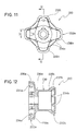
- Central hub 220 in accordance with a third embodiment of the present invention is illustrated.
- Central hub 220 is substantially identical to central hub 20 of the first embodiment except for portions now described. Therefore, central hub 220 will not be discussed or illustrated in detail herein.
- Central hub 220 is designed to use spoke nipples 28 for attaching spokes 22 and rim 24 thereto.
- central hub 220 has a tubular body portion 230, a left tubular mounting portion 232a and a right tubular mounting portion 232b.
- Left tubular mounting portion 232a is formed of a plurality of spoke attachment projections 238a and a tapered portion 239a.
- Left tubular mounting portion 232a is substantially identical to left tubular mounting portion 32a of the first embodiment.
- Tapered portion 239a fixedly couples left tubular mounting portion 232a to tubular body portion 230.
- Spoke attachment projections 238a are provided with a plurality of spoke attachment openings 234a formed therein. Spoke attachment openings 234a are substantially identical to spoke attachment openings 34a of the first embodiment.
- Right tubular portion 232b is different from right tubular mounting portion 32b of the first embodiment.
- right tubular mounting portions 232b has a cylindrical portion 237b and a tapered portion 239b. Tapered portion 239b fixedly couples cylindrical portion 237b to tubular body portion 230.
- Cylindrical portion 237b is provided with a plurality of spoke attachment openings 234b formed therein. Spoke attachment openings 234b are different from spoke attachment openings 34b of the first embodiment and spoke attachment openings 234a of left tubular mounting portion 232a.
- spoke attachment openings 234b are formed as longitudinal slots to allow spoke nipples to slide transversely into spoke attachment openings 234b formed in cylindrical portion 237b. Spoke attachment openings 234b are similar to spoke attachment openings 134a and 134b of the second embodiment.
- right tubular mounting portion 232b has a smaller maximum diameter than left tubular mounting portion 232a.
- spoke attachment openings 234b formed in cylindrical portion 237b are configured to use spoke nipples 28 for attaching spokes 22 and rim 24 thereto.
- the axial space D from a center point of one spoke attachment opening 234a to an adjacent center point of an adjacent spoke attachment opening 234a formed in a portion of hub 220 is less than about 20 millimeters.
- space D is about 16 millimeters. Therefore, when spoke nipples are inserted in spoke attachment openings 234a, a limited space of less than about 14 millimeters is provided between center points of a pair of head portions of adjacent spoke nipples arranged in one attachment projection 238a.
- Longitudinal slot shaped spoke attachment openings 234b make it possible to slide spoke nipples therein from a side of hub 220. This type of insertion can be easier than the first embodiment because of limited space within cylindrical portion 237b.
Landscapes
- Engineering & Computer Science (AREA)
- Mechanical Engineering (AREA)
- Tires In General (AREA)
- Connection Of Plates (AREA)
Applications Claiming Priority (2)
| Application Number | Priority Date | Filing Date | Title |
|---|---|---|---|
| US09/495,941 US6409278B1 (en) | 2000-02-02 | 2000-02-02 | Spoke nipple for bicycle wheel |
| US495941 | 2000-02-02 |
Publications (2)
| Publication Number | Publication Date |
|---|---|
| EP1122091A2 true EP1122091A2 (fr) | 2001-08-08 |
| EP1122091A3 EP1122091A3 (fr) | 2006-05-17 |
Family
ID=23970581
Family Applications (1)
| Application Number | Title | Priority Date | Filing Date |
|---|---|---|---|
| EP01101382A Withdrawn EP1122091A3 (fr) | 2000-02-02 | 2001-01-22 | Ecrou pour rayons de roue de bicyclette |
Country Status (5)
| Country | Link |
|---|---|
| US (1) | US6409278B1 (fr) |
| EP (1) | EP1122091A3 (fr) |
| JP (1) | JP3534705B2 (fr) |
| CN (1) | CN1236936C (fr) |
| TW (1) | TW524209U (fr) |
Cited By (9)
| Publication number | Priority date | Publication date | Assignee | Title |
|---|---|---|---|---|
| EP1310383A3 (fr) * | 2001-11-08 | 2005-03-30 | Trek Bicycle Corp. | Roue de bicyclette à rayons en paires avec jante optimisée extrudée et espacement de rayons et composants |
| WO2007075735A3 (fr) * | 2005-12-22 | 2007-10-18 | Specialized Bicycle Components | Roue et moyeu de bicyclette |
| EP1923231A1 (fr) * | 2006-11-20 | 2008-05-21 | CAMPAGNOLO S.r.l. | Roue, rayon et moyeu de bicyclette pour une telle roue et procédé d'assemblage de la roue |
| EP1923232A1 (fr) * | 2006-11-20 | 2008-05-21 | CAMPAGNOLO S.r.l. | Moyeu pour une roue de bicyclette et roue de bicyclette comprenant un tel moyeu |
| US7552935B2 (en) | 2005-09-26 | 2009-06-30 | Specialized Bicycle Components, Inc. | Integrated bicycle shifting and suspension system |
| US7562940B2 (en) | 2005-12-22 | 2009-07-21 | Specialized Bicycle Components, Inc. | Bicycle wheel and hub |
| US7562942B2 (en) | 2005-12-22 | 2009-07-21 | Specialized Bicycle Components, Inc. | Bicycle wheel and release mechanism |
| US7874625B2 (en) | 2008-09-04 | 2011-01-25 | Trek Bicycle Corporation | Bicycle wheel assembly having dissimilar lateral spoke lacings |
| WO2013156692A1 (fr) * | 2012-04-20 | 2013-10-24 | Mdpw | Roue de type roue de velo a rayons et, moyeu permettant d'equiper ladite roue |
Families Citing this family (28)
| Publication number | Priority date | Publication date | Assignee | Title |
|---|---|---|---|---|
| US6846047B2 (en) | 2001-09-28 | 2005-01-25 | Rolf Dietrich | Tensioned spoked wheel assembly and spoke rim and nipple therefor |
| EP1169182B1 (fr) * | 1999-04-09 | 2003-07-16 | DT Swiss AG | Ecrou de rayon, notamment pour bicyclettes et similaires |
| EP1231047B1 (fr) * | 2001-02-13 | 2004-01-14 | Campagnolo Srl | Procédé pour la fabrication d'un moyeu de bicyclette, dispositif pour sa mise en oeuvre et moyeu ainsi obtenu |
| US6517169B1 (en) * | 2002-03-26 | 2003-02-11 | Mark Yu | Spoked wheel for a bicycle |
| US6666525B1 (en) * | 2002-06-17 | 2003-12-23 | David J. Schroepfer | Spoked wheel apparatus |
| EP1569809B1 (fr) * | 2002-12-13 | 2010-08-11 | ALPINA RAGGI S.p.A. | Rayon pour roues et procede de fabrication correspondant |
| TW200424074A (en) * | 2003-05-12 | 2004-11-16 | Alex Global Technology Inc | Spoke with tubular coupling end portions |
| US6886892B2 (en) * | 2003-08-01 | 2005-05-03 | Tien Hsin Industries Co., Ltd | Combination of bicycle spokes and rims |
| DE602004012703D1 (de) * | 2004-01-27 | 2008-05-08 | Campagnolo Srl | Befestigungssystem für Speichen in einem Fahrradrad |
| US20050194834A1 (en) * | 2004-03-03 | 2005-09-08 | Chun-Hsung Chen | Bicycle spoke fixture assembly |
| US7093910B2 (en) * | 2004-12-08 | 2006-08-22 | Eric Alan Hjertberg | Fastening device for connecting spokes to rims |
| FR2882689B1 (fr) * | 2005-03-04 | 2007-04-27 | Salomon Sa | Moyeu d'une roue de cycle a rayons en traction et roue de cycle a rayons equipee d'un tel moyeu |
| US7306292B2 (en) * | 2005-05-27 | 2007-12-11 | Shimano Inc. | Bicycle hub |
| DE102006040919A1 (de) * | 2006-08-31 | 2008-03-06 | Dt Swiss Ag | Nabe und Laufrad, insbesondere für Fahrräder |
| US7621601B2 (en) * | 2007-11-21 | 2009-11-24 | Tien Hsin Industries Co., Ltd. | Bicycle hub |
| TW201204574A (en) * | 2010-07-22 | 2012-02-01 | jing-shan Wang | Bicycle wheel rim |
| US9561685B2 (en) * | 2012-02-09 | 2017-02-07 | Shimano, Inc. | Force-distributing apparatus for a bicycle wheel spoke |
| US9421818B2 (en) | 2012-12-21 | 2016-08-23 | Shimano Inc. | Bicycle hub and bicycle wheel |
| CN104129227A (zh) * | 2014-07-20 | 2014-11-05 | 郭克亚 | 一种辐条式轮子的花鼓 |
| US9815322B2 (en) * | 2015-01-19 | 2017-11-14 | Shimano Inc. | Bicycle hub and bicycle wheel assembly |
| DE102015207520A1 (de) | 2015-04-23 | 2016-10-27 | Sram Deutschland Gmbh | Fahrradnabe |
| ITUA20161779A1 (it) * | 2016-03-17 | 2017-09-17 | Campagnolo Srl | Ruota di bicicletta e relativo procedimento di fabbricazione |
| JP2017178215A (ja) * | 2016-03-31 | 2017-10-05 | 本田技研工業株式会社 | チューブレススポークホイールの構造 |
| DE102016107752A1 (de) * | 2016-04-26 | 2017-10-26 | Dt Swiss Ag | Nabe und Laufrad |
| CN107471903A (zh) * | 2017-07-25 | 2017-12-15 | 厦门鸿基伟业复材科技有限公司 | 一种碳纤维辐条及其制造方法 |
| US11260691B2 (en) * | 2019-02-11 | 2022-03-01 | Two Point Zero Usa, Inc. | Interchangeable hub system for bicycle |
| US11571929B2 (en) * | 2020-06-17 | 2023-02-07 | Shimano Inc. | Wheel hub |
| US20230322018A1 (en) * | 2022-04-11 | 2023-10-12 | DNA Specialty | Self-sealing Automotive Spoke Wheel Nipple |
Family Cites Families (16)
| Publication number | Priority date | Publication date | Assignee | Title |
|---|---|---|---|---|
| US436993A (en) * | 1890-09-23 | Cycle-wheel | ||
| GB189404449A (en) * | 1894-03-02 | 1895-02-02 | Charles Kingston Welch | Improvements in Tension or Suspension Wheels. |
| GB399963A (en) * | 1932-08-22 | 1933-10-19 | India Rubber Gutta Percha Tele | Improvements in or relating to wire-spoked vehicle wheels |
| FR788516A (fr) * | 1935-04-08 | 1935-10-11 | Perfectionnement apporté dans l'établissement des roues ou poulies à rayonnage métallique | |
| US2937905A (en) | 1955-11-29 | 1960-05-24 | Altenburger Karl | Spoke connection for tubeless tire rim |
| DE3342608C2 (de) * | 1983-11-25 | 1986-04-10 | Bayerische Motoren Werke AG, 8000 München | Speichenrad, insbesondere für einen schlauchlosen Reifen |
| JPS60259501A (ja) * | 1984-06-06 | 1985-12-21 | Yamaha Motor Co Ltd | スポ−ク車輪 |
| JPS6181801A (ja) * | 1984-08-31 | 1986-04-25 | Honda Motor Co Ltd | 車輌用ワイヤスポ−ク・ホイ−ルの組立て方法 |
| DE4306592A1 (de) | 1993-03-03 | 1994-09-15 | Moritz Friebel | Drahtspeichen für Fahrradspeichenlaufräder, die aus Felge, Speichen und Nabe bestehen, die unter Vorspannung miteinander verbunden sind |
| DE4415505C2 (de) | 1994-05-03 | 1997-02-13 | Moritz Friebel | Gewindehülsen für die Befestigung direkt in den Nabenkörper einzuschraubender Drahtspeichen für Fahrradspeichenlaufräder |
| US5810453A (en) * | 1994-08-09 | 1998-09-22 | O'brien; Colin | Bicycle wheels having hub tightened spoke system |
| FR2739059B1 (fr) | 1995-09-22 | 1997-12-12 | Mavic Sa | Moyeu de roue notamment pour cycle |
| JP3069284B2 (ja) | 1996-01-26 | 2000-07-24 | 株式会社シマノ | 自転車用ハブ |
| BE1009937A6 (nl) * | 1996-01-31 | 1997-11-04 | Piminvest N V | Nippel voor een wielspaak. |
| DE19724327B4 (de) | 1997-06-10 | 2009-01-29 | Sram Deutschland Gmbh | Nabe für ein Speichenrad |
| US6126243A (en) * | 1998-12-29 | 2000-10-03 | Shimano, Inc. | Bicycle wheel |
-
2000
- 2000-02-02 US US09/495,941 patent/US6409278B1/en not_active Expired - Lifetime
- 2000-12-13 TW TW091216292U patent/TW524209U/zh not_active IP Right Cessation
- 2000-12-29 CN CN00131083.6A patent/CN1236936C/zh not_active Expired - Fee Related
-
2001
- 2001-01-22 EP EP01101382A patent/EP1122091A3/fr not_active Withdrawn
- 2001-01-31 JP JP2001023006A patent/JP3534705B2/ja not_active Expired - Fee Related
Non-Patent Citations (1)
| Title |
|---|
| None |
Cited By (11)
| Publication number | Priority date | Publication date | Assignee | Title |
|---|---|---|---|---|
| EP1310383A3 (fr) * | 2001-11-08 | 2005-03-30 | Trek Bicycle Corp. | Roue de bicyclette à rayons en paires avec jante optimisée extrudée et espacement de rayons et composants |
| US7552935B2 (en) | 2005-09-26 | 2009-06-30 | Specialized Bicycle Components, Inc. | Integrated bicycle shifting and suspension system |
| WO2007075735A3 (fr) * | 2005-12-22 | 2007-10-18 | Specialized Bicycle Components | Roue et moyeu de bicyclette |
| US7562940B2 (en) | 2005-12-22 | 2009-07-21 | Specialized Bicycle Components, Inc. | Bicycle wheel and hub |
| US7562942B2 (en) | 2005-12-22 | 2009-07-21 | Specialized Bicycle Components, Inc. | Bicycle wheel and release mechanism |
| EP1923231A1 (fr) * | 2006-11-20 | 2008-05-21 | CAMPAGNOLO S.r.l. | Roue, rayon et moyeu de bicyclette pour une telle roue et procédé d'assemblage de la roue |
| EP1923232A1 (fr) * | 2006-11-20 | 2008-05-21 | CAMPAGNOLO S.r.l. | Moyeu pour une roue de bicyclette et roue de bicyclette comprenant un tel moyeu |
| US7874625B2 (en) | 2008-09-04 | 2011-01-25 | Trek Bicycle Corporation | Bicycle wheel assembly having dissimilar lateral spoke lacings |
| WO2013156692A1 (fr) * | 2012-04-20 | 2013-10-24 | Mdpw | Roue de type roue de velo a rayons et, moyeu permettant d'equiper ladite roue |
| FR2989630A1 (fr) * | 2012-04-20 | 2013-10-25 | Michel Debien | Roues de velo a rendement eleve |
| US9393832B2 (en) | 2012-04-20 | 2016-07-19 | Mdpw | Wheel of the spoked bicycle wheel type, and hub with which said wheel can be fitted |
Also Published As
| Publication number | Publication date |
|---|---|
| JP2001213101A (ja) | 2001-08-07 |
| JP3534705B2 (ja) | 2004-06-07 |
| EP1122091A3 (fr) | 2006-05-17 |
| CN1312175A (zh) | 2001-09-12 |
| TW524209U (en) | 2003-03-11 |
| CN1236936C (zh) | 2006-01-18 |
| US6409278B1 (en) | 2002-06-25 |
Similar Documents
| Publication | Publication Date | Title |
|---|---|---|
| EP1122091A2 (fr) | Ecrou pour rayons de roue de bicyclette | |
| EP1016553B1 (fr) | Roue de bicyclette | |
| US6409282B1 (en) | Bicycle hub | |
| US7192098B2 (en) | Bicycle rim | |
| US6692086B2 (en) | Bicycle wheel | |
| US6196638B1 (en) | Bicycle wheel | |
| EP1134096B1 (fr) | Jante de véhicule avec indicateur d'usure | |
| EP1559582B1 (fr) | Système de fixation des rayons d'un roue de bicyclette | |
| US20090256414A1 (en) | Bicycle wheel securing structure | |
| US7306292B2 (en) | Bicycle hub | |
| US6736462B1 (en) | Bicycle rim | |
| EP1236586B1 (fr) | Jante de bicyclette | |
| EP1068964B1 (fr) | Roue de bicyclette avec jante renforcée | |
| US7360847B2 (en) | Bicycle hub | |
| US7374251B2 (en) | Connection of Spokes to hub and rim in bicycle wheel | |
| EP1068963B1 (fr) | Roue de bicyclette avec jante renforcée | |
| US6485108B1 (en) | Bicycle hub |
Legal Events
| Date | Code | Title | Description |
|---|---|---|---|
| PUAI | Public reference made under article 153(3) epc to a published international application that has entered the european phase |
Free format text: ORIGINAL CODE: 0009012 |
|
| AK | Designated contracting states |
Kind code of ref document: A2 Designated state(s): AT BE CH CY DE DK ES FI FR GB GR IE IT LI LU MC NL PT SE TR |
|
| AX | Request for extension of the european patent |
Free format text: AL;LT;LV;MK;RO;SI |
|
| RIC1 | Information provided on ipc code assigned before grant |
Ipc: 7B 60B 27/02 B Ipc: 7B 60B 1/04 B Ipc: 7B 60B 21/06 A |
|
| PUAL | Search report despatched |
Free format text: ORIGINAL CODE: 0009013 |
|
| AK | Designated contracting states |
Kind code of ref document: A3 Designated state(s): AT BE CH CY DE DK ES FI FR GB GR IE IT LI LU MC NL PT SE TR |
|
| AX | Request for extension of the european patent |
Extension state: AL LT LV MK RO SI |
|
| 17P | Request for examination filed |
Effective date: 20060622 |
|
| RAP1 | Party data changed (applicant data changed or rights of an application transferred) |
Owner name: SHIMANO INC. |
|
| 17Q | First examination report despatched |
Effective date: 20061013 |
|
| AKX | Designation fees paid |
Designated state(s): AT BE CH CY DE DK ES FI FR GB GR IE IT LI LU MC NL PT SE TR |
|
| STAA | Information on the status of an ep patent application or granted ep patent |
Free format text: STATUS: THE APPLICATION IS DEEMED TO BE WITHDRAWN |
|
| 18D | Application deemed to be withdrawn |
Effective date: 20070224 |