EP1122101A2 - Suspension de roue pour véhicules, en particulier pour remorques de véhicules utilitaires - Google Patents
Suspension de roue pour véhicules, en particulier pour remorques de véhicules utilitaires Download PDFInfo
- Publication number
- EP1122101A2 EP1122101A2 EP01101853A EP01101853A EP1122101A2 EP 1122101 A2 EP1122101 A2 EP 1122101A2 EP 01101853 A EP01101853 A EP 01101853A EP 01101853 A EP01101853 A EP 01101853A EP 1122101 A2 EP1122101 A2 EP 1122101A2
- Authority
- EP
- European Patent Office
- Prior art keywords
- axle
- wheel
- vehicle frame
- wheel suspension
- suspension according
- Prior art date
- Legal status (The legal status is an assumption and is not a legal conclusion. Google has not performed a legal analysis and makes no representation as to the accuracy of the status listed.)
- Withdrawn
Links
- 239000000725 suspension Substances 0.000 title claims abstract description 27
- 239000006096 absorbing agent Substances 0.000 claims description 4
- 230000035939 shock Effects 0.000 claims description 4
- 239000000969 carrier Substances 0.000 claims 1
- 230000006835 compression Effects 0.000 description 2
- 238000007906 compression Methods 0.000 description 2
- 238000006073 displacement reaction Methods 0.000 description 2
- 238000010276 construction Methods 0.000 description 1
- 230000007704 transition Effects 0.000 description 1
Images

Classifications
-
- B—PERFORMING OPERATIONS; TRANSPORTING
- B60—VEHICLES IN GENERAL
- B60G—VEHICLE SUSPENSION ARRANGEMENTS
- B60G3/00—Resilient suspensions for a single wheel
- B60G3/18—Resilient suspensions for a single wheel with two or more pivoted arms, e.g. parallelogram
- B60G3/20—Resilient suspensions for a single wheel with two or more pivoted arms, e.g. parallelogram all arms being rigid
-
- B—PERFORMING OPERATIONS; TRANSPORTING
- B60—VEHICLES IN GENERAL
- B60G—VEHICLE SUSPENSION ARRANGEMENTS
- B60G11/00—Resilient suspensions characterised by arrangement, location or kind of springs
- B60G11/26—Resilient suspensions characterised by arrangement, location or kind of springs having fluid springs only, e.g. hydropneumatic springs
- B60G11/28—Resilient suspensions characterised by arrangement, location or kind of springs having fluid springs only, e.g. hydropneumatic springs characterised by means specially adapted for attaching the spring to axle or sprung part of the vehicle
-
- B—PERFORMING OPERATIONS; TRANSPORTING
- B60—VEHICLES IN GENERAL
- B60G—VEHICLE SUSPENSION ARRANGEMENTS
- B60G2200/00—Indexing codes relating to suspension types
- B60G2200/10—Independent suspensions
- B60G2200/14—Independent suspensions with lateral arms
- B60G2200/144—Independent suspensions with lateral arms with two lateral arms forming a parallelogram
- B60G2200/1442—Independent suspensions with lateral arms with two lateral arms forming a parallelogram including longitudinal rods
-
- B—PERFORMING OPERATIONS; TRANSPORTING
- B60—VEHICLES IN GENERAL
- B60G—VEHICLE SUSPENSION ARRANGEMENTS
- B60G2200/00—Indexing codes relating to suspension types
- B60G2200/10—Independent suspensions
- B60G2200/18—Multilink suspensions, e.g. elastokinematic arrangements
- B60G2200/182—Multilink suspensions, e.g. elastokinematic arrangements with one longitudinal arm or rod and lateral rods
-
- B—PERFORMING OPERATIONS; TRANSPORTING
- B60—VEHICLES IN GENERAL
- B60G—VEHICLE SUSPENSION ARRANGEMENTS
- B60G2202/00—Indexing codes relating to the type of spring, damper or actuator
- B60G2202/10—Type of spring
- B60G2202/15—Fluid spring
- B60G2202/152—Pneumatic spring
- B60G2202/1524—Pneumatic spring with two air springs per wheel, arranged before and after the wheel axis
-
- B—PERFORMING OPERATIONS; TRANSPORTING
- B60—VEHICLES IN GENERAL
- B60G—VEHICLE SUSPENSION ARRANGEMENTS
- B60G2204/00—Indexing codes related to suspensions per se or to auxiliary parts
- B60G2204/10—Mounting of suspension elements
- B60G2204/14—Mounting of suspension arms
- B60G2204/148—Mounting of suspension arms on the unsprung part of the vehicle, e.g. wheel knuckle or rigid axle
-
- B—PERFORMING OPERATIONS; TRANSPORTING
- B60—VEHICLES IN GENERAL
- B60G—VEHICLE SUSPENSION ARRANGEMENTS
- B60G2204/00—Indexing codes related to suspensions per se or to auxiliary parts
- B60G2204/40—Auxiliary suspension parts; Adjustment of suspensions
- B60G2204/422—Links for mounting suspension elements
-
- B—PERFORMING OPERATIONS; TRANSPORTING
- B60—VEHICLES IN GENERAL
- B60G—VEHICLE SUSPENSION ARRANGEMENTS
- B60G2206/00—Indexing codes related to the manufacturing of suspensions: constructional features, the materials used, procedures or tools
- B60G2206/01—Constructional features of suspension elements, e.g. arms, dampers, springs
- B60G2206/50—Constructional features of wheel supports or knuckles, e.g. steering knuckles, spindle attachments
-
- B—PERFORMING OPERATIONS; TRANSPORTING
- B60—VEHICLES IN GENERAL
- B60G—VEHICLE SUSPENSION ARRANGEMENTS
- B60G2300/00—Indexing codes relating to the type of vehicle
- B60G2300/38—Low or lowerable bed vehicles
Definitions
- the invention relates to a wheel suspension for vehicles, in particular Commercial vehicle trailer, with one via at least one suspension, in particular at least one bellows, and several trailing arms and wishbones on one Vehicle frame mounted axle body, parts of the vehicle frame or handlebar supports on the outside of the wheels in a vertical direction until they are pulled down over the wheels.
- the usual commercial vehicle trailers that are well known in practice have two parallel, extending between the wheels in the direction of travel Longitudinal beams on the underside of which, for example, the individual axle beams are suspended over air bellows.
- the structure of the commercial vehicle trailer is on the top of the side members arranged.
- For setting the track and the Fall of the individual wheels are also inward to the vehicle frame pointing and mounted on this trailing and / or wishbone.
- the Axle bodies of these known wheel suspensions for commercial vehicle trailers are generally designed as a continuous rigid axle rods on their a wheel is supported at both ends.
- the invention has for its object to develop a wheel suspension of the type mentioned so that the space between the opposite wheels seen in the direction of travel is available as usable storage space.
- axle body is designed as an axle stub for mounting the wheel, which is fixed to an axle support which is supported on the vehicle frame, and that the wishbones are based on the one-sided mounting on the axle support over at least almost the width extend of the respective wheel and are articulated at their other end to the outer parts of the vehicle frame.
- the axle support is on arranged on the inside of the wheel and the wishbones are on the side pulled down part of the vehicle frame stored.
- This embodiment, at the axle carrier is arranged on the inside of the wheel, is particularly in the Assembly and disassembly of the wheels advantageous.
- the axle it is too possible to arrange the axle on the outside of the wheel, then the Cross member across the wheel width on an inner part of the Vehicle frame are stored.
- each axle carrier mounted on the vehicle frame via at least three wishbones at least two wishbones overlap the wheel width on one side and at least one Wishbone the wheel width on the opposite side of this wheel spreads.
- at least three wishbones ensures that the wheel does not start to flutter when transverse forces occur and tracking is granted.
- the track is adjusted by adjusting it at least one wishbone.
- Trailing arms lying vertically one above the other as far apart as possible are spaced on the axle support.
- the stub axle carrying the braking device and thus the wheel is in accordance with a first embodiment of the invention screwed to the axle support, so that for repair purposes the stub axle together with the braking device can easily be separated from the axle beam.
- the Axle stub is welded to the axle support.
- the invention proposes that for the rapid repayment of Vibrations between the axle beam and the vehicle frame at least a shock absorber is arranged.
- the invention proposes that the axle support as in Side view H-shaped, double-walled and over several cross struts stiffened hollow profile is formed.
- This training of the axle carrier is particularly well suited to those that occur during driving and braking Take up forces and on the trailing and wishbones on the Derive vehicle frame.
- the wheel suspension shown in Fig. 1 consists essentially of a Axle carrier 1, which in the illustrated embodiment has two air bellows 2 as suspension elements on the parts arranged above Vehicle frame 3 is mounted.
- the axle beam 1 is also via two trailing arms 4 and three wishbones 5 on the supporting vehicle frame 3 of the vehicle or on parts rigidly connected to the vehicle frame.
- the control arms 4 and 5 are used to track and camber one on the axle support 1 set and maintain the mounted wheel 6. For the better 1 the wheel 6 in the Normal position only indicated schematically.
- the axle support 1 is a double-walled hollow profile stiffened by cross struts educated.
- the axle support 1 is approximately in the shape of an H lying on the side, the bellows 2 on the top of the upper of the parallel legs 1a are arranged.
- the wheel 6 itself is over a stub axle 8 and one on the stub axle arranged braking device, not shown in the drawing, on the Axle beam 1 stored.
- the stub axle 8 inserted into the axle bracket 1 and welded to the axle bracket 1.
- the stub axle 8 is the stub axle 8 with the Bolted axle bracket 1.
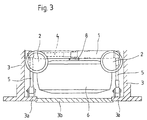
- the articulation of the trailing arms 4 and the wishbones 5 is shown in the figures Fig. 1 and 3.
- the two trailing arms 4 are vertically one above the other on one side articulated on one side of the axle support 1. With the other end they are Trailing arm 4 mounted on rigid parts of the vehicle frame 3.
- the axle beam 1 in the longitudinal direction i.e. guided in the direction of travel so that the axle beam 1 is always parallel to Frame construction is guided.
- the bearing points are located 4a of the trailing arm 4 on the axle beam 1 as far apart as possible to the To minimize trailing arms 4 forces occurring during driving, and when and rebound of the wheel 6 as little displacement of the wheel 6 in Longitudinal effect.
- the wishbones 5 are on the one hand Axle beam 1 and the other articulated to parts 3a, which are rigid with the Vehicle frames are connected.
- the extend Wishbone 5 proceeding from the axle support 1 in the direction of that on the axle support 1 fixed stub axle 8 so far that it at least the width of the wheel 6 partially overlap to a linkage on a part 3a of the vehicle frame 3 to allow it to run along the long sides of the vehicle in vertical Direction down to the wheel hub.
- This laterally outside the wheels lying frame parts 3a of the vehicle frame 3 are in the embodiment rigid vertical supports, the design and arrangement of Fig. 2 and the 3 can be seen.
- the wheels 6 are between the frame parts or supports 3a at least in Area of each wheel 6 segments 3b can be used in segments Can be part of the vehicle outer frame thus formed.
- the suspension described is advantageously characterized in that the use of the stub axle 8 instead of the usual continuous Axis body the space between each other in the direction of travel opposite wheels 6 is available as storage space.
- the wheels 6 the width across wishbones 5 also allow the full Use of the storage space between the wheels 6 from the rear of the vehicle.
Landscapes
- Engineering & Computer Science (AREA)
- Mechanical Engineering (AREA)
- Vehicle Body Suspensions (AREA)
Applications Claiming Priority (2)
| Application Number | Priority Date | Filing Date | Title |
|---|---|---|---|
| DE2000104227 DE10004227A1 (de) | 2000-02-01 | 2000-02-01 | Radaufhängung für Fahrzeuge, insbesondere Nutzfahrzeuganhänger |
| DE10004227 | 2000-02-01 |
Publications (2)
| Publication Number | Publication Date |
|---|---|
| EP1122101A2 true EP1122101A2 (fr) | 2001-08-08 |
| EP1122101A3 EP1122101A3 (fr) | 2003-11-19 |
Family
ID=7629373
Family Applications (1)
| Application Number | Title | Priority Date | Filing Date |
|---|---|---|---|
| EP01101853A Withdrawn EP1122101A3 (fr) | 2000-02-01 | 2001-01-26 | Suspension de roue pour véhicules, en particulier pour remorques de véhicules utilitaires |
Country Status (2)
| Country | Link |
|---|---|
| EP (1) | EP1122101A3 (fr) |
| DE (1) | DE10004227A1 (fr) |
Cited By (5)
| Publication number | Priority date | Publication date | Assignee | Title |
|---|---|---|---|---|
| WO2004076263A1 (fr) * | 2003-02-27 | 2004-09-10 | Tg Consulting, Besloten Vennootschap Met Beperkte Aansprakelijkheid | Chassis de semi-remorque et suspension de roues |
| EP1127749A3 (fr) * | 2000-02-24 | 2005-12-14 | SCHIMMELPFENNIG, Karl-Heinz | Cadre de protection pour véhicules routiers |
| FR2914586A1 (fr) * | 2007-04-03 | 2008-10-10 | Renault Sas | Train arriere multi-bras pour vehicule automobile |
| NL2013397B1 (nl) * | 2014-09-01 | 2016-09-26 | Broshuis B V | Onafhankelijke wielophanging met luchtvering voor een oplegger en opleggers daarmee uitgerust. |
| EP3978279A1 (fr) * | 2020-10-01 | 2022-04-06 | Onomotion GmbH | Wagon pour le transport de personnes et/ou de marchandises |
Family Cites Families (7)
| Publication number | Priority date | Publication date | Assignee | Title |
|---|---|---|---|---|
| US2330482A (en) * | 1941-03-26 | 1943-09-28 | Twin Coach Co | Vehicle spring suspension |
| US2466832A (en) * | 1946-04-20 | 1949-04-12 | Marmon Herrington Co Inc | Wheel suspension |
| US3511493A (en) * | 1967-10-23 | 1970-05-12 | Gen Motors Corp | Camber change and roll steer inducing leaf spring suspension |
| US4610461A (en) * | 1985-06-17 | 1986-09-09 | Matthew Guzzetta | Steering system for elimination of bump steering in independent wheel suspension systems |
| IT1255575B (it) * | 1992-07-10 | 1995-11-09 | Sospensione a minimo ingombro trasversale, in particolare per veicoli a pianale ribassato. | |
| DE4336672A1 (de) * | 1993-10-27 | 1995-05-04 | Zahnradfabrik Friedrichshafen | Einzelradaufhängung |
| DE19544276B4 (de) * | 1994-12-06 | 2005-11-24 | Volkswagen Ag | Einzelradaufhängung für die gelenkten Räder einer Kraftfahrzeug-Vorderachse |
-
2000
- 2000-02-01 DE DE2000104227 patent/DE10004227A1/de not_active Ceased
-
2001
- 2001-01-26 EP EP01101853A patent/EP1122101A3/fr not_active Withdrawn
Non-Patent Citations (1)
| Title |
|---|
| None |
Cited By (9)
| Publication number | Priority date | Publication date | Assignee | Title |
|---|---|---|---|---|
| EP1127749A3 (fr) * | 2000-02-24 | 2005-12-14 | SCHIMMELPFENNIG, Karl-Heinz | Cadre de protection pour véhicules routiers |
| WO2004076263A1 (fr) * | 2003-02-27 | 2004-09-10 | Tg Consulting, Besloten Vennootschap Met Beperkte Aansprakelijkheid | Chassis de semi-remorque et suspension de roues |
| BE1015391A3 (nl) * | 2003-02-27 | 2005-03-01 | Tg Consulting Bv Met Beperkte | Verbeterde oplegger. |
| CN100431899C (zh) * | 2003-02-27 | 2008-11-12 | Tg咨询有限责任公司 | 半拖车底盘及车轮悬架 |
| FR2914586A1 (fr) * | 2007-04-03 | 2008-10-10 | Renault Sas | Train arriere multi-bras pour vehicule automobile |
| WO2008129211A1 (fr) * | 2007-04-03 | 2008-10-30 | Renault S.A.S | Train arriere multi-bras pour vehicule automobile |
| NL2013397B1 (nl) * | 2014-09-01 | 2016-09-26 | Broshuis B V | Onafhankelijke wielophanging met luchtvering voor een oplegger en opleggers daarmee uitgerust. |
| EP3978279A1 (fr) * | 2020-10-01 | 2022-04-06 | Onomotion GmbH | Wagon pour le transport de personnes et/ou de marchandises |
| US11541709B2 (en) | 2020-10-01 | 2023-01-03 | Onomotion Gmbh | Vehicle for the transport of persons and/or goods |
Also Published As
| Publication number | Publication date |
|---|---|
| EP1122101A3 (fr) | 2003-11-19 |
| DE10004227A1 (de) | 2001-08-02 |
Similar Documents
| Publication | Publication Date | Title |
|---|---|---|
| DE1605826C3 (de) | Drehgestell für Eisenbahnwagen mit mindestens zwei Radsätzen | |
| EP0290587B1 (fr) | Suspension indépendante pour un véhicule, particulièrement pour un autobus | |
| EP1404536A1 (fr) | Essieu arriere d'un vehicule automobile dote de cinq bras oscillants | |
| DE1630839B2 (de) | Achsaufhaengung fuer kraftfahrzeuge | |
| EP2435263B1 (fr) | Suspension de roue individuelle pour véhicule | |
| EP0352541A1 (fr) | Suspension élastique d'essieu pour véhicules automobiles, notamment pour véhicules utilitaires | |
| DE1086138B (de) | Einzelradaufhaengung fuer Lastwagen | |
| DE19622954C2 (de) | Radaufhängung für ein Kraftfahrzeug | |
| DE19533263A1 (de) | Drehgestell für Schienenfahrzeuge | |
| DE19756066C2 (de) | Fahrzeugachse mit mindestens einem, mindestens einen Hebel aufweisenden, radtragenden Lenker pro Fahrzeugrad | |
| EP1122101A2 (fr) | Suspension de roue pour véhicules, en particulier pour remorques de véhicules utilitaires | |
| DE3139805A1 (de) | Einzelradaufhaengung fuer fahrzeuge, insbesondere kraftfahrzeuge | |
| DE10011417B4 (de) | Einzelradaufhängung mit radführenden Schräglenkern | |
| DE2439365B2 (de) | Radaufhängung für Kraftfahrzeuge, insbesondere für Personenkraftwagen | |
| DE69304236T2 (de) | Radaufhängungsvorrichtung für einen lenkbaren Vorderradsatz eines Nutzfahrzeuges | |
| DE3338467A1 (de) | Hinterradaufhaengung | |
| DE4309324C1 (de) | Einachsfahrwerk für Schienenfahrzeuge | |
| DE2932685C2 (de) | Achsanlenkung für eine angetriebene Achse eines Omnibusses | |
| EP1277603A2 (fr) | Suspension de roue indépendante multibras, en particulier suspension d'une roue avant directrice pour véhicule automobile | |
| DE2415708A1 (de) | Starrachse, vorzugsweise hinterradachse, fuer kraftfahrzeuge | |
| DE3124837C2 (de) | Transportfahrzeug, insbesondere Anhängerfahrzeug | |
| DE4407398C2 (de) | Achslift für luftgefederte Fahrzeugachsen | |
| EP0225851B1 (fr) | Dispositif de suspension de roue pour un véhicule tous terrains à progression lente, en particulier pour voiture à traction par cheval | |
| DE900059C (de) | Federung fuer Fahrzeuge | |
| DE2629518A1 (de) | Einzelradaufhaengung fuer fahrzeuge |
Legal Events
| Date | Code | Title | Description |
|---|---|---|---|
| PUAI | Public reference made under article 153(3) epc to a published international application that has entered the european phase |
Free format text: ORIGINAL CODE: 0009012 |
|
| AK | Designated contracting states |
Kind code of ref document: A2 Designated state(s): AT BE CH CY DE DK ES FI FR GB GR IE IT LI LU MC NL PT SE TR |
|
| AX | Request for extension of the european patent |
Free format text: AL;LT;LV;MK;RO;SI |
|
| PUAL | Search report despatched |
Free format text: ORIGINAL CODE: 0009013 |
|
| AK | Designated contracting states |
Kind code of ref document: A3 Designated state(s): AT BE CH CY DE DK ES FI FR GB GR IE IT LI LU MC NL PT SE TR |
|
| AX | Request for extension of the european patent |
Extension state: AL LT LV MK RO SI |
|
| RIC1 | Information provided on ipc code assigned before grant |
Ipc: 7B 60B 35/02 B Ipc: 7B 62D 17/00 B Ipc: 7B 60G 3/20 B Ipc: 7B 60G 11/28 A |
|
| AKX | Designation fees paid | ||
| REG | Reference to a national code |
Ref country code: DE Ref legal event code: 8566 |
|
| STAA | Information on the status of an ep patent application or granted ep patent |
Free format text: STATUS: THE APPLICATION IS DEEMED TO BE WITHDRAWN |
|
| 18D | Application deemed to be withdrawn |
Effective date: 20040521 |