EP1122154A2 - Element de structure renforcé avec mousse expansible à chaud nervurée - Google Patents
Element de structure renforcé avec mousse expansible à chaud nervurée Download PDFInfo
- Publication number
- EP1122154A2 EP1122154A2 EP01101686A EP01101686A EP1122154A2 EP 1122154 A2 EP1122154 A2 EP 1122154A2 EP 01101686 A EP01101686 A EP 01101686A EP 01101686 A EP01101686 A EP 01101686A EP 1122154 A2 EP1122154 A2 EP 1122154A2
- Authority
- EP
- European Patent Office
- Prior art keywords
- reinforcing material
- reinforcing
- carrier
- ribs
- structural member
- Prior art date
- Legal status (The legal status is an assumption and is not a legal conclusion. Google has not performed a legal analysis and makes no representation as to the accuracy of the status listed.)
- Withdrawn
Links
- 230000003014 reinforcing effect Effects 0.000 title claims abstract description 53
- 238000005187 foaming Methods 0.000 title abstract description 14
- 239000000463 material Substances 0.000 title description 44
- 239000012779 reinforcing material Substances 0.000 claims abstract description 59
- IISBACLAFKSPIT-UHFFFAOYSA-N bisphenol A Chemical compound C=1C=C(O)C=CC=1C(C)(C)C1=CC=C(O)C=C1 IISBACLAFKSPIT-UHFFFAOYSA-N 0.000 claims description 10
- 239000003981 vehicle Substances 0.000 claims description 10
- 229920001971 elastomer Polymers 0.000 claims description 7
- 230000005484 gravity Effects 0.000 claims description 7
- 230000002787 reinforcement Effects 0.000 claims description 7
- 239000004793 Polystyrene Substances 0.000 claims description 6
- VYPSYNLAJGMNEJ-UHFFFAOYSA-N Silicium dioxide Chemical compound O=[Si]=O VYPSYNLAJGMNEJ-UHFFFAOYSA-N 0.000 claims description 6
- 229920001400 block copolymer Polymers 0.000 claims description 6
- 229920002223 polystyrene Polymers 0.000 claims description 6
- 239000011521 glass Substances 0.000 claims description 5
- 239000004005 microsphere Substances 0.000 claims description 5
- 239000006229 carbon black Substances 0.000 claims description 4
- 239000004850 liquid epoxy resins (LERs) Substances 0.000 claims description 4
- 239000004604 Blowing Agent Substances 0.000 claims description 3
- 239000003054 catalyst Substances 0.000 claims description 3
- 239000003795 chemical substances by application Substances 0.000 claims description 3
- 239000000377 silicon dioxide Substances 0.000 claims description 3
- 239000000203 mixture Substances 0.000 abstract description 16
- 230000004913 activation Effects 0.000 abstract description 5
- 238000004519 manufacturing process Methods 0.000 abstract description 5
- 230000001788 irregular Effects 0.000 abstract description 4
- 239000011347 resin Substances 0.000 abstract description 3
- 229920005989 resin Polymers 0.000 abstract description 3
- 239000003973 paint Substances 0.000 abstract description 2
- 239000000843 powder Substances 0.000 abstract description 2
- FACXGONDLDSNOE-UHFFFAOYSA-N buta-1,3-diene;styrene Chemical compound C=CC=C.C=CC1=CC=CC=C1.C=CC1=CC=CC=C1 FACXGONDLDSNOE-UHFFFAOYSA-N 0.000 description 6
- 238000010438 heat treatment Methods 0.000 description 6
- 229920000468 styrene butadiene styrene block copolymer Polymers 0.000 description 6
- 238000001994 activation Methods 0.000 description 5
- XOZUGNYVDXMRKW-AATRIKPKSA-N azodicarbonamide Chemical compound NC(=O)\N=N\C(N)=O XOZUGNYVDXMRKW-AATRIKPKSA-N 0.000 description 5
- 229920000459 Nitrile rubber Polymers 0.000 description 4
- XLOMVQKBTHCTTD-UHFFFAOYSA-N Zinc monoxide Chemical compound [Zn]=O XLOMVQKBTHCTTD-UHFFFAOYSA-N 0.000 description 4
- 239000006260 foam Substances 0.000 description 4
- 239000002184 metal Substances 0.000 description 4
- 229910052751 metal Inorganic materials 0.000 description 4
- NTXGQCSETZTARF-UHFFFAOYSA-N buta-1,3-diene;prop-2-enenitrile Chemical compound C=CC=C.C=CC#N NTXGQCSETZTARF-UHFFFAOYSA-N 0.000 description 3
- QGBSISYHAICWAH-UHFFFAOYSA-N dicyandiamide Chemical compound NC(N)=NC#N QGBSISYHAICWAH-UHFFFAOYSA-N 0.000 description 3
- XXOYNJXVWVNOOJ-UHFFFAOYSA-N fenuron Chemical compound CN(C)C(=O)NC1=CC=CC=C1 XXOYNJXVWVNOOJ-UHFFFAOYSA-N 0.000 description 3
- 238000002844 melting Methods 0.000 description 3
- 230000008018 melting Effects 0.000 description 3
- 238000000034 method Methods 0.000 description 3
- 239000004156 Azodicarbonamide Substances 0.000 description 2
- 229910000831 Steel Inorganic materials 0.000 description 2
- 235000019399 azodicarbonamide Nutrition 0.000 description 2
- 238000013461 design Methods 0.000 description 2
- LRCFXGAMWKDGLA-UHFFFAOYSA-N dioxosilane;hydrate Chemical compound O.O=[Si]=O LRCFXGAMWKDGLA-UHFFFAOYSA-N 0.000 description 2
- 239000003822 epoxy resin Substances 0.000 description 2
- 239000008240 homogeneous mixture Substances 0.000 description 2
- 238000003780 insertion Methods 0.000 description 2
- 230000037431 insertion Effects 0.000 description 2
- 239000008188 pellet Substances 0.000 description 2
- 229920000647 polyepoxide Polymers 0.000 description 2
- 239000010959 steel Substances 0.000 description 2
- XLYOFNOQVPJJNP-UHFFFAOYSA-N water Substances O XLYOFNOQVPJJNP-UHFFFAOYSA-N 0.000 description 2
- 239000011787 zinc oxide Substances 0.000 description 2
- KUBDPQJOLOUJRM-UHFFFAOYSA-N 2-(chloromethyl)oxirane;4-[2-(4-hydroxyphenyl)propan-2-yl]phenol Chemical compound ClCC1CO1.C=1C=C(O)C=CC=1C(C)(C)C1=CC=C(O)C=C1 KUBDPQJOLOUJRM-UHFFFAOYSA-N 0.000 description 1
- -1 Celogen AZ 765® Chemical compound 0.000 description 1
- 239000004677 Nylon Substances 0.000 description 1
- 230000003213 activating effect Effects 0.000 description 1
- 239000000853 adhesive Substances 0.000 description 1
- 230000001070 adhesive effect Effects 0.000 description 1
- 238000007664 blowing Methods 0.000 description 1
- 230000006835 compression Effects 0.000 description 1
- 238000007906 compression Methods 0.000 description 1
- 238000010276 construction Methods 0.000 description 1
- 230000002950 deficient Effects 0.000 description 1
- 238000011161 development Methods 0.000 description 1
- 239000004615 ingredient Substances 0.000 description 1
- 238000002347 injection Methods 0.000 description 1
- 239000007924 injection Substances 0.000 description 1
- 238000001746 injection moulding Methods 0.000 description 1
- 238000009434 installation Methods 0.000 description 1
- 229920001778 nylon Polymers 0.000 description 1
- 238000004806 packaging method and process Methods 0.000 description 1
- 230000037361 pathway Effects 0.000 description 1
- 239000000049 pigment Substances 0.000 description 1
- 239000004033 plastic Substances 0.000 description 1
- 238000012545 processing Methods 0.000 description 1
- 238000007789 sealing Methods 0.000 description 1
- 230000000087 stabilizing effect Effects 0.000 description 1
- 238000006467 substitution reaction Methods 0.000 description 1
- 238000007725 thermal activation Methods 0.000 description 1
- 238000009827 uniform distribution Methods 0.000 description 1
Images


Classifications
-
- B—PERFORMING OPERATIONS; TRANSPORTING
- B62—LAND VEHICLES FOR TRAVELLING OTHERWISE THAN ON RAILS
- B62D—MOTOR VEHICLES; TRAILERS
- B62D29/00—Superstructures, understructures, or sub-units thereof, characterised by the material thereof
- B62D29/001—Superstructures, understructures, or sub-units thereof, characterised by the material thereof characterised by combining metal and synthetic material
- B62D29/002—Superstructures, understructures, or sub-units thereof, characterised by the material thereof characterised by combining metal and synthetic material a foamable synthetic material or metal being added in situ
Definitions
- This present invention relates generally to thermally expansible, foaming, structural reinforcing members used to provide localized stiffness to frames, rails, cavities, panels, and other structural members such as those found in automotive, aviation, or marine applications.
- the inventive reinforcing members include a thermally expansible, foaming reinforcing material that is secured to a carrier or support which maintains the reinforcing member in the desired orientation within the cavity, frame, or rail of the structural member until the material is thermally expanded.
- the reinforcing material comprises a plurality of spaced-part ribs or fins which permit heated air to contact a greater surface area of the material so as to improve volumetric expansion performance thereof
- U.S. Patent No. 5,213,391 to Takagi discloses a body skeleton structure for a vehicle comprising an inner panel (3) of a front pillar (1) with which a bracket section (16) is integrally formed (see Figs. 5-7).
- the bracket section (16) extends towards an inner surface of an outer panel (2) and includes flanges (17) having thermally foaming rubber sheet (18a) adhered to its outer surfaces. Rubber sheet (18a) expands upon heating in order to minimize gaps around the bracket section (16).
- the Takagi structure is deficient in that a bracket section (16) must be integrally formed with pillar (1).
- bracket (16) must have an overall shape which corresponds to that of the cross-sectional shape of pillar (1) and an overall size which is only slightly less than the cross-sectional size of pillar (1) in order to minimize the likelihood of gaps within the pillar. This requires substantial work on the part of the vehicle manufacturer, thus leading to increased costs.
- U.S. Patent No. 5,755,486 to Wycech is directed towards a w-shaped reinforcement member that carries a thermally expansible resin-based material (see Figs. 1-4).
- the w-shaped reinforcement member is placed in the channel of a hollow structural member over a transverse pin which fits through the slot of the w-shaped member and maintains it in position until such time as the material is heat-expanded.
- the Wycech reinforcement member is lacking in that it does not properly reinforce narrow or irregular-shaped cavities, thus limiting its applications in motor vehicles.
- the instant invention overcomes these problems by providing a thermally expansible, foaming, reinforcing member for reinforcing a hollow structural member (such as one in an automobile rail) at a pre-determined location within the cavity.
- the reinforcing member includes a portion formed of a thermally expansible, foaming, reinforcing material.
- the reinforcing material is preferably a synthetic, resin-based material which expands when subjected to temperatures achieved at specific points in a manufacturing process (e.g., such as during the paint or powder bake stages of automobile manufacturing processes). This expansion is achieved either by internally created thermal energy or by the external application of heat to activate the material.
- thermally expansible means both internally created thermal energy and the external application of heat to expand and foam the reinforcing material.
- the expansion temperature of the material should be at least about 300°F.
- the expansible material of the inventive reinforcing member comprises at least two spaced-apart ribs (and preferably three or more ribs).
- the thickness of the ribs and the distance between these ribs should be such that, upon heat activation, the ribs will expand outward in all directions, contacting and "melding" with any adjacent ribs to form a substantially uniformly dense, expanded reinforcing material.
- the distance between the ribs can be varied, but preferably ranges from about 0.5-1.5 cm.
- the shortest distance between a pair of ribs should be at least about 0.1 cm, and preferably at least about 0.5 cm, while the longest distance between a pair of ribs can be varied but is preferably less than about 1.5 cm. These distances are important in order to allow sufficient heated air to contact all of the rib surfaces while maintaining the ribs sufficiently close to allow the expanded ribs to contact one another and form a uniform, expanded block of the material.
- the ribs are preferably integral with a base portion formed ofthe same thermally expansible material.
- the inventive reinforcing member further comprises a carrier to which the expansible material is secured.
- the carrier is useful for maintaining the expansible material in the desired location and orientation within the cavity until thermal expansion is effected.
- the carrier should be formed of a material having a melting point higher than the expansion or foaming temperature of the expansible material (e.g., metal or nylon). Furthermore, the melting point of the carrier should be higher than any processing temperatures to which the intended structural member will be subjected.
- the carrier can be sized and shaped as necessary to support the reinforcing member, while the expansible material is generally sized and shaped to correspond to the cross-sectional shape of the cavity in which the reinforcing member will be utilized. Furthermore, the size and shape of the carrier can be designed so as to assist in directing the flow of the thermally expanding material into small and/or irregular shaped crevices while simultaneously restricting the flow of the material to other locations in the cavity.
- Figs. 1-4 illustrate a preferred ribbed reinforcing member according to the invention.
- the reinforcing member 10 includes a thermally expansible foaming material 12 and a carrier 14.
- Expansible, reinforcing material 12 is formed of a plurality of angularly oriented fins or ribs 16a-g having respective upper ends 18a-g and respective lower ends 20a-g.
- Ribs 16a-g are each preferably integrally connected with a base 21 having a forward margin 23 so that each pair of ribs 16a-g forms a valley 22a-f therebetween, with each of the valleys 22a-f being formed in part by a bottom surface 24a-f which is a surface shared by the base 21.
- Ribs 16a, 16c, and 16d further include threaded openings 26, shown in phantom.
- each of ribs 16a-g is free-standing (i.e., the ribs do not include any type of carrier or retaining means on their respective surfaces) and includes a generally flush, forward surface 28a-g, a generally flush, rearward surface 30a-g, and a generally horizontal, upper surface 32a-g.
- Surfaces 30c-g and 28a-e are essentially parallel to forward margin 23 of base 21 while surfaces 30a,b and 28f,g are essentially perpendicular to forward margin 23 of base 21.
- Each of ribs 16a-g include respective leftward outer surfaces 34a-g and rightward outer surfaces 36a-g. Referring to Figs 1, 2, and 4, it can be seen that each of ribs 16a-g is wider at its respective lower end 20a-g. As a result, each of valleys 22a-f become narrower towards their respective bottom surfaces 24a-f
- the composition 38 used in the present invention is a dry, initially non-tacky material that develops adhesion upon expansion so that it adheres to the surrounding structural members when activated. Activation may be by heating, such as occurs in automobile assembly plants.
- the thermally expansible foaming material should have a percent expansion of at least about 40%, preferably at least about 125%, and more preferably from about 150-300%, to provide sufficient structural reinforcement and compressive strength.
- the percent expansion is defined as: 100 x ⁇ [(the specific gravity of the material 12 before heating) - (the specific gravity of the material 12 after heating)]/(the specific gravity of the material 12 after heating) ⁇ .
- composition 38 for use as reinforcing material 12 is commercialized under the name SikaReinforcer (Sika Corporation, Madison Heights, Michigan).
- the most preferred composition 38 comprises: from about 20-30% by weight of a styrene-butadiene-styrene (SBS) block co-polymer (e.g., Fina Clear 530® ); from about 5-20% by weight of a polystyrene (e.g., Fina Crystal 500® and Fina Crystal 535® ); from about 30-45% by weight of a bisphenol A-based liquid epoxy resin (e.g.
- SBS styrene-butadiene-styrene
- Araldite 6010® and Epon 71® from about 0.5-5% by weight of a pigment such as carbon black; up to about 5% by weight butadiene acrylonitrile rubber (Nipol 1411); from about 1-10% by weight hydrated amorphous silica (HiSil 233); from about 10-20% by weight glass microspheres (Scotchlite S60); from about 0.1-5% by weight of a blowing agent such as azodicarbonamide (e.g., Celogen AZ 765® , Celogen AZ 754A® , and Celogen AZ 130® ); from about 0.1-5% by weight of a catalyst such as N, N, dimethyl phenyl urea (U405); from about 0.1-5% by weight of a curing agent such as dicyandiamide (DDA10); and up to about 5% by weight of a "kicker" such as zinc oxide to lower the blowing temperature, with all percents by weight being based upon the total weight of the composition taken
- a particularly preferred composition 38 for use as material 38 comprises about 12.94% by weight polystyrene, about 23.22% by weight SBS block copolymer, about 0.57% by weight carbon black, about 1.90% by weight butadiene acrylonitrile rubber, about 4.28% by weight hydrated amorphous silica, about 38.07% by weight bisphenol A-based liquid epoxy resin, about 14.75% by weight glass microspheres, about 0.46% by weight zinc oxide, about 2.85% by weight dicyandiamide, about 0.38% by weight N,N dimethyl phenyl urea, and about 0.57% by weight azodicarbonamide.
- the foregoing may be adjusted such that the polystyrene is reduced to about 12.63% by weight, the SBS block copolymer is reduced to about 22.59% by weight, and the butadiene acrylonitrile rubber is increased to about 2.85% by weight.
- the composition 38 can be formed by mixing the SBS block co-polymer with a small portion (about 1/40th of the total amount) of the bisphenol A-based liquid epoxy resin in a heated mixer until the temperature ofthe mixer reaches from about 240-260°F (the temperature of the mixture within the mixer is at least about 175°F), and the mixture is substantially homogeneous, at which time the polystyrene is added to the mixer and mixing is continued. After the polystyrene is substantially mixed with the SBS block co-polymer/epoxy resin mixture, the remainder of the bisphenol A-based epoxy resin is slowly added to the mixer, stopping and starting the mixer as necessary, with the ingredients being thoroughly mixed to obtain a substantially homogeneous mixture.
- the desired amount of this mixture is placed in a heated mixer (set at a temperature of about 250°F) and mixing is commenced. While mixing, the carbon black and rubber are added to the mixer and mixing is stopped once a homogeneous mixture is obtained within the mixer. Either the silica or glass microspheres is added to the mixer, and mixing is resumed and continued until the mixture is homogeneous. This step is repeated, adding the other of the silica or glass microspheres.
- the temperature of the mixer is then set to a temperature below 160°F, the blowing agent(s), catalyst(s), kicker, and curing agent(s) are added, and mixing is resumed and continued only until the mixture is homogeneous.
- the resulting mixture is then preferably extruded into strands (at an extruder temperature of 170-180°F and screw rotation speeds of about 400 rpm) and cut into pellets.
- the resulting pellets are injection molded at a temperature of about 180-200 °F using injection molding equipment designed to form the desired shape of the reinforcing material 12 to be attached to the carrier 14.
- the carrier 14 comprises a flat plate 40 and upper and lower vertical plates 42, 44, respectively.
- plates 42, 44 are essentially perpendicular to plate 40.
- Plate 40 and plate 44 are joined at bend 46, with plates 42, 44 being essentially parallel to one another.
- Reinforcing material 12 is secured to carrier 14 by way of push-pins 48 which are inserted through holes 47 in plate 40 and into openings 26.
- the overall width of reinforcing material 12 is slightly greater than the width of plate 40, creating an "overhang" area 49.
- the carrier 14 is formed of a material having a melting point that is higher than both the activation (i.e., foaming) temperature of the composition 38 of which reinforcing material 12 is formed and the temperature to which any structural member containing the reinforcing member 10 would be exposed.
- carrier 14 is formed of steel.
- the size and shape of the carrier 14 is not critical, so long as carrier 14 is capable of fitting within the cavity of the particular structural member in which it is to be utilized. Furthermore, the flow of the reinforcing material 12 should be sufficiently directed by the carrier 14 during expansion so that the expanded material contacts and adheres to the cavity walls and substantially fills any crevices.
- the reinforcing member 10 is preferably provided to a manufacturer preassembled (i.e., with the non-expanded material 12 attached to carrier 14) for insertion into the cavity of the desired structural member, such as during construction of an automobile.
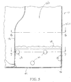
- Figs. 5-7 illustrate the positioning of reinforcing member 10 in an automobile structural member.
- a box-shaped structural member 50 is formed of steel and comprises four sidewalls 52a-d which cooperate with an endwall 54 to form a box-shaped cavity 56.
- Reinforcing member 10 is inserted into structural member 50 in such a manner that the overall configuration of reinforcing material 12 corresponds to the rectangular cross-section of cavity 56. That is, reinforcing member 10 is inserted into cavity 56 so that the flat upper surfaces 32a-g of ribs 16a-g are substantially in contact with the surface of wall 52b, while the rearward surfaces 30c-g are in contact with endwall 54. Finally, surfaces 30a,b are positioned adjacent wall 52c. Lower vertical plate 44 is positioned adjacent wall 52a upon insertion of reinforcing member 10 into cavity 56.
- Plate 44 is then fastened to wall 52a via welds or rivets 58, thus stabilizing reinforcing member 10 within the cavity 56 until such time as the structural member 50 is exposed to an elevated temperature sufficient to activate the reinforcing material 12, causing it to foam.
- structural member 50 is a component of a vehicle
- any of a number of process or manufacturing steps may be carried out on the vehicle body prior to thermal expansion without affecting the ability ofthe reinforcing material 12 to expand when exposed to the actual activating temperature.
- the reinforcing material 12 begins to expand in all directions. That is, the reinforcing material 12 expands towards the cavity walls 52a-d and 54 forming expanded material 60. To a limited degree, reinforcing material 12 expands beyond upper vertical plate 42 at location 62 (see Fig. 7). Furthermore, reinforcing material 12 expands somewhat beyond flat plate 40, however, flat plate 40 serves to restrict the material from flowing in a direction away from wall 52d thus directing the expanding material against the cavity walls 52a-c and 54 and into the corners of the cavity 56 (see Figs. 6-7). Advantageously, this results in a dense and uniform distribution of expanded material 60 within this rather tight area of the structural member 50.
- thermally reinforcing material 12 is secured to carrier 14 via bend tabs 64a,b.
- bend tabs 64a,b is formed by removing a strip of metal from flat plate 40 to create openings 66a,b. These metal strips are then passed through openings (not shown) in base 21 of reinforcing material 12 between ribs 16a,b and 16d,e. The metal strips are bent away from the respective plate openings 66a,b, and against surfaces 24a,d, to form an "L" configuration having respective upper legs 68a,b and respective lower legs 70a,b.
- Figs. 9-10 illustrate reinforcing material 12 after thermal expansion to form material 60.
- the ribs 16a-g expand outwardly in all directions thus covering tabs 64a,b.
- base 21 expands somewhat through openings 66a,b as shown in Fig. 9.
- the ribbed design of reinforcing material 12 in both embodiments allows for improved expansion of the reinforcing material 12. That is, the valleys 22a-f serve as a pathway through which the heated air can travel during thermal activation. This allows the heated air to contact a large number of surfaces (i.e., leftward and rightward outer surfaces 34a-g and 36a-g as well as surfaces 28a-g, 30a-g, and 32a-g) of the reinforcing material 12 so that substantially all of the material 38 (from the surfaces to the inner core) is caused to foam, and thus expand. This is different than prior art thermally expansible, foaming, pre-formed parts which generally have core sections which receive little exposure to the heat, thus resulting in cores which are not fully foamed.
- the expanded material 60 has a compressive strength (using a sample having a diameter of 2 inches and a length of 4 inches and a compression rate of 0.5 inches/minute) of at least about 1200 psi, preferably at least about 1400 psi, and more preferably at least about 1600 psi.
- the material 12 Prior to expansion, has a specific gravity (with reference to water) of at least about 0.90, while the specific gravity (with reference to water) of the expanded material 60 is less than about 0.47, preferably less than about 0.37, and more preferably less than about 0.32.
- the expanded material 60 has a ratio of compressive strength:specific gravity after bake of at least about 2500:1, preferably at least about 3000:1, and more preferably at least about 3600:1.
- ribs 16a-g are depicted in the attached figures, it will be appreciated that the number of ribs can be modified as necessary, depending upon the length of expanded material desired in the particular structural member as well as the thickness of each rib.
- the shape of the ribs 16a-g can also be altered as necessary, depending upon the cross-sectional shape of the cavity into which the reinforcing member 10 is to be inserted.
- push-pins 48 are depicted for securing reinforcing material 12 to carrier 14, other fasteners can be used as well such as adhesives or other fastening means.
Landscapes
- Engineering & Computer Science (AREA)
- Architecture (AREA)
- Structural Engineering (AREA)
- Chemical & Material Sciences (AREA)
- Combustion & Propulsion (AREA)
- Transportation (AREA)
- Mechanical Engineering (AREA)
- Body Structure For Vehicles (AREA)
- Compositions Of Macromolecular Compounds (AREA)
- Manufacture Of Porous Articles, And Recovery And Treatment Of Waste Products (AREA)
Applications Claiming Priority (2)
| Application Number | Priority Date | Filing Date | Title |
|---|---|---|---|
| US49484400A | 2000-01-31 | 2000-01-31 | |
| US494844 | 2000-01-31 |
Publications (2)
| Publication Number | Publication Date |
|---|---|
| EP1122154A2 true EP1122154A2 (fr) | 2001-08-08 |
| EP1122154A3 EP1122154A3 (fr) | 2003-09-17 |
Family
ID=23966213
Family Applications (1)
| Application Number | Title | Priority Date | Filing Date |
|---|---|---|---|
| EP01101686A Withdrawn EP1122154A3 (fr) | 2000-01-31 | 2001-01-30 | Element de structure renforcé avec mousse expansible à chaud nervurée |
Country Status (6)
| Country | Link |
|---|---|
| US (1) | US20020074827A1 (fr) |
| EP (1) | EP1122154A3 (fr) |
| AU (1) | AU2001231087A1 (fr) |
| CA (1) | CA2406701A1 (fr) |
| MX (1) | MXPA02007372A (fr) |
| WO (1) | WO2001054936A1 (fr) |
Cited By (2)
| Publication number | Priority date | Publication date | Assignee | Title |
|---|---|---|---|---|
| GB2463858A (en) * | 2008-08-20 | 2010-03-31 | Zephyros Inc | Foamed insulation |
| CN114734661A (zh) * | 2022-03-24 | 2022-07-12 | 华孚精密科技(马鞍山)有限公司 | 一种汽车内饰件矫形装置 |
Families Citing this family (80)
| Publication number | Priority date | Publication date | Assignee | Title |
|---|---|---|---|---|
| US6668457B1 (en) | 1999-12-10 | 2003-12-30 | L&L Products, Inc. | Heat-activated structural foam reinforced hydroform |
| CA2399457C (fr) | 2000-02-11 | 2009-09-15 | L&L Products, Inc. | Systeme de renfort structurel pour vehicules automobiles |
| US6467834B1 (en) | 2000-02-11 | 2002-10-22 | L&L Products | Structural reinforcement system for automotive vehicles |
| US6482486B1 (en) | 2000-03-14 | 2002-11-19 | L&L Products | Heat activated reinforcing sleeve |
| US6422575B1 (en) | 2000-03-14 | 2002-07-23 | L&L Products, Inc. | Expandable pre-formed plug |
| US6820923B1 (en) * | 2000-08-03 | 2004-11-23 | L&L Products | Sound absorption system for automotive vehicles |
| US6634698B2 (en) * | 2000-08-14 | 2003-10-21 | L&L Products, Inc. | Vibrational reduction system for automotive vehicles |
| US6419305B1 (en) | 2000-09-29 | 2002-07-16 | L&L Products, Inc. | Automotive pillar reinforcement system |
| US6561571B1 (en) | 2000-09-29 | 2003-05-13 | L&L Products, Inc. | Structurally enhanced attachment of a reinforcing member |
| US6471285B1 (en) | 2000-09-29 | 2002-10-29 | L&L Products, Inc. | Hydroform structural reinforcement system |
| US6585202B2 (en) | 2001-01-05 | 2003-07-01 | Daimlerchrysler Corporation | Multi-tiered carrier structure for a motor vehicle |
| GB0106911D0 (en) | 2001-03-20 | 2001-05-09 | L & L Products | Structural foam |
| GB2375328A (en) | 2001-05-08 | 2002-11-13 | L & L Products | Reinforcing element for hollow structural member |
| US6502821B2 (en) | 2001-05-16 | 2003-01-07 | L&L Products, Inc. | Automotive body panel damping system |
| US6855652B2 (en) | 2001-08-24 | 2005-02-15 | L&L Products, Inc. | Structurally reinforced panels |
| US6729425B2 (en) | 2001-09-05 | 2004-05-04 | L&L Products, Inc. | Adjustable reinforced structural assembly and method of use therefor |
| US6786533B2 (en) | 2001-09-24 | 2004-09-07 | L&L Products, Inc. | Structural reinforcement system having modular segmented characteristics |
| US6793274B2 (en) | 2001-11-14 | 2004-09-21 | L&L Products, Inc. | Automotive rail/frame energy management system |
| US7041355B2 (en) | 2001-11-29 | 2006-05-09 | Dow Global Technologies Inc. | Structural reinforcement parts for automotive assembly |
| JP4391826B2 (ja) * | 2002-01-22 | 2009-12-24 | ダウ グローバル テクノロジーズ インコーポレイティド | 強化構造体及びその製造方法 |
| US7318873B2 (en) | 2002-03-29 | 2008-01-15 | Zephyros, Inc. | Structurally reinforced members |
| EP1497092A1 (fr) | 2002-04-15 | 2005-01-19 | Dow Global Technologies Inc. | Elements structurels ameliores de vehicule et procede de fabrication de ces elements |
| US6969551B2 (en) | 2002-04-17 | 2005-11-29 | L & L Products, Inc. | Method and assembly for fastening and reinforcing a structural member |
| US7169344B2 (en) | 2002-04-26 | 2007-01-30 | L&L Products, Inc. | Method of reinforcing at least a portion of a structure |
| US7077460B2 (en) | 2002-04-30 | 2006-07-18 | L&L Products, Inc. | Reinforcement system utilizing a hollow carrier |
| GB0211268D0 (en) * | 2002-05-17 | 2002-06-26 | L & L Products Inc | Hole plugs |
| GB0211775D0 (en) | 2002-05-23 | 2002-07-03 | L & L Products Inc | Multi segment parts |
| US6920693B2 (en) | 2002-07-24 | 2005-07-26 | L&L Products, Inc. | Dynamic self-adjusting assembly for sealing, baffling or structural reinforcement |
| US7004536B2 (en) | 2002-07-29 | 2006-02-28 | L&L Products, Inc. | Attachment system and method of forming same |
| US6923499B2 (en) | 2002-08-06 | 2005-08-02 | L & L Products | Multiple material assembly for noise reduction |
| US6883858B2 (en) | 2002-09-10 | 2005-04-26 | L & L Products, Inc. | Structural reinforcement member and method of use therefor |
| US6692347B1 (en) | 2002-09-27 | 2004-02-17 | L&L Products, Inc. | Filter housing assembly for transportation vehicles |
| US7105112B2 (en) | 2002-11-05 | 2006-09-12 | L&L Products, Inc. | Lightweight member for reinforcing, sealing or baffling |
| AU2003301081A1 (en) | 2002-12-27 | 2004-07-29 | Dow Global Technologies Inc. | Heat activated epoxy adhesive and use in a structural foam insert |
| GB0300159D0 (en) | 2003-01-06 | 2003-02-05 | L & L Products Inc | Improved reinforcing members |
| US7313865B2 (en) | 2003-01-28 | 2008-01-01 | Zephyros, Inc. | Process of forming a baffling, sealing or reinforcement member with thermoset carrier member |
| MXPA05009363A (es) | 2003-03-05 | 2005-11-04 | Dow Global Technologies Inc | Articulo de refuerzo estructural y proceso para la preparacion del mismo. |
| US7111899B2 (en) | 2003-04-23 | 2006-09-26 | L & L Products, Inc. | Structural reinforcement member and method of use therefor |
| GB2401349A (en) | 2003-05-08 | 2004-11-10 | L & L Products | Reinforcement for a vehicle panel |
| US7041193B2 (en) * | 2003-05-14 | 2006-05-09 | L & L Products, Inc. | Method of adhering members and an assembly formed thereby |
| US7784186B2 (en) * | 2003-06-26 | 2010-08-31 | Zephyros, Inc. | Method of forming a fastenable member for sealing, baffling or reinforcing |
| US7479245B2 (en) | 2003-06-26 | 2009-01-20 | Zephyros, Inc. | Process for applying a material to a member |
| US7249415B2 (en) | 2003-06-26 | 2007-07-31 | Zephyros, Inc. | Method of forming members for sealing or baffling |
| US20050016807A1 (en) * | 2003-07-21 | 2005-01-27 | L&L Products, Inc. | Crash box |
| US7469459B2 (en) | 2003-09-18 | 2008-12-30 | Zephyros, Inc. | System and method employing a porous container for sealing, baffling or reinforcing |
| US20050102815A1 (en) * | 2003-11-03 | 2005-05-19 | L&L Products, Inc. | Reinforced members formed with absorbent mediums |
| US20050127145A1 (en) * | 2003-11-20 | 2005-06-16 | L&L Products, Inc. | Metallic foam |
| US20050166532A1 (en) * | 2004-01-07 | 2005-08-04 | L&L Products, Inc. | Structurally reinforced panels |
| US20050172486A1 (en) * | 2004-02-05 | 2005-08-11 | L&L Products, Inc. | Member for sealing, baffling or reinforcing and method of forming same |
| US20050230027A1 (en) * | 2004-04-15 | 2005-10-20 | L&L Products, Inc. | Activatable material and method of forming and using same |
| GB2415658A (en) | 2004-06-21 | 2006-01-04 | L & L Products Inc | An overmoulding process |
| US20060021697A1 (en) * | 2004-07-30 | 2006-02-02 | L&L Products, Inc. | Member for reinforcing, sealing or baffling and reinforcement system formed therewith |
| US20060043772A1 (en) * | 2004-08-26 | 2006-03-02 | L&L Products, Inc. | Baffle and system formed therewith |
| US7374219B2 (en) | 2004-09-22 | 2008-05-20 | Zephyros, Inc. | Structural reinforcement member and method of use therefor |
| US20060070320A1 (en) * | 2004-09-24 | 2006-04-06 | Js Chamberlain & Associates, Inc. | Baffle apparatus for a hollow structural member |
| US20060090343A1 (en) * | 2004-10-28 | 2006-05-04 | L&L Products, Inc. | Member for reinforcing, sealing or baffling and reinforcement system formed therewith |
| GB0506404D0 (en) * | 2005-03-30 | 2005-05-04 | L & L Products Inc | Improvements in or relating to components |
| US7494179B2 (en) | 2005-04-26 | 2009-02-24 | Zephyros, Inc. | Member for baffling, reinforcement or sealing |
| US7503620B2 (en) | 2005-05-12 | 2009-03-17 | Zephyros, Inc. | Structural reinforcement member and method of use therefor |
| US8381403B2 (en) | 2005-05-25 | 2013-02-26 | Zephyros, Inc. | Baffle for an automotive vehicle and method of use therefor |
| US7428774B2 (en) | 2005-05-25 | 2008-09-30 | Zephyros, Inc. | Baffle for an automotive vehicle and method of use therefor |
| US7926179B2 (en) | 2005-08-04 | 2011-04-19 | Zephyros, Inc. | Reinforcements, baffles and seals with malleable carriers |
| US20070089829A1 (en) * | 2005-10-25 | 2007-04-26 | L&L Products, Inc. | Strength pearls |
| US8475694B2 (en) | 2005-10-25 | 2013-07-02 | Zephyros, Inc. | Shaped expandable material |
| GB0600901D0 (en) * | 2006-01-17 | 2006-02-22 | L & L Products Inc | Improvements in or relating to reinforcement of hollow profiles |
| US7913467B2 (en) | 2006-07-25 | 2011-03-29 | Zephyros, Inc. | Structural reinforcements |
| DE102007038659A1 (de) | 2007-08-15 | 2009-02-19 | Henkel Ag & Co. Kgaa | Expandierbares, extrudiertes Formteil und Verfahren zu seiner Herstellung |
| ES2326095T3 (es) | 2006-12-05 | 2009-09-30 | HENKEL AG & CO. KGAA | Elemento de refuerzo. |
| US7735906B2 (en) * | 2007-09-28 | 2010-06-15 | Zephyros, Inc. | Reinforcement system for an automotive vehicle |
| BRPI0820512B1 (pt) * | 2008-02-06 | 2019-03-06 | Plasticos Tecnicos Mexicanos, S.A. De C.V. | "plataforma de plástico aperfeiçoada" |
| EP2316631B1 (fr) | 2008-07-15 | 2019-10-30 | Sergio Sosa Bravo | Procédé permettant de produire des articles en plastique moulés présentant des parois renforcées par injection de thermoplastiques expansés |
| EP2251250A1 (fr) * | 2009-05-05 | 2010-11-17 | Sika Technology AG | Collage avec bourrelets ou bosses adhésifs |
| GB201016530D0 (en) | 2010-09-30 | 2010-11-17 | Zephyros Inc | Improvements in or relating to adhesives |
| WO2012078729A1 (fr) | 2010-12-08 | 2012-06-14 | Zephyros, Inc. | Ensemble de scellement |
| BR112014018055A8 (pt) | 2012-03-20 | 2017-07-11 | Zephyros Inc | Conjunto defletor |
| BR112014029782B1 (pt) | 2012-06-08 | 2022-03-29 | Zephyros, Inc | Defletor parcialmente preenchido |
| EP2899100B1 (fr) * | 2014-01-27 | 2018-06-27 | MAGNA STEYR Fahrzeugtechnik AG & Co KG | Liaison adhésive et procédé d'adhésion de deux profilés |
| ES2662718B1 (es) * | 2016-10-05 | 2019-01-22 | Illinois Tool Works | Dispositivo termo-expandible en carrocerías de vehículos automóviles |
| EP3710340B2 (fr) * | 2017-11-15 | 2025-07-16 | Sika Technology AG | Systeme d'un element structural renforce |
| USD938887S1 (en) | 2018-06-21 | 2021-12-21 | Zephyros, Inc. | Sealing device |
Citations (3)
| Publication number | Priority date | Publication date | Assignee | Title |
|---|---|---|---|---|
| US5213391A (en) | 1990-10-25 | 1993-05-25 | Nissan Motor Co., Ltd. | Body skeleton element of vehicle and manufacturing method thereof |
| US5344208A (en) | 1991-12-09 | 1994-09-06 | Chrysler Corporation | Reinforcement assembly for vehicle panels |
| US5755486A (en) | 1995-05-23 | 1998-05-26 | Novamax Technologies Holdings, Inc. | Composite structural reinforcement member |
Family Cites Families (4)
| Publication number | Priority date | Publication date | Assignee | Title |
|---|---|---|---|---|
| US5506025A (en) * | 1995-01-09 | 1996-04-09 | Sika Corporation | Expandable baffle apparatus |
| US6103341A (en) * | 1997-12-08 | 2000-08-15 | L&L Products | Self-sealing partition |
| DE19812288C1 (de) * | 1998-03-20 | 1999-05-27 | Moeller Plast Gmbh | Hohlprofil mit Innenversteifung und Verfahren zur Herstellung dieses Hohlprofils |
| JP3386730B2 (ja) * | 1998-11-30 | 2003-03-17 | 株式会社ネオックスラボ | 中空構造物における遮断・補強具 |
-
2001
- 2001-01-22 AU AU2001231087A patent/AU2001231087A1/en not_active Abandoned
- 2001-01-22 CA CA002406701A patent/CA2406701A1/fr not_active Abandoned
- 2001-01-22 WO PCT/US2001/002218 patent/WO2001054936A1/fr not_active Ceased
- 2001-01-22 MX MXPA02007372A patent/MXPA02007372A/es not_active Application Discontinuation
- 2001-01-30 EP EP01101686A patent/EP1122154A3/fr not_active Withdrawn
- 2001-10-09 US US09/973,439 patent/US20020074827A1/en not_active Abandoned
Patent Citations (3)
| Publication number | Priority date | Publication date | Assignee | Title |
|---|---|---|---|---|
| US5213391A (en) | 1990-10-25 | 1993-05-25 | Nissan Motor Co., Ltd. | Body skeleton element of vehicle and manufacturing method thereof |
| US5344208A (en) | 1991-12-09 | 1994-09-06 | Chrysler Corporation | Reinforcement assembly for vehicle panels |
| US5755486A (en) | 1995-05-23 | 1998-05-26 | Novamax Technologies Holdings, Inc. | Composite structural reinforcement member |
Cited By (3)
| Publication number | Priority date | Publication date | Assignee | Title |
|---|---|---|---|---|
| GB2463858A (en) * | 2008-08-20 | 2010-03-31 | Zephyros Inc | Foamed insulation |
| CN114734661A (zh) * | 2022-03-24 | 2022-07-12 | 华孚精密科技(马鞍山)有限公司 | 一种汽车内饰件矫形装置 |
| CN114734661B (zh) * | 2022-03-24 | 2024-01-26 | 华孚精密科技(马鞍山)有限公司 | 一种汽车内饰件矫形装置 |
Also Published As
| Publication number | Publication date |
|---|---|
| AU2001231087A1 (en) | 2001-08-07 |
| US20020074827A1 (en) | 2002-06-20 |
| MXPA02007372A (es) | 2003-02-12 |
| WO2001054936A1 (fr) | 2001-08-02 |
| EP1122154A3 (fr) | 2003-09-17 |
| CA2406701A1 (fr) | 2001-08-02 |
Similar Documents
| Publication | Publication Date | Title |
|---|---|---|
| EP1122154A2 (fr) | Element de structure renforcé avec mousse expansible à chaud nervurée | |
| EP1122156B1 (fr) | Elément de renfort comportant des pieds convergents | |
| CA2382131C (fr) | Element structurel de renfort comportant un materiau thermoexpansible | |
| US7950723B2 (en) | Noise reduction member and system | |
| US6494525B1 (en) | Side impact reinforcement | |
| EP1122155B1 (fr) | Poutre renforçée avec mousse expansible à chaud et support directionnel | |
| US6305136B1 (en) | Reinforcing member with beam shaped carrier and thermally expansible reinforcing material | |
| EP1328434B1 (fr) | Ensemble de structure renforce reglable et procede d'utilisation de ce dernier | |
| EP1324909B1 (fr) | Fixation structurellement renforcee d'element d'armature | |
| US7735906B2 (en) | Reinforcement system for an automotive vehicle | |
| US20050012280A1 (en) | Sealing member, sealing method and system formed therewith |
Legal Events
| Date | Code | Title | Description |
|---|---|---|---|
| PUAI | Public reference made under article 153(3) epc to a published international application that has entered the european phase |
Free format text: ORIGINAL CODE: 0009012 |
|
| AK | Designated contracting states |
Kind code of ref document: A2 Designated state(s): AT BE CH CY DE DK ES FI FR GB GR IE IT LI LU MC NL PT SE TR |
|
| AX | Request for extension of the european patent |
Free format text: AL;LT;LV;MK;RO;SI |
|
| PUAL | Search report despatched |
Free format text: ORIGINAL CODE: 0009013 |
|
| AK | Designated contracting states |
Kind code of ref document: A3 Designated state(s): AT BE CH CY DE DK ES FI FR GB GR IE IT LI LU MC NL PT SE TR |
|
| AX | Request for extension of the european patent |
Extension state: AL LT LV MK RO SI |
|
| AKX | Designation fees paid | ||
| REG | Reference to a national code |
Ref country code: DE Ref legal event code: 8566 |
|
| STAA | Information on the status of an ep patent application or granted ep patent |
Free format text: STATUS: THE APPLICATION IS DEEMED TO BE WITHDRAWN |
|
| 18D | Application deemed to be withdrawn |
Effective date: 20040522 |