EP1122190A1 - Aérosol à poche à étanchéité améliorée - Google Patents
Aérosol à poche à étanchéité améliorée Download PDFInfo
- Publication number
- EP1122190A1 EP1122190A1 EP01400084A EP01400084A EP1122190A1 EP 1122190 A1 EP1122190 A1 EP 1122190A1 EP 01400084 A EP01400084 A EP 01400084A EP 01400084 A EP01400084 A EP 01400084A EP 1122190 A1 EP1122190 A1 EP 1122190A1
- Authority
- EP
- European Patent Office
- Prior art keywords
- edge
- seal
- container
- cup
- Prior art date
- Legal status (The legal status is an assumption and is not a legal conclusion. Google has not performed a legal analysis and makes no representation as to the accuracy of the status listed.)
- Granted
Links
Images
Classifications
-
- B—PERFORMING OPERATIONS; TRANSPORTING
- B65—CONVEYING; PACKING; STORING; HANDLING THIN OR FILAMENTARY MATERIAL
- B65D—CONTAINERS FOR STORAGE OR TRANSPORT OF ARTICLES OR MATERIALS, e.g. BAGS, BARRELS, BOTTLES, BOXES, CANS, CARTONS, CRATES, DRUMS, JARS, TANKS, HOPPERS, FORWARDING CONTAINERS; ACCESSORIES, CLOSURES, OR FITTINGS THEREFOR; PACKAGING ELEMENTS; PACKAGES
- B65D83/00—Containers or packages with special means for dispensing contents
- B65D83/14—Containers for dispensing liquid or semi-liquid contents by internal gaseous pressure, i.e. aerosol containers comprising propellant
- B65D83/38—Details of the container body
-
- B—PERFORMING OPERATIONS; TRANSPORTING
- B65—CONVEYING; PACKING; STORING; HANDLING THIN OR FILAMENTARY MATERIAL
- B65D—CONTAINERS FOR STORAGE OR TRANSPORT OF ARTICLES OR MATERIALS, e.g. BAGS, BARRELS, BOTTLES, BOXES, CANS, CARTONS, CRATES, DRUMS, JARS, TANKS, HOPPERS, FORWARDING CONTAINERS; ACCESSORIES, CLOSURES, OR FITTINGS THEREFOR; PACKAGING ELEMENTS; PACKAGES
- B65D83/00—Containers or packages with special means for dispensing contents
- B65D83/14—Containers for dispensing liquid or semi-liquid contents by internal gaseous pressure, i.e. aerosol containers comprising propellant
- B65D83/60—Containers for dispensing liquid or semi-liquid contents by internal gaseous pressure, i.e. aerosol containers comprising propellant with contents and propellant separated
- B65D83/62—Containers for dispensing liquid or semi-liquid contents by internal gaseous pressure, i.e. aerosol containers comprising propellant with contents and propellant separated by membranes, bags or the like
Definitions
- the present invention relates to a device of the "pocket aerosol" type.
- Such containers are suitable in particular for packaging cosmetic products, including hair products, personal care products, makeup or skincare.
- Devices of this type are devices capable of containing and dispensing under pressure of liquid or pasty materials. They have a container rigid outer and a flexible inner container, preferably made of aluminum or plastic material, the upper edge of which is fixed to the outer container. They also include a dispensing valve generally mounted on a cup. The bottom of the outer container usually has an opening closable for the introduction of a propellant into the volume formed between the outer container and the inner container.
- the flexible internal container, or “pocket” usually contains the consumer product, while the annular chamber, between the pocket and the external container or “housing aerosol "is filled with a propellant, ie a gas under pressure.
- a propellant ie a gas under pressure.
- the dispensing valve is opened, i.e. by pushing in either by tilting, via a distribution head in the form of a pushbutton. The pressure exerted by the propellant on the pocket acts and expels the product through the dispensing valve out of the pocket.
- the aerosol container (outer container) generally has a bottom and a cylindrical body, ending at its end opposite the bottom by a part domed or "dome” including a free edge, configured as a rolled edge, defines an opening.
- a piece in form of metallic disc called "cup”.
- the dispensing valve is attached generally in the center of the cup and is thus in the axis of the aerosol at poached.
- the cup has a peripheral flange intended to ensure the fixing of the cup by crimping on the rolled edge of the outer container.
- the tightening of the cup on the dome is done by swaging, that is to say by deforming the cup from the inside, so as to flatten it against the inner surface of the dome of the outer container, the deformation caused causing the flange to be tightened on the rolled edge.
- the seal between the flange of the cup and the rolled edge of the container is generally provided by an elastic seal.
- the bag In bag aerosols, the bag is usually attached to the body at the level of the crimping of the cup on the rolled edge, the pocket being suspended by its neck in the axis of the aerosol can.
- the pocket neck ends in part upper by a rim of dimension allowing it on the one hand to be inserted in the collar of the cup, and on the other hand to rest on the rolled edge of the dome.
- the rim of the pocket found clamped between the cup collar and the rolled edge.
- the precision of mounting must seal between the three elements; cup, pocket, and rolled edge of the outer container.
- the seal between the pocket and the container exterior is generally the most delicate due to the transience of the gas propellant, and due to the nature of the material forming the pocket. Indeed, the material is generally a plastic material, not very elastic, such as polypropylene or polyethylene.
- a device for packaging and distribution under pressure of a product contained in a pocket with flexible walls in communication with a valve said tank being disposed in an external container, a propellant being contained in the volume formed between the outer container and the bag, said valve being mounted on a cup, means for fixing the cup and an open edge pocket, on one edge of the outer container, a seal allowing, when compressed between the fixing means and the edge of the container, form a seal between the gas, the product, and the outside, a setback being formed either by the seal in the uncompressed position or by the fixing means, either by the edge of the outer container, so as to ensure compression substantially uniform of at least part of the seal, both and on the other of said recess.
- a first portion of the seal is sandwiched between the edge of the outer container and the open edge of the pocket, or between the open edge of the pocket and the fixing means.
- the portion of the seal, sandwiched between the edge of the container outside and the open edge of the pocket, or between the open edge of the pocket and the fixing means consists of an inner annular part of said seal sealing.
- the open edge of the pocket is arranged opposite the setback, and preferably substantially in contact with the latter. Of such positioning, it follows that the pocket does not generate any excess thickness, likely to significantly modify the degree of compression of the joint seal, when sandwiched between the container and the valve cup.
- the seal is formed a separate item from the pocket. It provides a much better seal.
- the sealing function being carried out by an element separate from the pocket, it is possible to use materials to make the pocket, providing good better compatibility with certain products to be packaged, in particular some cosmetic products.
- a second portion of the seal is clamped directly between the edge of the container and the fixing means.
- the portion of the seal, sandwiched directly between the edge of the container and the fixing means is formed of an annular portion outside of the seal.
- the step is of thickness substantially equal to the thickness from the open edge of the pocket.
- the part of the seal located opposite the edge of the pocket undergoes a compression rate substantially identical to the rate of compression of the part of the joint extending beyond the free edge of the pocket.
- the gas / product, product / exterior, and gas / exterior seals are good quality.
- the step is formed by the seal sealing.
- the seal has an internal annular portion of thinner, the recess being formed on one or the other of the faces of the seal according to the respective position of the seal relative to the pocket, to fixing means, and at the edge of the external container.
- Such a seal can be obtained molding, or cutting.
- the step is formed by a folded annular edge, or "flange" of the cup, constituting said fixing means.
- the step is formed by a folded annular edge, or "rolled edge" of the outer container.
- the latter is disposed on a part of its radial width between the free edge of the pocket and the means of fixation.
- the seal is arranged on a part of its radial width between the free edge of the pocket and the rolled edge of the outer container.
- the thickness of the step can be between 0.03 mm and 1 mm, and preferably between 0.1 mm and 0.5 mm.
- Attaching the cup and an open edge of the pocket to an edge of the container exterior can be obtained by crimping or by swaging.
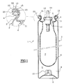
- the aerosol device 1 represented in FIG. 1 comprises an external container 2 having a bottom 9, and the upper part 3 of which ends substantially in dome shape.
- the dome ends with a rolled edge 4 delimiting an opening 5.
- a flexible bag 6, containing the product to be dispensed P, is disposed at inside the container 2.
- the annular chamber 8, between the pocket 6 and the external container 2 is filled with a propellant G.
- a valve 10 is arranged in the bottom 9 of the outer container so as to allow the introduction of the propellant into the annular volume 8.
- a disc-shaped part metallic, called "cup" 11 On the rolled edge 4 of the container, is mounted a disc-shaped part metallic, called "cup" 11.
- the dispensing valve 12 is fixed generally in the center of the cup 11 and is thus in the axis of the aerosol pocket.
- the valve 12 comprises a valve stem 14 whose actuation is generally carried out by means of a push button (not shown).
- the cup 11 has a peripheral flange 13 intended to ensure the fixing of the cup 11 by expansion, that is to say by deforming the cup 11 from the inside, so as to press it against the internal surface of the dome 3 of the outer container 2, the deformation generated causing the tightening of the flange 13 on the rolled edge 4.
- the seal between the flange 13 of the cup 11 and the rolled edge 4 of the container is generally provided by an elastic seal 20 which will be discussed in more detail later.
- the pocket 6 is fixed at the crimping of the cup 11 on the rolled edge 4, the pocket being suspended by its neck in the axis of the aerosol can.
- the pass of the pocket ends in its upper part with a rim 15 of dimension allowing on the one hand to be inserted in the collar 13 of the cup, and on the other hand part to rest on the rolled edge 4, via the seal 20.
- the rim 15 of the pocket 6 is clamped between the flange 13 of the cup 11 and the rolled edge 4.
- the assembly thus formed can be mounted in industry in a similar manner to that which is described in patent FR-A-2 310 287 to which reference was made above.
- the valve is opened, either by insertion either by tilting, via a distribution head in the form of a pushbutton.
- the pressure exerted by the propellant on the pocket acts and expels the product through the dispensing valve out of the pocket.
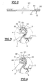
- the "magnifying glass" in Figure 1, as well as Figures 2 and 3 illustrate more specifies how the gas / product / exterior seal is obtained according to a first embodiment.
- the seal 20, as shown in the non-position mounted in Figure 2 is in the form of a flat annular element 21 comprising an inner annular part 23 of smaller thickness and a part outer annular 22 of greater thickness.
- a step 24 is thus formed between the inner annular part 23 and the outer annular part 22.
- the offset 24 is of height substantially equal to the thickness of the free edge 15 pocket 6.
- the seal 20 rests directly on the rolled edge 4 of the container 2. Due to the presence of the offset 24, when the free edge 15 of the pocket 6 rests on the portion internal annular 23 of the seal 20, the free edge does not form any excess thickness by relative to the upper surface of the outer annular part 22.
- the compression of seal 20 is substantially uniform over an annular zone extending both on one side of the recess 24, and on the other side of the offset 24.
- the seals between the annular volume 8 and outside, between the annular volume 8 and the pocket 6, and between the pocket 6 and the exterior is remarkable.
- the seal 20 is placed on the free edge 15 of the pocket 6.
- the inner annular part 23 of the seal 20 is in direct contact with the flange 13 of the cup 11.
- the seal 20 illustrated in FIG. 2 has been turned over.
- the free edge does not form extra thickness compared to the lower surface of the outer annular part 22.
- the compression of the seal 20 is substantially uniform over an area annular extending both on one side of the recess 24, and on the other side of the offset 24.
- the seals obtained are similar to those obtained with the previous variant.
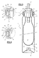
- FIG. 5 illustrates a second embodiment of the device according to the invention.
- the general configuration of device 1 is identical to that of device 1 of the Figure 1, and therefore does not require further description. It is note however that according to this embodiment, the cup 11 is mounted by external crimping of the flange 13 on the rolled edge 4.
- the difference between the two embodiments relates to the realization of the seals, in particular to the position of the offset. This difference between the two embodiments will be described in more detail with reference to the "magnifying glass" in FIG. 5.
- the seal 20 is of constant thickness.
- the rolled edge 4 forms a step 32 separating a inner annular portion 30 of thinner thickness, of an annular portion outer 31 of greater thickness.
- the difference in thickness corresponds substantially to the thickness of the free edge 15 of the pocket 6.
- the compression of the seal 20 is substantially uniform over an area annular extending partly, on one side of the recess 32, and partly, of the other side of the offset 32.
- the seals between the volume annular 8 and outside, between the annular volume 8 and the pocket 6, and between the pocket 6 and the outside, are remarkable.
- FIG. 4 being a variant of Figure 6.
- the seal 20 is, at rest, thick constant.
- the rolled edge 4 of the outer container 2 is also thick constant.
- the free edge 15 of the pocket 6 is disposed between the seal 20 and the edge rolled 4 of the outer container.
- the collar 13 includes an annular part inner 40 connected to an outer annular part 41 by a recess 42 whose height is substantially equal to the thickness of the free edge 15 of the pocket 6.
- a corresponding recess 43 exists inside the collar.
- the recesses 42 and 43 can be obtained by forming the metal during the strikes the collar.
- the seal 20 of thickness constant, is arranged between the free edge 15 of the pocket 6 and the rolled edge 4 of the outer container.
- the free edge 15 of the pocket 6 is disposed between the seal 20 and the flange 13 of the cup 11, in abutment against the step 43.
- the edge free 15 of the pocket 6 does not generate excess thickness relative to the surface internal of the collar 13.
- the compression of the seal 20 is substantially uniform over an annular zone extending in part on one side of the step 43, and partly on the other side of step 43.
- the results in terms of sealing are similar to those of the variant of FIG. 6.
Landscapes
- Chemical & Material Sciences (AREA)
- Dispersion Chemistry (AREA)
- Engineering & Computer Science (AREA)
- Mechanical Engineering (AREA)
- Containers And Packaging Bodies Having A Special Means To Remove Contents (AREA)
- Medicinal Preparation (AREA)
- Nozzles (AREA)
Abstract
Description
- les figures 1-3 illustrent un premier mode de réalisation du dispositif selon l'invention dans lequel le décrochement est formé par le joint d'étanchéité;
- la figure 4 illustre un second mode de réalisation du dispositif selon l'invention dans lequel le décrochement est formé par la coupelle porte-valve ;
- la figure 5 illustre un troisième mode de réalisation du dispositif selon l'invention dans lequel le décrochement est formé par le bord replié du récipient ; et
- la figure 6 est une variante de la figure 4.
Claims (17)
- Dispositif (1) pour le conditionnement et la distribution sous pression d'un produit (P) contenu dans une poche à parois souples (6) en communication avec une valve (12), ledit réservoir (6) étant disposé dans un récipient extérieur (2), un gaz propulseur (G) étant contenu dans le volume (8) formé entre le récipient extérieur (2) et la poche (6), ladite valve (12) étant montée sur une coupelle (11), des moyens (13) permettant la fixation de la coupelle (11) et d'un bord ouvert (15) de la poche (6), sur un bord (4) du récipient extérieur, un joint d'étanchéité (20) permettant, lorsqu'il est comprimé entre les moyens de fixation (13) et le bord (4) du récipient, de former étanchéité entre le gaz, le produit, et l'extérieur, un décrochement (24, 32, 43) étant formé, soit par le joint (20) en position non comprimée, soit par les moyens de fixation (13), soit par le bord (4) du récipient extérieur de manière à assurer une compression sensiblement uniforme d'au moins une partie du joint d'étanchéité (20), de part et d'autre dudit décrochement (24, 32, 42, 43).
- Dispositif selon la revendication 1 caractérisé en ce qu'une partie au moins (23) du joint d'étanchéité (20) est enserrée entre le bord (4) du récipient extérieur et le bord ouvert (15) de la poche (6), ou entre le bord ouvert (15) de la poche (6) et les moyens de fixation (13).
- Dispositif selon la revendication 2 caractérisé en ce que la partie (23) du joint d'étanchéité (20), enserrée entre le bord (4) du récipient extérieur et le bord ouvert (15) de la poche (6), ou entre le bord ouvert (15) de la poche (6) et les moyens de fixation (13), est constituée d'une partie annulaire intérieure (23) dudit joint d'étanchéité (20).
- Dispositif selon l'une quelconque des revendications 1 à 3 caractérisé en ce que le bord ouvert (15) de la poche (6) est disposé en regard du décrochement (24, 32, 43), et de préférence, sensiblement au contact de ce dernier.
- Dispositif selon l'une quelconque des revendications 1 à 4 caractérisé en ce que le joint d'étanchéité (20) est formé d'un élément distinct de la poche (6).
- Dispositif selon l'une quelconque des revendications 1 à 5 caractérisé en ce qu'une partie (22) du joint d'étanchéité (20) est enserrée directement entre le bord (4) du récipient et les moyens de fixation (13).
- Dispositif selon l'une quelconque des revendications 1 à 6 caractérisé en que ladite partie (22) du joint d'étanchéité (20), enserrée directement entre le bord (4) du récipient et les moyens de fixation (13), est formée d'une partie annulaire extérieure (22) du joint d'étanchéité (20).
- Dispositif (1) selon l'une quelconque des revendications 1 à 7 caractérisé en ce que le décrochement (24, 32, 43) est d'épaisseur sensiblement égale à l'épaisseur du bord ouvert (15) de la poche (6).
- Dispositif (1) selon l'une quelconque des revendications 1 à 8, caractérisé en ce que le décrochement (24) est formé par le joint d'étanchéité (20).
- Dispositif (1) selon la revendication 9 caractérisé en ce que le joint (20) est de forme annulaire, une portion annulaire intérieure (23) dudit joint étant d'épaisseur plus faible que l'épaisseur d'une portion annulaire extérieure (22) du joint.
- Dispositif (1) selon l'une quelconque des revendications 1 à 8 caractérisé en ce que le décrochement (43) est formé par un bord annulaire (13) replié de la coupelle (11), constituant lesdits moyens de fixation.
- Dispositif (1) selon l'une quelconque des revendications 1 à 8 caractérisé en ce que le décrochement (32) est formé par un bord annulaire replié (4) du récipient extérieur (2).
- Dispositif (1) selon la revendication 2 caractérisé en ce que le joint d'étanchéité (20) est disposé sur une partie (23) de sa largeur radiale entre le bord libre (15) de la poche (6) et les moyens de fixation (13).
- Dispositif (1) selon la revendication 2 caractérisé en ce que le joint d'étanchéité (20) est disposé sur une partie (23) de sa largeur radiale entre le bord libre (15) de la poche (6) et le bord (4) du récipient extérieur (2).
- Dispositif (1) selon l'une quelconque des revendications précédentes caractérisé en ce que l'épaisseur du décrochement (24, 32, 43) est comprise entre 0,03 mm et 1 mm, et de préférence, entre 0,1 mm et 0,5 mm.
- Dispositif (1) selon l'une quelconque des revendications 1 à 15 caractérisé en ce que la fixation de la coupelle (11) et du bord ouvert (15) de la poche (6), sur le bord (4) du récipient extérieur (2) est obtenue par sertissage.
- Dispositif (1) selon l'une quelconque des revendications 1 à 16 caractérisé en ce que la fixation de la coupelle (11) et du bord ouvert (15) de la poche (6), sur un bord (4) du récipient extérieur (2) est obtenue par dudgeonnage.
Applications Claiming Priority (2)
| Application Number | Priority Date | Filing Date | Title |
|---|---|---|---|
| FR0001489 | 2000-02-07 | ||
| FR0001489A FR2804665B1 (fr) | 2000-02-07 | 2000-02-07 | Aerosol a poche a etancheite amelioree |
Publications (2)
| Publication Number | Publication Date |
|---|---|
| EP1122190A1 true EP1122190A1 (fr) | 2001-08-08 |
| EP1122190B1 EP1122190B1 (fr) | 2007-04-04 |
Family
ID=8846717
Family Applications (1)
| Application Number | Title | Priority Date | Filing Date |
|---|---|---|---|
| EP01400084A Expired - Lifetime EP1122190B1 (fr) | 2000-02-07 | 2001-01-12 | Aérosol à poche à étanchéité améliorée |
Country Status (8)
| Country | Link |
|---|---|
| US (1) | US6332563B2 (fr) |
| EP (1) | EP1122190B1 (fr) |
| JP (1) | JP2001253483A (fr) |
| AT (1) | ATE358640T1 (fr) |
| CA (1) | CA2334417C (fr) |
| DE (1) | DE60127601T2 (fr) |
| ES (1) | ES2283382T3 (fr) |
| FR (1) | FR2804665B1 (fr) |
Cited By (2)
| Publication number | Priority date | Publication date | Assignee | Title |
|---|---|---|---|---|
| WO2013160338A3 (fr) * | 2012-04-27 | 2014-07-24 | Unilever Plc | Composition de spray topique et système permettant d'administrer cette dernière |
| US9457160B2 (en) | 2002-05-24 | 2016-10-04 | Btg International Limited | Container for the generation of therapeutic microfoam |
Families Citing this family (34)
| Publication number | Priority date | Publication date | Assignee | Title |
|---|---|---|---|---|
| DE19746018C2 (de) * | 1997-10-17 | 2000-12-21 | Lechner Gmbh | Verfahren zur Herstellung einer Zweikammerdruckpackung und Vorrichtung zur Durchführung des Verfahrens |
| JP4438983B2 (ja) * | 2003-07-03 | 2010-03-24 | 株式会社東海 | 燃料電池用燃料容器 |
| US7575133B2 (en) * | 2003-10-06 | 2009-08-18 | Crown Cork & Seal Technologies Corporation | Bi-can having internal bag |
| DE102004007121A1 (de) * | 2004-02-12 | 2005-09-08 | Heraeus Kulzer Gmbh | Verpackte fließfähige faserhaltige oder hochviskose Dentalmaterialien |
| US20070241132A1 (en) * | 2006-04-17 | 2007-10-18 | The Procter & Gamble Company | Pressurized package |
| DE102006027911A1 (de) * | 2006-06-01 | 2007-12-06 | Lindal Ventil Gmbh | Behälter zum Austragen eines Mediums |
| JP2009057110A (ja) * | 2007-08-06 | 2009-03-19 | Takeuchi Press Ind Co Ltd | 二重エアゾール容器 |
| JP5219131B2 (ja) * | 2008-04-25 | 2013-06-26 | 東洋製罐株式会社 | マウンティングカップのクリンチ部の構造 |
| US20100001020A1 (en) * | 2008-07-02 | 2010-01-07 | Ashley Louis S | method of attaching a soft plastic bag in an aerosol can, and other cans such as flat top cans |
| US20110168570A1 (en) * | 2010-01-12 | 2011-07-14 | 2140909 Ontario Inc., O/A Pathocept Corporation | System, method and apparatus for killing pathogens |
| WO2011101216A1 (fr) * | 2010-02-17 | 2011-08-25 | Kaltenbach & Voigt Gmbh | Réservoir pour la fourniture de fluides destinés à la désinfection, la stérilisation et/ou l'entretien d'instruments médicaux, en particulier d'instruments de dentisterie |
| WO2012006532A1 (fr) * | 2010-07-08 | 2012-01-12 | The Procter & Gamble Company | Dispositif pour distribuer de la matière |
| DE102010038912A1 (de) * | 2010-08-04 | 2012-02-09 | Huhtamaki Ronsberg Zn Der Huhtamaki Deutschland Gmbh & Co. Kg | Bag-on-Valve-System mit einem Füllgut-Behälter für aggressive Füllgüter, Füllgut-Behälter für ein Bag-on-Valve-System, Folienlaminat zur Herstellung eines Füllgut-Behälters und Verwendung des Folienlaminats für ein Bag-on-Valve-System |
| FR2981054B1 (fr) * | 2011-10-05 | 2015-01-16 | Valois Sas | Element de fixation d'un organe de distribution sur le col d'un recipient et dispositif de distribution de produit fluide comportant un tel element de fixation. |
| EP3154511B1 (fr) | 2014-06-16 | 2020-01-29 | The Procter and Gamble Company | Procédé de traitement des cheveux à l'aide d'un après-shampoing concentré |
| US9481505B2 (en) * | 2014-06-16 | 2016-11-01 | Michael Scott Fishman | Aerosol sodium chloride mixture agent with trigger sprayer |
| US9487342B2 (en) * | 2014-06-16 | 2016-11-08 | Michael Scott Fishman | Aerosol isopropyl alcohol mixture agent with trigger sprayer |
| EP3154506A1 (fr) | 2014-06-16 | 2017-04-19 | The Procter & Gamble Company | Procédé de traitement de cheveux utilisant un après-shampooing concentré |
| EP3154640B1 (fr) | 2014-06-16 | 2022-05-18 | The Procter & Gamble Company | Procédé de traitement de cheveux avec un après-shampooing concentré |
| KR101530907B1 (ko) * | 2014-12-26 | 2015-06-23 | 이충호 | 액상 용기 |
| CN107847767A (zh) | 2015-04-23 | 2018-03-27 | 宝洁公司 | 毛发护理调理组合物 |
| US10124951B2 (en) | 2015-12-15 | 2018-11-13 | The Procter And Gamble Company | Method of treating hair |
| WO2017106399A1 (fr) | 2015-12-15 | 2017-06-22 | The Procter & Gamble Company | Procédé de traitement des cheveux |
| US10265251B2 (en) | 2015-12-15 | 2019-04-23 | The Procter And Gamble Company | Method of treating hair |
| MX371218B (es) | 2015-12-15 | 2020-01-08 | Procter & Gamble | Método para tratar el cabello. |
| WO2017106404A1 (fr) | 2015-12-15 | 2017-06-22 | The Procter & Gamble Company | Procédé de traitement capillaire |
| MX371217B (es) | 2015-12-15 | 2020-01-08 | Procter & Gamble | Método para tratar cabello. |
| US10294013B2 (en) * | 2015-12-21 | 2019-05-21 | The Procter And Gamble Plaza | Package to dispense a foaming composition |
| MX384157B (es) | 2016-04-22 | 2025-03-14 | Procter & Gamble | Método para formar una capa de silicona. |
| WO2017184795A1 (fr) | 2016-04-22 | 2017-10-26 | The Procter & Gamble Company | Procédé de formation d'une couche de silicone |
| US10421086B1 (en) * | 2018-06-19 | 2019-09-24 | Christine Kuligowski | Reusable dry erase spray paint can |
| EP3876901B1 (fr) | 2018-11-08 | 2024-07-03 | The Procter & Gamble Company | Composition d'après-shampoing à faible contrainte de cisaillement comprenant des vésicules à réseaux de gels sphériques |
| GB2596321A (en) * | 2020-06-24 | 2021-12-29 | Pritchard Spray Ip Ltd | Methods for filling an aerosol dispenser |
| US20250256910A1 (en) * | 2024-02-09 | 2025-08-14 | Swimc Llc | Aerosol can |
Citations (4)
| Publication number | Priority date | Publication date | Assignee | Title |
|---|---|---|---|---|
| FR2341501A2 (fr) * | 1976-02-20 | 1977-09-16 | Cebal | Etancheite des aerosols a poche |
| EP0494004A1 (fr) * | 1990-12-31 | 1992-07-08 | L'oreal | Dispositif pour distribuer sous pression un produit, en particulier un produit moussant, et procédés de remplissage d'un récipient pour un tel dispositif |
| FR2710036A1 (fr) * | 1993-09-17 | 1995-03-24 | Sivel | Conditionnement composé d'un récipient rigide à l'intérieur duquel est monté un récipient déformable contenant un produit délivré par doses à l'aide d'une pompe. |
| WO1999016684A1 (fr) * | 1997-10-01 | 1999-04-08 | Osaka Shipbuilding Co., Ltd. | Contenant sous pression double conçu pour charger une sous-cupule et produits sous pression doubles utilisant ce contenant |
Family Cites Families (5)
| Publication number | Priority date | Publication date | Assignee | Title |
|---|---|---|---|---|
| FR2310287A1 (fr) | 1975-05-07 | 1976-12-03 | Cebal | Procede et appareillage pour obtenir l'etancheite de recipients dits aerosols a poche |
| US4117951A (en) | 1975-05-07 | 1978-10-03 | Cebal | Aerosol dispenser liner |
| GB2145775B (en) * | 1983-08-31 | 1987-08-05 | Metal Box Plc | Pressurisable containers |
| US5277336A (en) | 1990-12-31 | 1994-01-11 | L'oreal | Device for the pressurized dispensing of a product, especially a foaming product, and processes for filling a container for a device of this kind |
| AU5406596A (en) * | 1995-03-09 | 1996-10-08 | Precision Valve Corporation | Improved aerosol container closure |
-
2000
- 2000-02-07 FR FR0001489A patent/FR2804665B1/fr not_active Expired - Fee Related
-
2001
- 2001-01-12 AT AT01400084T patent/ATE358640T1/de not_active IP Right Cessation
- 2001-01-12 DE DE60127601T patent/DE60127601T2/de not_active Expired - Lifetime
- 2001-01-12 EP EP01400084A patent/EP1122190B1/fr not_active Expired - Lifetime
- 2001-01-12 ES ES01400084T patent/ES2283382T3/es not_active Expired - Lifetime
- 2001-02-06 CA CA002334417A patent/CA2334417C/fr not_active Expired - Fee Related
- 2001-02-07 JP JP2001031438A patent/JP2001253483A/ja active Pending
- 2001-02-07 US US09/777,865 patent/US6332563B2/en not_active Expired - Fee Related
Patent Citations (4)
| Publication number | Priority date | Publication date | Assignee | Title |
|---|---|---|---|---|
| FR2341501A2 (fr) * | 1976-02-20 | 1977-09-16 | Cebal | Etancheite des aerosols a poche |
| EP0494004A1 (fr) * | 1990-12-31 | 1992-07-08 | L'oreal | Dispositif pour distribuer sous pression un produit, en particulier un produit moussant, et procédés de remplissage d'un récipient pour un tel dispositif |
| FR2710036A1 (fr) * | 1993-09-17 | 1995-03-24 | Sivel | Conditionnement composé d'un récipient rigide à l'intérieur duquel est monté un récipient déformable contenant un produit délivré par doses à l'aide d'une pompe. |
| WO1999016684A1 (fr) * | 1997-10-01 | 1999-04-08 | Osaka Shipbuilding Co., Ltd. | Contenant sous pression double conçu pour charger une sous-cupule et produits sous pression doubles utilisant ce contenant |
Cited By (5)
| Publication number | Priority date | Publication date | Assignee | Title |
|---|---|---|---|---|
| US9457160B2 (en) | 2002-05-24 | 2016-10-04 | Btg International Limited | Container for the generation of therapeutic microfoam |
| WO2013160338A3 (fr) * | 2012-04-27 | 2014-07-24 | Unilever Plc | Composition de spray topique et système permettant d'administrer cette dernière |
| US8857741B2 (en) | 2012-04-27 | 2014-10-14 | Conopco, Inc. | Topical spray composition and system for delivering the same |
| EP3025762A1 (fr) * | 2012-04-27 | 2016-06-01 | Unilever PLC, a company registered in England and Wales under company no. 41424 of | Composition de spray topique et système permettant d'administrer cette dernière |
| EA026502B1 (ru) * | 2012-04-27 | 2017-04-28 | Юнилевер Н.В. | Распыляемая композиция для местного применения и система для ее доставки |
Also Published As
| Publication number | Publication date |
|---|---|
| CA2334417A1 (fr) | 2001-08-07 |
| FR2804665A1 (fr) | 2001-08-10 |
| ATE358640T1 (de) | 2007-04-15 |
| JP2001253483A (ja) | 2001-09-18 |
| EP1122190B1 (fr) | 2007-04-04 |
| DE60127601T2 (de) | 2007-12-13 |
| DE60127601D1 (de) | 2007-05-16 |
| CA2334417C (fr) | 2005-11-15 |
| US20010025857A1 (en) | 2001-10-04 |
| US6332563B2 (en) | 2001-12-25 |
| ES2283382T3 (es) | 2007-11-01 |
| FR2804665B1 (fr) | 2002-06-14 |
Similar Documents
| Publication | Publication Date | Title |
|---|---|---|
| EP1122190B1 (fr) | Aérosol à poche à étanchéité améliorée | |
| CA2368052C (fr) | Dispositif pressurise equipe d'une valve a basculement | |
| EP0549049B1 (fr) | Ensemble de distribution d'au moins un produit fluide | |
| CA2262135C (fr) | Ensemble de conditionnement et de distribution d'un produit liquide | |
| EP1131166B1 (fr) | Ensemble pour la distribution d'un produit pateux ou d'un gel | |
| FR2769595A1 (fr) | Tete de distribution a reprise d'air amelioree, et ensemble de conditionnement et de distribution equipe d'une telle tete | |
| EP0778225B1 (fr) | Récipient aérosol | |
| EP1208916B1 (fr) | Dispositif amélioré pour le conditionnement et la distribution dosée d'un produit liquide | |
| WO2000058021A1 (fr) | Poche et ensemble de conditionnement et de distribution | |
| FR2770834A1 (fr) | Dispositif de conditionnement et de distribution d'un produit fluide | |
| EP1673998B1 (fr) | Ensemble de conditionnement et d'application d'un produit cosmétique | |
| EP1038799A1 (fr) | Boíte d'aérosol à piston coulissant moulé et procédé de montage d'un tel ensemble | |
| FR2779205A1 (fr) | Valve et ensemble de conditionnement et de distribution equipe d'une telle valve | |
| FR2925032A1 (fr) | Valve pour recipient sous pression de stockage et de distribution de produit et recipient pourvu d'une telle valve | |
| EP1928612A1 (fr) | Distributeur de produit echantillon | |
| EP3055227B1 (fr) | Dispositif de distribution et de protection de fluide comportant un obturateur à fente | |
| EP4510978A1 (fr) | Recipient ophtalmique du type sans air | |
| EP3393298B1 (fr) | Pot de cosmétique comportant un système de mise sous pression d'un réservoir de réserve de produit | |
| EP0814914B1 (fr) | Dispositif de stockage et de distribution d'un produit, tel un produit cosmetique ou un parfum | |
| FR2724125A1 (fr) | Distributeur pour un produit liquide muni d'un piston et piston destine a equiper un tel distributeur | |
| FR2892397A1 (fr) | Dispositif de conditionnement et distribution d'un produit avec flacon muni d'une poche souple et d'un embout | |
| EP3468893A1 (fr) | Dispositif de distribution de produit fluide | |
| FR2546485A1 (fr) | Recipient pressurise du type " bombe aerosol " | |
| FR2714363A1 (fr) | Ensemble de distribution comprenant un récipient cylindrique comportant un piston à deux lèvres. | |
| FR2741933A1 (fr) | Valve pour dispositif de conditionnement et de distribution d'un liquide sous pression, et dispositif ainsi equipe |
Legal Events
| Date | Code | Title | Description |
|---|---|---|---|
| PUAI | Public reference made under article 153(3) epc to a published international application that has entered the european phase |
Free format text: ORIGINAL CODE: 0009012 |
|
| AK | Designated contracting states |
Kind code of ref document: A1 Designated state(s): AT BE CH CY DE DK ES FI FR GB GR IE IT LI LU MC NL PT SE TR |
|
| AX | Request for extension of the european patent |
Free format text: AL;LT;LV;MK;RO;SI |
|
| 17P | Request for examination filed |
Effective date: 20020208 |
|
| AKX | Designation fees paid |
Free format text: AT BE CH CY DE DK ES FI FR GB GR IE IT LI LU MC NL PT SE TR |
|
| GRAP | Despatch of communication of intention to grant a patent |
Free format text: ORIGINAL CODE: EPIDOSNIGR1 |
|
| GRAS | Grant fee paid |
Free format text: ORIGINAL CODE: EPIDOSNIGR3 |
|
| GRAA | (expected) grant |
Free format text: ORIGINAL CODE: 0009210 |
|
| AK | Designated contracting states |
Kind code of ref document: B1 Designated state(s): AT BE CH CY DE DK ES FI FR GB GR IE IT LI LU MC NL PT SE TR |
|
| PG25 | Lapsed in a contracting state [announced via postgrant information from national office to epo] |
Ref country code: FI Free format text: LAPSE BECAUSE OF FAILURE TO SUBMIT A TRANSLATION OF THE DESCRIPTION OR TO PAY THE FEE WITHIN THE PRESCRIBED TIME-LIMIT Effective date: 20070404 |
|
| REG | Reference to a national code |
Ref country code: GB Ref legal event code: FG4D Free format text: NOT ENGLISH |
|
| REG | Reference to a national code |
Ref country code: CH Ref legal event code: EP |
|
| REF | Corresponds to: |
Ref document number: 60127601 Country of ref document: DE Date of ref document: 20070516 Kind code of ref document: P |
|
| REG | Reference to a national code |
Ref country code: IE Ref legal event code: FG4D Free format text: LANGUAGE OF EP DOCUMENT: FRENCH |
|
| PG25 | Lapsed in a contracting state [announced via postgrant information from national office to epo] |
Ref country code: SE Free format text: LAPSE BECAUSE OF FAILURE TO SUBMIT A TRANSLATION OF THE DESCRIPTION OR TO PAY THE FEE WITHIN THE PRESCRIBED TIME-LIMIT Effective date: 20070704 |
|
| GBT | Gb: translation of ep patent filed (gb section 77(6)(a)/1977) |
Effective date: 20070621 |
|
| PG25 | Lapsed in a contracting state [announced via postgrant information from national office to epo] |
Ref country code: PT Free format text: LAPSE BECAUSE OF FAILURE TO SUBMIT A TRANSLATION OF THE DESCRIPTION OR TO PAY THE FEE WITHIN THE PRESCRIBED TIME-LIMIT Effective date: 20070904 |
|
| NLV1 | Nl: lapsed or annulled due to failure to fulfill the requirements of art. 29p and 29m of the patents act | ||
| REG | Reference to a national code |
Ref country code: ES Ref legal event code: FG2A Ref document number: 2283382 Country of ref document: ES Kind code of ref document: T3 |
|
| PG25 | Lapsed in a contracting state [announced via postgrant information from national office to epo] |
Ref country code: AT Free format text: LAPSE BECAUSE OF FAILURE TO SUBMIT A TRANSLATION OF THE DESCRIPTION OR TO PAY THE FEE WITHIN THE PRESCRIBED TIME-LIMIT Effective date: 20070404 |
|
| REG | Reference to a national code |
Ref country code: IE Ref legal event code: FD4D |
|
| PG25 | Lapsed in a contracting state [announced via postgrant information from national office to epo] |
Ref country code: IE Free format text: LAPSE BECAUSE OF FAILURE TO SUBMIT A TRANSLATION OF THE DESCRIPTION OR TO PAY THE FEE WITHIN THE PRESCRIBED TIME-LIMIT Effective date: 20070404 Ref country code: NL Free format text: LAPSE BECAUSE OF FAILURE TO SUBMIT A TRANSLATION OF THE DESCRIPTION OR TO PAY THE FEE WITHIN THE PRESCRIBED TIME-LIMIT Effective date: 20070404 Ref country code: DK Free format text: LAPSE BECAUSE OF FAILURE TO SUBMIT A TRANSLATION OF THE DESCRIPTION OR TO PAY THE FEE WITHIN THE PRESCRIBED TIME-LIMIT Effective date: 20070404 |
|
| PLBE | No opposition filed within time limit |
Free format text: ORIGINAL CODE: 0009261 |
|
| STAA | Information on the status of an ep patent application or granted ep patent |
Free format text: STATUS: NO OPPOSITION FILED WITHIN TIME LIMIT |
|
| 26N | No opposition filed |
Effective date: 20080107 |
|
| PG25 | Lapsed in a contracting state [announced via postgrant information from national office to epo] |
Ref country code: GR Free format text: LAPSE BECAUSE OF FAILURE TO SUBMIT A TRANSLATION OF THE DESCRIPTION OR TO PAY THE FEE WITHIN THE PRESCRIBED TIME-LIMIT Effective date: 20070705 |
|
| BERE | Be: lapsed |
Owner name: L'OREAL Effective date: 20080131 |
|
| PG25 | Lapsed in a contracting state [announced via postgrant information from national office to epo] |
Ref country code: MC Free format text: LAPSE BECAUSE OF NON-PAYMENT OF DUE FEES Effective date: 20080131 |
|
| REG | Reference to a national code |
Ref country code: CH Ref legal event code: PL |
|
| PG25 | Lapsed in a contracting state [announced via postgrant information from national office to epo] |
Ref country code: LI Free format text: LAPSE BECAUSE OF NON-PAYMENT OF DUE FEES Effective date: 20080131 Ref country code: CH Free format text: LAPSE BECAUSE OF NON-PAYMENT OF DUE FEES Effective date: 20080131 |
|
| PG25 | Lapsed in a contracting state [announced via postgrant information from national office to epo] |
Ref country code: BE Free format text: LAPSE BECAUSE OF NON-PAYMENT OF DUE FEES Effective date: 20080131 |
|
| PG25 | Lapsed in a contracting state [announced via postgrant information from national office to epo] |
Ref country code: CY Free format text: LAPSE BECAUSE OF FAILURE TO SUBMIT A TRANSLATION OF THE DESCRIPTION OR TO PAY THE FEE WITHIN THE PRESCRIBED TIME-LIMIT Effective date: 20070404 |
|
| PG25 | Lapsed in a contracting state [announced via postgrant information from national office to epo] |
Ref country code: LU Free format text: LAPSE BECAUSE OF NON-PAYMENT OF DUE FEES Effective date: 20080112 |
|
| PG25 | Lapsed in a contracting state [announced via postgrant information from national office to epo] |
Ref country code: TR Free format text: LAPSE BECAUSE OF FAILURE TO SUBMIT A TRANSLATION OF THE DESCRIPTION OR TO PAY THE FEE WITHIN THE PRESCRIBED TIME-LIMIT Effective date: 20070404 |
|
| PGFP | Annual fee paid to national office [announced via postgrant information from national office to epo] |
Ref country code: IT Payment date: 20110115 Year of fee payment: 11 Ref country code: FR Payment date: 20110128 Year of fee payment: 11 Ref country code: DE Payment date: 20110105 Year of fee payment: 11 |
|
| PGFP | Annual fee paid to national office [announced via postgrant information from national office to epo] |
Ref country code: GB Payment date: 20110112 Year of fee payment: 11 Ref country code: ES Payment date: 20110216 Year of fee payment: 11 |
|
| GBPC | Gb: european patent ceased through non-payment of renewal fee |
Effective date: 20120112 |
|
| REG | Reference to a national code |
Ref country code: FR Ref legal event code: ST Effective date: 20120928 |
|
| PG25 | Lapsed in a contracting state [announced via postgrant information from national office to epo] |
Ref country code: GB Free format text: LAPSE BECAUSE OF NON-PAYMENT OF DUE FEES Effective date: 20120112 Ref country code: DE Free format text: LAPSE BECAUSE OF NON-PAYMENT OF DUE FEES Effective date: 20120801 |
|
| REG | Reference to a national code |
Ref country code: DE Ref legal event code: R119 Ref document number: 60127601 Country of ref document: DE Effective date: 20120801 |
|
| PG25 | Lapsed in a contracting state [announced via postgrant information from national office to epo] |
Ref country code: IT Free format text: LAPSE BECAUSE OF NON-PAYMENT OF DUE FEES Effective date: 20120112 |
|
| PG25 | Lapsed in a contracting state [announced via postgrant information from national office to epo] |
Ref country code: FR Free format text: LAPSE BECAUSE OF NON-PAYMENT OF DUE FEES Effective date: 20120131 |
|
| REG | Reference to a national code |
Ref country code: ES Ref legal event code: FD2A Effective date: 20131023 |
|
| PG25 | Lapsed in a contracting state [announced via postgrant information from national office to epo] |
Ref country code: ES Free format text: LAPSE BECAUSE OF NON-PAYMENT OF DUE FEES Effective date: 20120113 |