EP1122208A2 - Verfahren und Einrichtung zum Steuern oder Regeln der Klemmkraft von Klammerarmen einer Transporteinrichtung - Google Patents
Verfahren und Einrichtung zum Steuern oder Regeln der Klemmkraft von Klammerarmen einer Transporteinrichtung Download PDFInfo
- Publication number
- EP1122208A2 EP1122208A2 EP01100199A EP01100199A EP1122208A2 EP 1122208 A2 EP1122208 A2 EP 1122208A2 EP 01100199 A EP01100199 A EP 01100199A EP 01100199 A EP01100199 A EP 01100199A EP 1122208 A2 EP1122208 A2 EP 1122208A2
- Authority
- EP
- European Patent Office
- Prior art keywords
- goods
- characteristic data
- transported
- transport device
- clamping force
- Prior art date
- Legal status (The legal status is an assumption and is not a legal conclusion. Google has not performed a legal analysis and makes no representation as to the accuracy of the status listed.)
- Withdrawn
Links
- 238000000034 method Methods 0.000 title claims abstract description 21
- 230000001105 regulatory effect Effects 0.000 claims abstract description 20
- 238000004806 packaging method and process Methods 0.000 claims description 19
- 230000001133 acceleration Effects 0.000 claims description 7
- 230000001276 controlling effect Effects 0.000 claims description 4
- 238000009826 distribution Methods 0.000 claims description 4
- 238000012545 processing Methods 0.000 claims description 4
- 238000001514 detection method Methods 0.000 claims description 3
- 239000000725 suspension Substances 0.000 claims 1
- 239000000463 material Substances 0.000 abstract description 4
- 238000007639 printing Methods 0.000 description 4
- 238000003860 storage Methods 0.000 description 4
- 230000000875 corresponding effect Effects 0.000 description 3
- 230000004888 barrier function Effects 0.000 description 2
- 238000004064 recycling Methods 0.000 description 2
- 238000012360 testing method Methods 0.000 description 2
- 238000002604 ultrasonography Methods 0.000 description 2
- 239000000853 adhesive Substances 0.000 description 1
- 230000001070 adhesive effect Effects 0.000 description 1
- 235000013361 beverage Nutrition 0.000 description 1
- 230000005540 biological transmission Effects 0.000 description 1
- 230000015572 biosynthetic process Effects 0.000 description 1
- 230000008859 change Effects 0.000 description 1
- 230000002596 correlated effect Effects 0.000 description 1
- 238000013461 design Methods 0.000 description 1
- 238000010586 diagram Methods 0.000 description 1
- 230000000694 effects Effects 0.000 description 1
- 238000005516 engineering process Methods 0.000 description 1
- 230000002349 favourable effect Effects 0.000 description 1
- 239000012530 fluid Substances 0.000 description 1
- 238000003780 insertion Methods 0.000 description 1
- 230000037431 insertion Effects 0.000 description 1
- 230000003993 interaction Effects 0.000 description 1
- 238000012432 intermediate storage Methods 0.000 description 1
- 230000007257 malfunction Effects 0.000 description 1
- 238000007726 management method Methods 0.000 description 1
- 238000004519 manufacturing process Methods 0.000 description 1
- 239000003550 marker Substances 0.000 description 1
- 238000005259 measurement Methods 0.000 description 1
- 230000003287 optical effect Effects 0.000 description 1
- 238000005457 optimization Methods 0.000 description 1
- 238000012856 packing Methods 0.000 description 1
- 239000003973 paint Substances 0.000 description 1
- 230000008569 process Effects 0.000 description 1
- 238000004886 process control Methods 0.000 description 1
- 238000003908 quality control method Methods 0.000 description 1
- 230000008054 signal transmission Effects 0.000 description 1
- 238000005406 washing Methods 0.000 description 1
Images


Classifications
-
- B—PERFORMING OPERATIONS; TRANSPORTING
- B66—HOISTING; LIFTING; HAULING
- B66F—HOISTING, LIFTING, HAULING OR PUSHING, NOT OTHERWISE PROVIDED FOR, e.g. DEVICES WHICH APPLY A LIFTING OR PUSHING FORCE DIRECTLY TO THE SURFACE OF A LOAD
- B66F9/00—Devices for lifting or lowering bulky or heavy goods for loading or unloading purposes
- B66F9/06—Devices for lifting or lowering bulky or heavy goods for loading or unloading purposes movable, with their loads, on wheels or the like, e.g. fork-lift trucks
- B66F9/075—Constructional features or details
- B66F9/12—Platforms; Forks; Other load supporting or gripping members
- B66F9/18—Load gripping or retaining means
- B66F9/183—Coplanar side clamps
-
- B—PERFORMING OPERATIONS; TRANSPORTING
- B66—HOISTING; LIFTING; HAULING
- B66F—HOISTING, LIFTING, HAULING OR PUSHING, NOT OTHERWISE PROVIDED FOR, e.g. DEVICES WHICH APPLY A LIFTING OR PUSHING FORCE DIRECTLY TO THE SURFACE OF A LOAD
- B66F9/00—Devices for lifting or lowering bulky or heavy goods for loading or unloading purposes
- B66F9/06—Devices for lifting or lowering bulky or heavy goods for loading or unloading purposes movable, with their loads, on wheels or the like, e.g. fork-lift trucks
- B66F9/075—Constructional features or details
- B66F9/12—Platforms; Forks; Other load supporting or gripping members
- B66F9/18—Load gripping or retaining means
- B66F9/184—Roll clamps
Definitions
- the invention relates to a method for controlling or regulating the clamping force of clamp arms moved against each other by a drive a transport device for individual or a group of like Transport goods taking into account the strength of the transport goods.
- DE 908 471 C is a forklift with gripper or clamp arms known in which the clamping force depends on the weight alone sets. This is done by a mirror-symmetrical arrangement of angle levers, on one lever arm of which the lifting force acts and whose other lever arms act on jaws that are in their centers are articulated and on the goods in the form of stacks of boxes act.
- Existing tension springs are not used to limit the Clamping force, but for pushing back the clamp arms that only on the bottom boxes act. This leads to the fact that with a Increasing the stack weight or the stack height increases the clamping force automatically increases without taking into account the strength of the lower boxes is taken.
- EP 0 443 998 A1 and EP 0 664 272 A2 are transport devices known with bracket arms, in which a test stroke was first carried out needs to be checked to see if the cargo, preferably Paper rolls for printers, slip in the clamp arms. This sliding process is detected by a feeler roller, which in one of the Bracket arms is arranged and the angle of rotation of the hydraulic drive controls in such a way that the clamping force when slipping is increased until the slipping no longer occurs.
- EP 0 664 272 A2 describes the slip detection by an additional device-side recording of the weight of the transported goods supplemented by a Limitation of the clamping force according to weight and any Cause the goods to slide.
- a “transponder” (an artificial word from “transmit” and “respond”) is part a combination of a reader and the transponder, between which data is exchanged inductively via an "air” interface become.
- the English name is “RFID”, the abbreviation for "Radio Frequency Identification”.
- RFID Radio Frequency Identification
- the invention has for its object measures and to specify means with which a Coordination of the essential mechanical characteristics of the transported goods and / or its packaging with the control of the clamping force the drive of a transport device is made possible.
- the task is solved in full, i.e. measures and means are specified with which on the basis of a wireless dialogue a coordination of the essential mechanical Characteristics of the goods to be transported and / or their packaging the control of the clamping force of the drive of a transport device is enabled and optimized.
- the invention also relates to a transport device with one another Clamp arms that can be moved by a drive for individual transport goods or a group of similar goods and with one Drive and a device for controlling or regulating the clamping force of the clamp arms taking into account the strength of the goods to be transported.
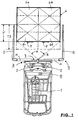
- FIG. 1 shows a vehicle 1 designed as a forklift truck with a telescopic mast 2 and a lifting carriage 3 shown on the a transport device 4 is attached with two bracket arms 5, the arranged mirror-symmetrically to a central longitudinal axis of the forklift are.
- Transport goods 6 are arranged in front of the forklift (thick edged), which also consists of four individual goods 6a, 6b, 6c and 6d can exist, which are arranged in two rows.
- Such an arrangement is described in DE 38 01 133 C2, which is expressly in the Disclosure content of this property right is included.
- This font also discloses the hydraulic drive in the transport device 4 is integrated and is therefore no longer described in detail here.
- the entry depth "T” does not exceed or fall below a minimum.
- the front row with the goods 6c and 6d would indeed reliably clamped, but not the back row with the goods to be transported 6a and 6b which, when lifting the load from the clamp arms 5 could slip out or tip out.
- Analogous considerations apply also for a single large cargo 6. significant, that the edges of a package by their angular position have greater resistance to deformation than the walls of the Packaging.
- a receiver on the lifting carriage or on the transport device 8 attached the optical axis of which is either at an angle " ⁇ " is pivotable or has a corresponding perspective and through the front of the cargo 6 or the cargo 6c and 6d can be scanned, on which code devices 9 are attached.
- code devices 9 can either be from a printed or glued on strip code (bar code) or plain text or from a transponder that has at least characteristics over the minimum and the maximum permissible clamping force on the special transport goods 6, 6a, 6b, 6c and 6d.
- the transponder can be a "read-only" transponder or be a writable transponder.
- the receiver 8 also a transmitter, which is stored in the transponder retrieves data and / or stores new data. For reading from Streak codes or plain text will suitably be given to the recipient Assigned light source.
- Such transmitters and receivers or readers in a dialogue with the code device 9 enter are commercially available, so that there is no need to go into detail about this.
- the limits for the clamping force can also be advantageous in the code devices 9 the following characteristics are stored: the number and spatial arrangement (side by side and / or one behind the other) of the goods to be transported Weight (individual weight and / or total weight), the dimensions (Individual dimensions and / or overall dimensions), the coefficient of friction of the cargo 6 ff.
- the Coefficient of friction of the transport goods from the shipper and the Coefficient of friction of the clamp arms from the manufacturer of the transport device to be specified and coordinated the strength of the cargo against clamping forces of the clamp arms, namely the Transport goods if it is to be transported unpacked and the Packaging with the content when the goods are transported packed should be, the content (article numbers) of the packaging, the location at the sender, the delivery address of the recipient, the delivery time, the limit values for the depth of entry of the cargo between the Brackets and the limit values for the clamping force.
- the exchange of goods between the sender and recipient of the goods Data can - after printing - the usual shipping documents replace.
- the vehicle 1 and / or the transport device 4 are with a Central unit 10 provided, the details of which are given below 5 are explained.
- this central unit 10 the respective required parameters correlated with each other using a computer to ensure reliable control of the transport device and to ensure reliable transport of the cargo.
- the weakest Links in the power chain are always the points of attack of the clamp arms, if these are smaller than the areas on which they attack.
- Transponders can also be covered, e.g. inside of packaging, or on the side surfaces or top and back sides of the goods to be transported because the signal transmission here by electromagnetic waves (e.g. with radio or medium frequency) he follows. It is assumed that there is no shielding through metallic walls or close-meshed grids (Faraday cage) he follows.
- transponders are expensive in relation to adhesive labels, it is recommended their use preferably in reusable packaging or in removable form for reuse.
- FIGS. 2 and 3 show clamp arms 5 projecting downwards Trapezoidal shape, which linear guides 11 towards and in front of each other are movable away, in Figure 2 perpendicular to the plane of the drawing and parallel to this in FIG. 3. It is driven by a hydraulic drive 12 with counter-acting hydraulic cylinders 13 (see also Figure 5). Such an arrangement is - albeit in a different spatial position, namely with horizontally protruding clamp arms - in the DE 44 33 050 A1 describes the expressly in the disclosure content this property right is included. This document also discloses the hydraulic drive, which is integrated in the transport device 4 and is therefore no longer described in detail here.
- the hydraulic drive can also be powered by an accumulator 14 can be supplied.
- the clamp arms are inside with anti-slip pads 15 provided.
- the linear guides 11 are on the undersides of hollow profiles 16 attached, which are used as insertion pockets for forklift forks, not shown are designed so that a conventional forklift as a vehicle 1st can be used.
- FIG. 4 shows a side view of the front part of a vehicle 1 a mast 2, which can be pivoted in the direction of the upper double arrow is, and with a transport device 4a for cylindrical cargo 6e, e.g. a paper roll for printing machines.
- the transport device 4a also has two clamp arms 5 and is by itself one known rotary drive about an axis A pivotable. So that will usually the cargo 6e with the vertical axis of the cargo recorded, rotated and transported with a horizontal axis and then parked again with a vertical axis or directly in one Printing machine mounted.
- Vertical storage - also in columnar form Stacking - serves to avoid deformation under the Own weight.
- This vehicle 1 also has one that is not visible here Control and regulating device with the manner already described according to the read data of a code device and / or vehicle-side data a necessary but not excessive clamping force the clamp arms can be generated.
- FIG. 5 shows the main in a very schematic representation Drive elements and the control and regulating device 18.
- To drive 12 include two oppositely acting hydraulic cylinders 13, which by Control valves 17, 19 and 20 controlled and by means of a hydraulic unit 21 are supplied with hydraulic fluid.
- the control valves 17, 18 and 20 are commercially available components, namely the control valve 17 is a hydraulically unlockable check valve and the control valve 19 is a proportionally controlled pressure relief valve as in the company brochure BOSCH "Proportional valves without / with built-in electronics ", edition 1.95. The mode of operation this valve relies on the variable force of a proportional magnet compared to that of a spring.
- the one from this Comparison of the resulting path (position) corresponds to a pressure setting or in the case of throttle and directional control valve, a throttle cross section and thus a volume flow.
- This is a stepless or proportional Regulation of the clamping force of the clamp arms 5 in accordance with the data processing possible.
- a receiver 22 for querying the code device (s) is connected to the central unit 10. 9 and a sensor 23 for determining the entry depth "T" connected.
- the sensor 23 can be emitted by means of light Formation of light barriers or ultrasound with reflection measurement be operated as described in DE 38 01 133 C2.
- the Operation of the receiver 22 and data processing has been detailed already described above.
- an input device 24 e.g. a keyboard
- new data and commands can be entered.
- a display device 25 e.g.
- the critical time is in any case the time when the Transport goods from the floor space and set down on a new one Footprint, because in these cases the mass forces are added to the weights add when accelerating and decelerating. Add to that still vertical forces due to vehicle movements over uneven ground.
- These factors can also - depending on the design the transport device 4 and 4a and / or the central unit 10 with corresponding safety surcharges based on measured values in associated computers are taken into account. Acceleration and Deceleration values due to vehicle movements can use appropriate sensors on the vehicle or chassis be measured and evaluated. This means that it can be done in a split second increase and maintain the clamping forces.
- Transport goods coded in this way can also be used for intermediate storage and / or at the recipient with appropriately or analogously equipped Transport devices resumed and / or transported further become.
- the invention can also be used in gripping devices, which are also hung on a crane bridge, for example.
Landscapes
- Engineering & Computer Science (AREA)
- Transportation (AREA)
- Structural Engineering (AREA)
- Civil Engineering (AREA)
- Life Sciences & Earth Sciences (AREA)
- Geology (AREA)
- Mechanical Engineering (AREA)
- Forklifts And Lifting Vehicles (AREA)
Abstract
Description
- Aufsatz "Es muß nicht immer Barcode sein" in LOGISTIK>HEUTE<, 11-98, Seiten 96/97;
- Firmendruckschrift "Baumer/IDENT "Elektronische Lagerplatzmarkierung und automatische Transportgutidentifikation ...";
- Firmendruckschrift "Baumer/IDENT "Auto-ID Systeme", 1998;
- Aufsatz von Forslund "Berührungsloses Identifizieren - Sichere Lagerlogistik in der Papierindustrie", veröffentlicht in "Betriebstechnik aktuell" 39 (1998) Seiten 34/35;
- Aufsatz von Forslund "Barcode und Transponder stellen die Lagerlogistik" veröffentlicht in "INDUSTRIEANZEIGER 37/99, Seite 84;
- Aufsatz von Forslund "Zwei Systeme ein Ziel: Barcode und Transponder im Lager" veröffentlicht in "F+H Fördern und Heben" 48 (1998) Seiten 845/846.
- die Code-Einrichtung aus der Gruppe der Streifen-Codes und der Transponder auswählt,
- die Code-Einrichtung zusätzlich mit Kenndaten über das Gewicht des Transportguts versieht,
- die Code-Einrichtung zusätzlich mit Kenndaten über die Anordnung, die Anzahl und die räumliche Verteilung des Transportguts versieht,
- die Code-Einrichtung zusätzlich mit Kenndaten über die Abmessungen des Transportguts versieht,
- die Code-Einrichtung zusätzlich mit Kenndaten über den Reibungskoeffizienten zwischen den Klammerarmen und dem Transportgut versieht,
- fahrzeugseitig Beschleunigungs- und/oder Verzögerungskräfte mißt und die Klemmkraft der Klammerarme nach Maßgabe dieser Meßwerte erhöht,
- die Erhöhung der Klemmkraft nach Maßgabe der von der Code-Einrichtung erhaltenen Festigkeits-Kenndaten begrenzt,
- die Code-Einrichtung zusätzlich mit Kenndaten über den Inhalt von Verpackungen versieht,
- die Code-Einrichtung zusätzlich mit Kenndaten über den Standort des Transportguts versieht,
- die Code-Einrichtung zusätzlich mit Kenndaten über den Empfänger des Transportguts versieht,
- die Code-Einrichtung zusätzlich mit Kenndaten über den Lieferzeitpunkt des Transportguts versieht,
- zusätzlich die Einfahrtiefe des Transportguts zwischen die Klammerarme bestimmt und die Klemmkraft nach Maßgabe der Einfahrtiefe begrenzt,
- als Antrieb für die Klammerarme einen Hydraulikantrieb verwendet und den Druck im Hydraulikantrieb nach Maßgabe der Kenndaten steuert oder regelt und/oder, wenn man
- für die Regelung der Klemmkraft der Klammerarme proportional gesteuerte Druckbegrenzungsventile verwendet.
- die Code-Einrichtung aus der Gruppe der Streifen-Codes und der Transponder ausgewählt ist,
- die Code-Einrichtung zusätzlich mit Kenndaten über das Gewicht des Transportguts versehen ist,
- die Code-Einrichtung zusätzlich mit Kenndaten über die Anordnung, die Anzahl und die räumliche Verteilung des Transportguts versehen ist,
- die Code-Einrichtung zusätzlich mit Kenndaten über die Abmessungen des Transportguts versehen ist,
- die Code-Einrichtung zusätzlich mit Kenndaten über den Reibungskoeffizienten zwischen den Klammerarmen und dem Transportgut versehen ist,
- fahrzeugseitig Sensoren für die Messung von Beschleunigungs- und/oder Verzögerungskräfte vorgesehen sind und wenn die Klemmkraft nach Maßgabe der Meßwerte vergrößerbar ist,
- die Erhöhung der Klemmkraft nach Maßgabe der von der Code-Einrichtung erhaltenen Festigkeits-Kenndaten begrenzbar ist,
- die Code-Einrichtung zusätzlich mit Kenndaten über den Inhalt von Verpackungen versehen ist,
- die Code-Einrichtung zusätzlich mit Kenndaten über den Standort des Transportguts versehen ist,
- die Code-Einrichtung zusätzlich mit Kenndaten über den Empfänger des Transportguts versehen ist,
- die Code-Einrichtung zusätzlich mit Kenndaten über den Lieferzeitpunkt des Transportguts versehen ist,
- zusätzlich Sensoren für die Bestimmung der Einfahrtiefe des Transportguts zwischen die Klammerarme vorgesehen sind und wenn die Klemmkraft nach Maßgabe der Einfahrtiefe begrenzbar ist,
- der Antrieb für die Klammerarme ein Hydraulikantrieb ist, bei dem der Druck im Hydraulikantrieb nach Maßgabe der Kenndaten und/oder der Einfahrtiefe steuer- oder regelbar ist, insbesondere wenn zur Regelung der Klemmkraft der Klammerarme proportional gesteuerte Druckberenzungsventile vorgesehen sind,
- der Antrieb für die Klammerarme ein elektromechischer Antrieb ist, bei dem die Klemmkraft nach Maßgabe der Kenndaten und/oder der Einfahrtiefe steuer- oder regelbar ist, und/oder, wenn
- die Transporteinrichtung an ein Fahrzeug, insbesondere an einen Hubmast eines Hubstaplers angebaut ist.
- Figur 1
- eine Draufsicht auf ein erstes Ausführungsbeispiel mit einem Hubstapler mit einer Transporteinrichtung mit waagrecht in Fahrtrichtung abstehenden Klammerarmen im Zusammenwirken mit einem Transportgut oder mehreren Transportgütern,
- Figur 2
- eine Seitenansicht eines zweiten Ausführungsbeispiels mit einer hängenden Transporteinrichtung,
- Figur 3
- eine Draufsicht des Gegenstandes nach Figur 2 in Richtung des Pfeils III in Figur 2,
- Figur 4
- eine Seitenansicht eines dritten Ausführungsbeispiels mit einer drehbaren Transporteinrichtung für zylindrisches Transport, z.B. eine Papierrolle für Druckmaschinen und
- Figur 5
- ein Prinzipschaltbild einer Steueranordnung für die Ausführungsbeispiele nach den Figuren 1, 2/3 und 4.
- 1
- Fahrzeug
- 2
- Hubmast
- 3
- Hubschlitten
- 4
- Transporteinrichtung
- 4a
- Transporteinrichtung
- 5
- Klammerarme
- 6
- Transportgut
- 6a
- Transportgut
- 6b
- Transportgut
- 6c
- Transportgut
- 6d
- Transportgut
- 6e
- Transportgut
- 7
- Transporteinrichtung
- 8
- Empfänger
- 9
- Code-Einrichtungen
- 10
- Zentraleinheit
- 11
- Linearführungen
- 12
- Hydraulikantrieb
- 13
- Hydraulikzylindern
- 14
- Akkumulator
- 15
- Anti-Gleitbeläge
- 16
- Hohlprofile (Einschubtaschen)
- 17
- Steuerventil
- 18
- Steuer- und Regeleinrichtung
- 19
- Steuerventil
- 20
- Steuerventile
- 21
- Hydraulikaggregat
- 22
- Empfänger
- 23
- Sensor
- 24
- Eingabeeinrichtung
- 25
- Anzeigeeinrichtung
- 26
- Schallerzeuger
- A
- Achse
- T
- Einfahrtiefe
- T2
- Einfahrtiefe
Claims (34)
- Verfahren zum Steuern oder Regeln der Klemmkraft von gegeneinander durch einen Antrieb (12) bewegten Klammerarmen (5) einer Transporteinrichtung (4, 4a) für einzelne Transportgüter (6, 6e) oder eine Gruppe von gleichartigen Transportgütern (6a, 6b, 6c, 6d) unter Berücksichtigung der Festigkeit der Transportgüter, dadurch gekennzeichnet, daß mana) mindestes ein Transportgut mit einer Code-Einrichtung (9) mit Kenndaten über die Festigkeit des Transportguts in Richtung der Klemmkraft versieht, undb) die Kenndaten der Code-Einrichtung (9) mittels eines der Transporteinrichtung (4, 4a) zugeordneten Empfängers (8) erfaßt und die Klemmkraft nach Maßgabe der Kenndaten steuert oder regelt.
- Verfahren nach Anspruch 1, dadurch gekennzeichnet, daß man die Code-Einrichtung (9) aus der Gruppe der Streifen-Codes und der Transponder auswählt.
- Verfahren nach Anspruch 1, dadurch gekennzeichnet, daß man die Code-Einrichtung (9) zusätzlich mit Kenndaten über das Gewicht des Transportguts versieht.
- Verfahren nach Anspruch 1, dadurch gekennzeichnet, daß man die Code-Einrichtung (9) zusätzlich mit Kenndaten über die Anordnung, die Anzahl und die räumliche Verteilung des Transportguts (6a, 6b, 6c, 6d) versieht.
- Verfahren nach Anspruch 1, dadurch gekennzeichnet, daß man die Code-Einrichtung (9) zusätzlich mit Kenndaten über die Abmessungen des Transportguts (6; 6a, 6b, 6c, 6d) versieht.
- Verfahren nach Anspruch 1, dadurch gekennzeichnet, daß man die Code-Einrichtung (9) zusätzlich mit Kenndaten über den Reibungskoeffizienten zwischen den Klammerarmen (5) und dem Transportgut versieht.
- Verfahren nach Anspruch 1, dadurch gekennzeichnet, daß man fahrzeugseitig Beschleunigungs- und/oder Verzögerungskräfte mißt und die Klemmkraft der Klammerarme nach Maßgabe dieser Meßwerte erhöht.
- Verfahren nach Anspruch 7, dadurch gekennzeichnet, daß man die Erhöhung der Klemmkraft nach Maßgabe der von der Code-Einrichtung (9) erhaltenen Festigkeits-Kenndaten begrenzt.
- Verfahren nach Anspruch 1, dadurch gekennzeichnet, daß man die Code-Einrichtung (9) zusätzlich mit Kenndaten über den Inhalt von Verpackungen versieht.
- Verfahren nach Anspruch 1, dadurch gekennzeichnet, daß man die Code-Einrichtung (9) zusätzlich mit Kenndaten über den Standort des Transportguts versieht.
- Verfahren nach Anspruch 1, dadurch gekennzeichnet, daß man die Code-Einrichtung (9) zusätzlich mit Kenndaten über den Empfänger des Transportguts versieht.
- Verfahren nach Anspruch 1, dadurch gekennzeichnet, daß man die Code-Einrichtung (9) zusätzlich mit Kenndaten über den Lieferzeitpunkt des Transportguts versieht.
- Verfahren nach Anspruch 1, dadurch gekennzeichnet, daß man zusätzlich die Einfahrtiefe (T) des Transportguts (6; 6a, 6b, 6c, 6d, 6e) zwischen die Klammerarme (5) bestimmt und die Klemmkraft nach Maßgabe der Einfahrtiefe (T) begrenzt.
- Verfahren nach mindestens einem der Ansprüche 1 bis 13, dadurch gekennzeichnet, daß man als Antrieb (12) für die Klammerarme (5) einen Hydraulikantrieb verwendet und den Druck im Hydraulikantrieb nach Maßgabe der Kenndaten steuert oder regelt.
- Verfahren nach Anspruch 14, dadurch gekennzeichnet, daß man für die Regelung der Klemmkraft der Klammerarme (5) proportional gesteuerte Druckbegrenzungsventile (19) verwendet.
- Transporteinrichtung mit gegeneinander durch einen Antrieb (12) bewegbaren Klammerarmen (5) für einzelne Transportgüter (6, 6e) oder eine Gruppe von gleichartigen Transportgütern (6a, 6b, 6c, 6d) und mit einem Antrieb (12) und einer Einrichtung zum Steuern oder Regeln der Klemmkraft der Klammerarme (5) unter Berücksichtigung der Festigkeit der Transportgüter,
dadurch gekennzeichnet, daßa) mindestes ein Transportgut mit einer Code-Einrichtung (9) mit Kenndaten über die Festigkeit des Transportguts in Richtung der Klemmkraft versehen ist, und daßb) die Transporteinrichtung einen Empänger (8) für die Erfassung und eine Steuer- oder Regeleinrichtung (18) für die Verarbeitung der Kenndaten der Code-Einrichtung (9) besitzt, wobei der Antrieb (12) durch diese Steuer- oder Regeleinrichtung (18) in der Weise beeinflußbar ist, daß die Klemmkraft nach Maßgabe der Kenndaten steuerbar oder regelbar ist. - Transporteinrichtung nach Anspruch 16, dadurch gekennzeichnet, daß die Code-Einrichtung (9) aus der Gruppe der Streifen-Codes und der Transponder ausgewählt ist.
- Transporteinrichtung nach Anspruch 16, dadurch gekennzeichnet, daß die Code-Einrichtung (9) zusätzlich mit Kenndaten über das Gewicht des Transportguts versehen ist.
- Transporteinrichtung nach Anspruch 16, dadurch gekennzeichnet, daß die Code-Einrichtung (9) zusätzlich mit Kenndaten über die Anordnung, die Anzahl und die räumliche Verteilung des Transportguts (6a, 6b, 6c, 6d) versehen ist.
- Transporteinrichtung nach Anspruch 16, dadurch gekennzeichnet, daß die Code-Einrichtung (9) zusätzlich mit Kenndaten über die Abmessungen des Transportguts (6; 6a, 6b, 6c, 6d) versehen ist.
- Transporteinrichtung nach Anspruch 16, dadurch gekennzeichnet, daß die Code-Einrichtung (9) zusätzlich mit Kenndaten über den Reibungskoeffizienten zwischen den Klammerarmen (5) und dem Transportgut (6; 6a, 6b, 6c 6c) versehen ist.
- Transporteinrichtung nach Anspruch 16, dadurch gekennzeichnet, daß fahrzeugseitig Sensoren für die Messung von Beschleunigungs- und/oder Verzögerungskräfte vorgesehen sind und daß die Klemmkraft nach Maßgabe der Meßwerte vergrößerbar ist.
- Transporteinrichtung nach Anspruch 22, dadurch gekennzeichnet, daß die Erhöhung der Klemmkraft nach Maßgabe der von der Code-Einrichtung (9) erhaltenen Festigkeits-Kenndaten begrenzbar ist.
- Transporteinrichtung nach Anspruch 16, dadurch gekennzeichnet, daß die Code-Einrichtung (9) zusätzlich mit Kenndaten über den Inhalt von Verpackungen versehen ist.
- Transporteinrichtung nach Anspruch 16, dadurch gekennzeichnet, daß die Code-Einrichtung (9) zusätzlich mit Kenndaten über den Standort des Transportguts versehen ist.
- Transporteinrichtung nach Anspruch 16, dadurch gekennzeichnet, daß die Code-Einrichtung (9) zusätzlich mit Kenndaten über den Empfänger des Transportguts versehen ist.
- Transporteinrichtung nach Anspruch 16, dadurch gekennzeichnet, daß die Code-Einrichtung (9) zusätzlich mit Kenndaten über den Lieferzeitpunkt des Transportguts versehen ist.
- Transporteinrichtung nach Anspruch 16, dadurch gekennzeichnet, daß zusätzlich Sensoren (23) für die bestimmung der Einfahrtiefe (T) des Transportguts (6; 6a, 6b, 6c, 6d) zwischen die Klammerarme (5) vorgesehen sind und daß die Klemmkraft nach Maßgabe der Einfahrtiefe begrenzbar ist.
- Transporteinrichtung nach mindestens einem der Ansprüche 16 bis 28, dadurch gekennzeichnet, daß der Antrieb (12) für die Klammerarme (5) ein Hydraulikantrieb ist, bei dem der Druck im Hydraulikantrieb nach Maßgabe der Kenndaten und/oder der Einfahrtiefe (T) steuer- oder regelbar ist.
- Transporteinrichtung nach Anspruch 29, dadurch gekennzeichnet, daß zur Regelung der Klemmkraft der Klammerarme (5) proportional gesteuerte Druckberenzungsventile (19) vorgesehen sind.
- Transporteinrichtung nach mindestens einem der Ansprüche 16 bis 28, dadurch gekennzeichnet, daß der Antrieb (12) für die Klammerarme (5) ein elektromechanischer Antrieb ist, der nach Maßgabe der Kenndaten und/oder der Einfahrtiefe (T) steuer- oder regelbar ist.
- Transporteinrichtung nach Anspruch 16, gekennzeichnet durch ihren Anbau an ein Fahrzeug (1).
- Transporteinrichtung nach Anspruch 32, gekennzeichnet durch ihren Anbau an den Hubmast eines Hubstaplers.
- Transporteinrichtung nach Anspruch 16, gekennzeichnet durch ihre Aufhängung an einer Kranbrücke.
Applications Claiming Priority (2)
| Application Number | Priority Date | Filing Date | Title |
|---|---|---|---|
| DE10005220 | 2000-02-05 | ||
| DE2000105220 DE10005220C2 (de) | 2000-02-05 | 2000-02-05 | Transporteinrichtung mit Klammerarmen und einer Einrichtung zum Steuern oder Regeln der Klemmkraft |
Publications (2)
| Publication Number | Publication Date |
|---|---|
| EP1122208A2 true EP1122208A2 (de) | 2001-08-08 |
| EP1122208A3 EP1122208A3 (de) | 2002-01-02 |
Family
ID=7630025
Family Applications (1)
| Application Number | Title | Priority Date | Filing Date |
|---|---|---|---|
| EP01100199A Withdrawn EP1122208A3 (de) | 2000-02-05 | 2001-01-18 | Verfahren und Einrichtung zum Steuern oder Regeln der Klemmkraft von Klammerarmen einer Transporteinrichtung |
Country Status (2)
| Country | Link |
|---|---|
| EP (1) | EP1122208A3 (de) |
| DE (1) | DE10005220C2 (de) |
Cited By (2)
| Publication number | Priority date | Publication date | Assignee | Title |
|---|---|---|---|---|
| EP2751015A4 (de) * | 2012-10-29 | 2015-01-07 | Cascade Corp | Interaktives klemmkraftsteuerungssystem für lastenhandhabungsklammern |
| EP2106382A4 (de) * | 2007-01-12 | 2017-10-18 | Raumaster Paper Oy | Greifer zum heben von materialbahnrollen, insbesondere für papier- und papprollen |
Families Citing this family (4)
| Publication number | Priority date | Publication date | Assignee | Title |
|---|---|---|---|---|
| US8078315B2 (en) | 2008-05-08 | 2011-12-13 | Cascade Corporation | Control system for a load handling clamp |
| US9114963B2 (en) | 2013-02-26 | 2015-08-25 | Cascade Corporation | Clamping surface positioning system for mobile load-handling clamps |
| DE102019201599A1 (de) * | 2019-02-07 | 2020-08-13 | Bhs Intralogistics Gmbh | Überführungsanordnung |
| DE102019201598A1 (de) | 2019-02-07 | 2020-08-13 | Bhs Intralogistics Gmbh | Anliefersystem |
Family Cites Families (9)
| Publication number | Priority date | Publication date | Assignee | Title |
|---|---|---|---|---|
| DE908471C (de) * | 1946-02-25 | 1954-04-05 | Clark Equipment Co | Fahrstapler |
| US4726729A (en) * | 1986-05-02 | 1988-02-23 | Cascade Corporation | Electric motor-actuated load clamp with clamping force control |
| DE3801133C2 (de) * | 1988-01-16 | 1995-03-23 | Kaup Gmbh & Co Kg | Anbaugerät für einen Hublader |
| US5038283A (en) * | 1989-04-13 | 1991-08-06 | Panduit Corp. | Shipping method |
| FI84715C (fi) * | 1990-02-23 | 1992-01-10 | Auramo Cargo Systems Oy | Foerfarande och anordning foer behandling av last. |
| FI85260C (fi) * | 1990-07-11 | 1992-03-25 | Vesa Kaehoenen | Foerfarande och system foer att instaella hydraultrycket som verkar pao ett hydrauliskt griporgan. |
| DE4142703A1 (de) * | 1991-12-21 | 1993-06-24 | Deutsche Aerospace | Verfahren zum umschlagen von waren sowie anordnung zum durchfuehren des verfahrens |
| DE9417863U1 (de) * | 1994-11-08 | 1995-01-05 | Müller, Gotthard, 97941 Tauberbischofsheim | Warenbehältnis mit einem Transponder |
| JPH1135038A (ja) * | 1997-07-14 | 1999-02-09 | Niigata Eng Co Ltd | パレットのバーコードを用いた管理方法 |
-
2000
- 2000-02-05 DE DE2000105220 patent/DE10005220C2/de not_active Expired - Fee Related
-
2001
- 2001-01-18 EP EP01100199A patent/EP1122208A3/de not_active Withdrawn
Cited By (2)
| Publication number | Priority date | Publication date | Assignee | Title |
|---|---|---|---|---|
| EP2106382A4 (de) * | 2007-01-12 | 2017-10-18 | Raumaster Paper Oy | Greifer zum heben von materialbahnrollen, insbesondere für papier- und papprollen |
| EP2751015A4 (de) * | 2012-10-29 | 2015-01-07 | Cascade Corp | Interaktives klemmkraftsteuerungssystem für lastenhandhabungsklammern |
Also Published As
| Publication number | Publication date |
|---|---|
| EP1122208A3 (de) | 2002-01-02 |
| DE10005220C2 (de) | 2002-01-24 |
| DE10005220A1 (de) | 2001-08-16 |
Similar Documents
| Publication | Publication Date | Title |
|---|---|---|
| EP1728758B1 (de) | Flurförderzeug mit einer elektrischen Steuerungseinheit | |
| EP3033295A1 (de) | Vorrichtung und verfahren zum befördern von lastregalen mittels eines transportfahrzeugs auf unebener bodenfläche | |
| EP3312132B1 (de) | Proaktives verringern von schwingungen in einem flurförderzeug | |
| DE10039629B4 (de) | Verfahren zur automatischen Be- und Entladung von Transporteinheiten, insbesondere von Einheiten zum Transportieren von Gütern | |
| DE112020000738T5 (de) | Träger für eine Hebevorrichtung, damit versehene Hebevorrichtung und dazugehörige Arbeitsweise | |
| EP2385014B1 (de) | Flurförderzeug mit einer Einrichtung zur Identifizierung eines geladenen Transportgutes, und Verfahren zur Identifizierung eines geladenen Transportgutes eines Flurförderzeugs | |
| WO2017036756A1 (de) | Vorrichtung zur optimierung der volumenausnutzung in logistikanwendungen | |
| DE10005220C2 (de) | Transporteinrichtung mit Klammerarmen und einer Einrichtung zum Steuern oder Regeln der Klemmkraft | |
| WO2022159999A1 (de) | Verfahren zum einlagern mehrerer lagerobjekte unterschiedlicher lagerobjekttype in ein lagerregal und ein regallagersystem hierfür | |
| DE10306759A1 (de) | Lager für Materialrollen, Materialversorgungssystem und Verfahren zur Lagerung von Materialrollen | |
| DE102009004854B4 (de) | Verfahren und System zur Positionsbestimmung eines Flurförderzeugs | |
| EP1024096B1 (de) | Logistiksystem für den Versand und/oder den Empfang von Transportgut sowie Geräte zum Auslesen von Daten aus einem oder mehreren Datenspeichern und/oder Einschreiben von Daten in einen oder mehrere Datenspeicher zur Anwendung in solchen Logistiksystemen | |
| DE102021203671A1 (de) | Verfahren zur Zustandsüberwachung eines Hubwagens eines Staplerfahrzeugs | |
| DE102012109904A1 (de) | Flurförderzeug mit Anbaugeräten | |
| DE102016101990A1 (de) | Verfahren zur Lastgewichtmessung bei einem Flurförderzeug | |
| EP3670428A1 (de) | Verfahren zur lastbestimmung bei einem flurförderzeug und flurförderzeug | |
| DE19964034C2 (de) | Greifervorrichtung für einen Hublader | |
| WO2008031573A1 (de) | Ladungsträger zur aufnahme und dem transport von objekten | |
| DE102017124180A1 (de) | Verfahren zur Aufnahme von Lasten bei einem Flurförderzeug und Flurförderzeug zur Durchführung des Verfahrens | |
| DE102017214171B4 (de) | Flurförderzeug mit heb- und senkbaren Lastaufnahmemitteln mit einer Belastungsmesseinrichtung | |
| EP3577428B1 (de) | Lagersystem mit einer dem lagerplatz zugeordneten detektionsanordnung | |
| DE10054468A1 (de) | Verfahren zur Steuerung der Entlade-, Lade-, Transport-, Stapel- und Entstapelvorgänge in einem Containerterminal sowie Steuervorrichtung für in Containerteminals eingesetzte Fahr- und Hebezeuge | |
| DE202012009018U1 (de) | Anbaugerät für Gabelstapler mit variabler Klemmkraft | |
| DE102023212980A1 (de) | Flurförderfahrzeug und ein Verfahren zur Aufnahme von auf einem Ladungsträger befindlichem Ladegut mit dem Flurförderfahrzeug | |
| DE202010009972U1 (de) | Kolliprüfeinrichtung KPE |
Legal Events
| Date | Code | Title | Description |
|---|---|---|---|
| PUAI | Public reference made under article 153(3) epc to a published international application that has entered the european phase |
Free format text: ORIGINAL CODE: 0009012 |
|
| AK | Designated contracting states |
Kind code of ref document: A2 Designated state(s): AT BE CH CY DE DK ES FI FR GB GR IE IT LI LU MC NL PT SE TR |
|
| AX | Request for extension of the european patent |
Free format text: AL;LT;LV;MK;RO;SI |
|
| PUAL | Search report despatched |
Free format text: ORIGINAL CODE: 0009013 |
|
| AK | Designated contracting states |
Kind code of ref document: A3 Designated state(s): AT BE CH CY DE DK ES FI FR GB GR IE IT LI LU MC NL PT SE TR |
|
| AX | Request for extension of the european patent |
Free format text: AL;LT;LV;MK;RO;SI |
|
| AKX | Designation fees paid | ||
| REG | Reference to a national code |
Ref country code: DE Ref legal event code: 8566 |
|
| STAA | Information on the status of an ep patent application or granted ep patent |
Free format text: STATUS: THE APPLICATION IS DEEMED TO BE WITHDRAWN |
|
| 18D | Application deemed to be withdrawn |
Effective date: 20020703 |