EP1122338A2 - Vorrichtung zum Aufspritzen von Beiz- oder Spülflüssigkeit auf ein metallisches Behandlungsgut - Google Patents
Vorrichtung zum Aufspritzen von Beiz- oder Spülflüssigkeit auf ein metallisches Behandlungsgut Download PDFInfo
- Publication number
- EP1122338A2 EP1122338A2 EP01100533A EP01100533A EP1122338A2 EP 1122338 A2 EP1122338 A2 EP 1122338A2 EP 01100533 A EP01100533 A EP 01100533A EP 01100533 A EP01100533 A EP 01100533A EP 1122338 A2 EP1122338 A2 EP 1122338A2
- Authority
- EP
- European Patent Office
- Prior art keywords
- spray
- nozzles
- tube
- inner tube
- row
- Prior art date
- Legal status (The legal status is an assumption and is not a legal conclusion. Google has not performed a legal analysis and makes no representation as to the accuracy of the status listed.)
- Granted
Links
Images
Classifications
-
- B—PERFORMING OPERATIONS; TRANSPORTING
- B05—SPRAYING OR ATOMISING IN GENERAL; APPLYING FLUENT MATERIALS TO SURFACES, IN GENERAL
- B05B—SPRAYING APPARATUS; ATOMISING APPARATUS; NOZZLES
- B05B1/00—Nozzles, spray heads or other outlets, with or without auxiliary devices such as valves, heating means
- B05B1/14—Nozzles, spray heads or other outlets, with or without auxiliary devices such as valves, heating means with multiple outlet openings; with strainers in or outside the outlet opening
- B05B1/16—Nozzles, spray heads or other outlets, with or without auxiliary devices such as valves, heating means with multiple outlet openings; with strainers in or outside the outlet opening having selectively- effective outlets
- B05B1/1627—Nozzles, spray heads or other outlets, with or without auxiliary devices such as valves, heating means with multiple outlet openings; with strainers in or outside the outlet opening having selectively- effective outlets with a selecting mechanism comprising a gate valve, a sliding valve or a cock
- B05B1/1672—Nozzles, spray heads or other outlets, with or without auxiliary devices such as valves, heating means with multiple outlet openings; with strainers in or outside the outlet opening having selectively- effective outlets with a selecting mechanism comprising a gate valve, a sliding valve or a cock the selectively-effective outlets being arranged on a tube or pipe
-
- C—CHEMISTRY; METALLURGY
- C23—COATING METALLIC MATERIAL; COATING MATERIAL WITH METALLIC MATERIAL; CHEMICAL SURFACE TREATMENT; DIFFUSION TREATMENT OF METALLIC MATERIAL; COATING BY VACUUM EVAPORATION, BY SPUTTERING, BY ION IMPLANTATION OR BY CHEMICAL VAPOUR DEPOSITION, IN GENERAL; INHIBITING CORROSION OF METALLIC MATERIAL OR INCRUSTATION IN GENERAL
- C23G—CLEANING OR DE-GREASING OF METALLIC MATERIAL BY CHEMICAL METHODS OTHER THAN ELECTROLYSIS
- C23G3/00—Apparatus for cleaning or pickling metallic material
- C23G3/02—Apparatus for cleaning or pickling metallic material for cleaning wires, strips, filaments continuously
- C23G3/023—Apparatus for cleaning or pickling metallic material for cleaning wires, strips, filaments continuously by spraying
Definitions
- the invention relates to a device for spraying on pickling or rinsing liquid on an elongated, metallic material to be treated, in particular a metal strip, comprising in a pickling tank or the like above and / or below the transport plane of the material to be treated arranged in the container walls, trained with spray nozzles, connected to a liquid supply cylindrical spray tubes that are adjustable about their longitudinal axis.
- Known spray pickling devices for metal strip consist of one with one Covered pickling tank, the fixed or rotatable support for the horizontal Direction to be transported through the pickling container having.
- the nozzles may be one at the existing liquid pressure Do not exceed the specified nozzle cross section.
- clogged spray nozzles can be determined a pressure monitoring device either for each spray tube or a group of spray tubes assigned. This is designed so that when a or several spray nozzles are partially or completely blocked, one by the associated pressure rise triggered alarm signal is triggered. The pickling line is then stopped to the spray tube with the clogged spray nozzles to replace.
- the invention has for its object in a device of the aforementioned Type to increase the service life of the spray pipes.
- the spray tube at least has two spaced apart rows of nozzles and seals on an inner tube is arranged with the in the length distance of the spray nozzles outer spray tube is formed in a row provided openings and pointing in situ with these openings to the material to be treated and with the Spray nozzles of a row of nozzles of the outer spray tube is aligned. Due to the nozzle tube thus present, two concentrically arranged one inside the other Pipes can be reached that the time intervals for cleaning and inspection the spray nozzles by the number of nozzle rows - preferably four in Angle dimension of 90 ° provided nozzle rows - is extended. Because either is sealed against the inner tube by means of O-ring seals outer tube, i.e.
- the outer spray tube is on the one hand with a Container flange rotatably mounted in a container wall and on the other hand flanged the inner tube to the opposite container wall and with connected to the fluid supply.
- the nested in a tight network Only allow tubes flanged on one side according to the full utilization of all existing nozzle rows also a quick one Replacement of the spray tube. Because this only needs one-sided from his Bracket released in the container wall and then pulled off the inner tube to become. An exchange pipe can then immediately on the remaining in its position Inner tube inserted and rotatably flanged.
- a proposal of the invention provides that the openings of the inner tube as Elongated holes are formed. Even if scale or should collect sludge particles is due to the large cross section ensures that the liquid via this distribution after all to the spray nozzles the complementary row of nozzles of the outer spray tube.
- the design the openings of the inner tube as elongated holes is also advantageous if the inner tube is also rotatably supported.
- the adjustability of the Inner tube would offer variation options when adjusting the nozzle angle to the material to be treated.
- a rotatable inner tube could continue to be used have more than one row of openings, the angular distance from which the rows of nozzles of the outer spray tube would have to deviate, so that targeted can only supply one row of nozzles with liquid.
- spray and inner tube each with the nozzle rows or the row of the position indicators associated with openings, an operator can immediately recognize which row of nozzles of the outer spray tube is currently assigned to the openings of the inner tube.
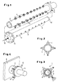
- a after assembly and installation in a pickling not further shown or rinsing tank consisting of nozzle tubes made of nested single tubes 1 comprises an outer spray pipe 2 and an inner pipe 3 according to FIG. 1.
- the spray tube 2 has four, each arranged at an angular distance of 90 ° Spray nozzles 4 having nozzle rows I to IV (see FIGS. 2 and 3).
- the Spray tube 4 is open at one end and closed at the other end. At the closed end it is with an upstream flange 5 provided with the position indicators assigned to each row of nozzles I to IV 6 is provided. With this flange end, the spray tube can be rotated on the container flange 7 one of the container walls 8 is mounted (cf. FIG. 4).
- the inner tube 3 shown in Fig. 1 below is arranged in a row in Embodiment provided as slots 9 openings. While the immersed in the spray tube 2 end of the inner tube 3 with a Cover 10 is closed, there is a flange 11 at its other end, the fixed with the container flange 7 for the outer spray tube 2 opposite Container wall and the pipe flange there for the liquid supply 12 is connected.
- the outer spray tube plugged onto the inner tube 3 encloses 4 the inner tube 3 with a narrow seat sealed by O-rings (cf. Fig. 3).
- the inner tube 3 was previously mounted so that its openings 9 on the Treated goods (not shown) are directed.
- the attached outer spray pipe 4 is then adjusted so that one of the nozzle rows I to IV in a cover position comes with the openings 9 of the inner tube 3, i.e. these are also in curses the spray nozzles 4 of the row of nozzles used, as in FIG. 3 for the row of nozzles III shown.
Landscapes
- Chemical & Material Sciences (AREA)
- Chemical Kinetics & Catalysis (AREA)
- General Chemical & Material Sciences (AREA)
- Engineering & Computer Science (AREA)
- Materials Engineering (AREA)
- Mechanical Engineering (AREA)
- Metallurgy (AREA)
- Organic Chemistry (AREA)
- Cleaning And De-Greasing Of Metallic Materials By Chemical Methods (AREA)
- Nozzles (AREA)
- Cleaning By Liquid Or Steam (AREA)
Abstract
Description
- Fig. 1
- als Einzelheit eines als solchen hinlänglich bekannten Beiz- oder Spülbehälters in perspektivischer Darstellung vor dem Zusammenbau und der Montage zwei in situ ineinanderzusteckende und an gegenüberliegenden Behälterflanschen einzusetzende, komplementäre Rohre;
- Fig. 2
- einen Querschnitt durch das äußere, in Fig. 1 obere, vier Düsenreihen aufweisende Düsenrohr;
- Fig. 3
- einen Querschnitt durch das aus zwei Rohren bestehende Düsenrohr nach dem Aufstecken des äußeren Spritzrohres auf das in Fig. 1 unten gezeigte Innenrohr; und
- Fig. 4
- als Einzelheit der zusammengebauten Düsenrohr-Anordnung deren Anflanschung an eine Behälterwandung, vom Flansch des äußeren Düsenrohres her gesehen.
Claims (4)
- Vorrichtung zum Aufspritzen von Beiz- oder Spülflüssigkeit auf ein langgestrecktes, metallisches Behandlungsgut, insbesondere Metallband, umfassend in einem Beizbehälter oder dergleichen ober- und/oder unterhalb der Transportebene des Behandlungsgutes in den Behälterwandungen angeordnete, mit Spritzdüsen ausgebildete, an eine Flüssigkeitsversorgung angeschlossene zylindrische Spritzrohre, die um ihre Längsachse verstellbar sind,
dadurch gekennzeichnet,
daß das Spritzrohr (2) mindestens zwei voneinander beabstandete Düsenreihen (I bis IV) aufweist und abgedichtet auf einem Innenrohr (3) angeordnet ist, das mit im Längenabstand der Spritzdüsen (4) des äußeren Spritzrohres (2) in einer Reihe vorgesehenen Öffnungen (9) ausgebildet ist und in situ mit diesen Öffnungen (9) auf das Behandlungsgut weisend sowie mit den Spritzdüsen (4) einer Düsenreihe (I bis IV) des äußeren Spritzrohres (2) fluchtend ausgerichtet ist. - Vorrichtung nach Anspruch 1,
dadurch gekennzeichnet,
daß einerseits das äußere Spritzrohr (2) mit einem Behälterflansch (5) drehbar in einer Behälterwandung (8) gelagert ist und andererseits das Innenrohr (3) an der gegenüberliegenden Behälterwandung angeflanscht und mit der Flüssigkeitsversorgung (12) verbunden ist. - Vorrichtung nach Anspruch 1 oder 2,
dadurch gekennzeichnet,
daß die Öffnungen (9) des Innenrohres (3) als Langlöcher ausgebildet sind. - Vorrichtung nach einem der Ansprüche 1 bis 3,
dadurch gekennzeichnet,
daß Spritz- und Innenrohr (2; 3) jeweils mit den Düsenreihen (I bis IV) bzw. der Reihe der Öffnungen (9) zugeordneten Positionsanzeigern (6; 13) versehen sind.
Applications Claiming Priority (2)
| Application Number | Priority Date | Filing Date | Title |
|---|---|---|---|
| DE10003847 | 2000-01-31 | ||
| DE10003847A DE10003847A1 (de) | 2000-01-31 | 2000-01-31 | Vorrichtung zum Aufspritzen von Beiz- oder Spülflüssigkeit auf ein metallisches Behandlungsgut |
Publications (3)
| Publication Number | Publication Date |
|---|---|
| EP1122338A2 true EP1122338A2 (de) | 2001-08-08 |
| EP1122338A3 EP1122338A3 (de) | 2004-01-21 |
| EP1122338B1 EP1122338B1 (de) | 2007-02-28 |
Family
ID=7629132
Family Applications (1)
| Application Number | Title | Priority Date | Filing Date |
|---|---|---|---|
| EP01100533A Expired - Lifetime EP1122338B1 (de) | 2000-01-31 | 2001-01-10 | Vorrichtung zum Aufspritzen von Beiz- oder Spülflüssigkeit auf ein metallisches Behandlungsgut |
Country Status (4)
| Country | Link |
|---|---|
| EP (1) | EP1122338B1 (de) |
| JP (1) | JP2001271187A (de) |
| AT (1) | ATE355403T1 (de) |
| DE (2) | DE10003847A1 (de) |
Cited By (9)
| Publication number | Priority date | Publication date | Assignee | Title |
|---|---|---|---|---|
| WO2004111307A1 (en) * | 2003-06-19 | 2004-12-23 | Resco S.R.L. | Method and apparatus for chemical etching on laminar components |
| CN102873044A (zh) * | 2012-10-24 | 2013-01-16 | 杭州华光焊接新材料股份有限公司 | 铸锭清洗设备 |
| WO2018130799A1 (en) * | 2017-01-13 | 2018-07-19 | Greenbank Technology Limited | Can washer and method |
| CN108773492A (zh) * | 2018-04-08 | 2018-11-09 | 华南农业大学 | 一种喷杆喷头一体化喷洒装置及包括该装置的农用无人机 |
| CN109866999A (zh) * | 2019-02-25 | 2019-06-11 | 珠海格力智能装备有限公司 | 一种清洗装置和具有该清洗装置的容器 |
| CN110355020A (zh) * | 2018-04-11 | 2019-10-22 | 显示器生产服务株式会社 | 流体供应装置及其组装方法和利用该流体供应装置的基板处理系统 |
| CN111617893A (zh) * | 2019-02-27 | 2020-09-04 | 湖南迪宏物联科技有限公司 | 旋转喷头组件、旋转喷头及喷淋系统 |
| EP3970863A1 (de) * | 2020-09-09 | 2022-03-23 | Krones Ag | Reinigungsdüse für eine abfüllanlage und verfahren zum montieren einer reinigungsdüse |
| CN114892179A (zh) * | 2022-04-20 | 2022-08-12 | 嘉兴市磁海无损检测设备制造有限公司 | 一种航空用管材的循环酸洗设备和循环酸洗方法 |
Families Citing this family (12)
| Publication number | Priority date | Publication date | Assignee | Title |
|---|---|---|---|---|
| KR101403253B1 (ko) | 2007-07-23 | 2014-06-02 | 주식회사 포스코 | 다용액 분사장치 |
| DE102008032933A1 (de) | 2008-07-12 | 2010-01-14 | Sms Siemag Aktiengesellschaft | Vorrichtung und Verfahren zum Aufspritzen von Beiz- und/oder Spülflüssigkeit auf ein metallisches Behandlungsgut |
| CN102886324B (zh) * | 2011-07-23 | 2015-05-27 | 佛山市顺德区北滘镇永菱冷却塔厂 | 一种改进的旋转式供水装置喷头 |
| CN103567102A (zh) * | 2012-07-24 | 2014-02-12 | 苏州宏久航空防热材料科技有限公司 | 一种玻璃棉用粘结剂喷洒装置 |
| JP6366328B2 (ja) * | 2014-04-02 | 2018-08-01 | 株式会社中西製作所 | ノズル管ユニットとこれを用いた洗浄装置 |
| CN107937932A (zh) * | 2017-12-12 | 2018-04-20 | 西安泰金工业电化学技术有限公司 | 一种生箔机组水洗喷淋装置 |
| CN109157689B (zh) * | 2018-10-31 | 2021-03-02 | 中国人民解放军陆军特色医学中心 | 一种双腔深静脉血滤管装置 |
| KR102457700B1 (ko) * | 2021-01-21 | 2022-10-24 | 에스케이실트론 주식회사 | 세정제 공급장치 및 상기 세정제 공급장치를 이용한 세정방법 |
| DE202021101330U1 (de) * | 2021-03-16 | 2022-03-21 | Extrutec Gmbh | Profilkühlvorrichtung und Kühlstrang für eine Profilkühlvorrichtung |
| CN113322472A (zh) * | 2021-04-14 | 2021-08-31 | 刘鑫 | 一种五金件除锈装置 |
| CN113600389B (zh) * | 2021-10-08 | 2021-12-10 | 海安苏博机器人科技有限公司 | 一种机器人喷涂生产装置 |
| CN117989809A (zh) * | 2024-03-21 | 2024-05-07 | 东台正德复合材料科技有限公司 | 一种玻璃纤维加工散热机构及冷却系统 |
Family Cites Families (3)
| Publication number | Priority date | Publication date | Assignee | Title |
|---|---|---|---|---|
| DE2627957A1 (de) * | 1976-06-22 | 1978-01-05 | Hammelmann Paul Maschf | Mit duesen ausgeruestetes spritzrohr fuer presswasser zum reinigen von sieben, filtern, filztuechern, saugwalzen o.dgl. |
| BE1003788A5 (fr) * | 1989-03-06 | 1992-06-16 | Cockerill Sambre Sa | Machine decalamineuse. |
| DE4409792C2 (de) * | 1994-03-22 | 1996-02-29 | Eko Stahl Gmbh | Vorrichtung zum Aufspritzen von Beiz-/oder Spülflüssigkeit |
-
2000
- 2000-01-31 DE DE10003847A patent/DE10003847A1/de not_active Withdrawn
-
2001
- 2001-01-10 EP EP01100533A patent/EP1122338B1/de not_active Expired - Lifetime
- 2001-01-10 AT AT01100533T patent/ATE355403T1/de not_active IP Right Cessation
- 2001-01-10 DE DE50112093T patent/DE50112093D1/de not_active Expired - Fee Related
- 2001-01-30 JP JP2001021540A patent/JP2001271187A/ja not_active Withdrawn
Cited By (13)
| Publication number | Priority date | Publication date | Assignee | Title |
|---|---|---|---|---|
| WO2004111307A1 (en) * | 2003-06-19 | 2004-12-23 | Resco S.R.L. | Method and apparatus for chemical etching on laminar components |
| CN102873044A (zh) * | 2012-10-24 | 2013-01-16 | 杭州华光焊接新材料股份有限公司 | 铸锭清洗设备 |
| CN102873044B (zh) * | 2012-10-24 | 2015-05-20 | 杭州华光焊接新材料股份有限公司 | 铸锭清洗设备 |
| WO2018130799A1 (en) * | 2017-01-13 | 2018-07-19 | Greenbank Technology Limited | Can washer and method |
| CN108773492A (zh) * | 2018-04-08 | 2018-11-09 | 华南农业大学 | 一种喷杆喷头一体化喷洒装置及包括该装置的农用无人机 |
| CN108773492B (zh) * | 2018-04-08 | 2020-01-17 | 华南农业大学 | 一种喷杆喷头一体化喷洒装置及包括该装置的农用无人机 |
| CN110355020A (zh) * | 2018-04-11 | 2019-10-22 | 显示器生产服务株式会社 | 流体供应装置及其组装方法和利用该流体供应装置的基板处理系统 |
| CN109866999A (zh) * | 2019-02-25 | 2019-06-11 | 珠海格力智能装备有限公司 | 一种清洗装置和具有该清洗装置的容器 |
| CN111617893A (zh) * | 2019-02-27 | 2020-09-04 | 湖南迪宏物联科技有限公司 | 旋转喷头组件、旋转喷头及喷淋系统 |
| EP3970863A1 (de) * | 2020-09-09 | 2022-03-23 | Krones Ag | Reinigungsdüse für eine abfüllanlage und verfahren zum montieren einer reinigungsdüse |
| CN114226087A (zh) * | 2020-09-09 | 2022-03-25 | 克罗内斯股份公司 | 用于灌装设施的清洁喷嘴和用于安装清洁喷嘴的方法 |
| CN114892179A (zh) * | 2022-04-20 | 2022-08-12 | 嘉兴市磁海无损检测设备制造有限公司 | 一种航空用管材的循环酸洗设备和循环酸洗方法 |
| CN114892179B (zh) * | 2022-04-20 | 2023-08-15 | 嘉兴市磁海无损检测设备制造有限公司 | 一种航空用管材的循环酸洗设备和循环酸洗方法 |
Also Published As
| Publication number | Publication date |
|---|---|
| DE10003847A1 (de) | 2001-08-02 |
| JP2001271187A (ja) | 2001-10-02 |
| EP1122338A3 (de) | 2004-01-21 |
| ATE355403T1 (de) | 2006-03-15 |
| DE50112093D1 (de) | 2007-04-12 |
| EP1122338B1 (de) | 2007-02-28 |
Similar Documents
| Publication | Publication Date | Title |
|---|---|---|
| EP1122338B1 (de) | Vorrichtung zum Aufspritzen von Beiz- oder Spülflüssigkeit auf ein metallisches Behandlungsgut | |
| EP0261469B1 (de) | Vorrichtung zum Reinigen von Gegenständen, die mit Farbe in Berührung gekommen sind | |
| DE19958290B4 (de) | Zylindrischer Großbehälter mit einer Vorrichtung zum Reinigen und/oder Desinfizieren | |
| EP0309743B1 (de) | Rückspülfilter | |
| DE102011053172B4 (de) | Spülvorrichtung zum Reinigen eines von einer Sammelrohrleitung abzweigenden Einzelrohres eines Rohrsystems | |
| DE102019200304A1 (de) | Filtersystem zur Aufreinigung von einem mit Partikeln beladenen Gasstrom und Anordnung zur Aufreinigung von einem mit Partikeln beladenen Gasstrom eines Fluidisierungsapparates mittels eines Filtersystems | |
| EP2867585B1 (de) | Verfahren zum betreiben einer abluftanlage und abluftanlage für eine küche | |
| DE3517751C2 (de) | ||
| DE6921769U (de) | Ausflussmundstueck fuer spritzerarme stroemungen | |
| AT403295B (de) | Vorrichtung zum aufspritzen von beiz-/oder spülflüssigkeit | |
| DE1427912C3 (de) | Einrichtung zum Aufbringen von Kühlflüssigkeit auf ein erhitztes Metallband in einer Walzanlage | |
| EP2138243B1 (de) | Zielstrahlreiniger | |
| DE3623198C2 (de) | ||
| EP2065082A1 (de) | Luft-Reinigungsvorrichtung | |
| DE2039974A1 (de) | Zusatzgeraet zum Anbringen an einem Behandlungsgefaess zum Durchfuehren eines Kontaktverfahrens zwischen festen und fliessfaehigen Medien | |
| DE2639453A1 (de) | Rotations-reinigungsvorrichtung | |
| DE3300352C2 (de) | Vorrichtung zum Abziehen von Filtergranulat | |
| DE202005016872U1 (de) | Auslaufeinrichtung | |
| WO2000035788A1 (de) | Anlage zum schmieren, reinigen und/oder desinfizieren von stetigförderern | |
| DE474197C (de) | Wasserverteilungsvorrichtung fuer Geschirrspuelmaschinen | |
| WO2018234036A1 (de) | Anschlusskopf und ventilknoten | |
| DE4302867C2 (de) | Vorrichtung zur Mischung und Lösung eines Gases in einer Flüssigkeit | |
| DE10159443B4 (de) | Vorrichtung zum Wechseln von Düsen | |
| DE331858C (de) | Vorrichtung zum Reinigen von Schlauch- und Roehrenleitungen | |
| DE2535089A1 (de) | Vorrichtung zum zerstaeuben von fluessigkeiten und verwendung dieser vorrichtung |
Legal Events
| Date | Code | Title | Description |
|---|---|---|---|
| PUAI | Public reference made under article 153(3) epc to a published international application that has entered the european phase |
Free format text: ORIGINAL CODE: 0009012 |
|
| 17P | Request for examination filed |
Effective date: 20010131 |
|
| AK | Designated contracting states |
Kind code of ref document: A2 Designated state(s): AT BE CH CY DE DK ES FI FR GB GR IE IT LI LU MC NL PT SE TR |
|
| AX | Request for extension of the european patent |
Free format text: AL;LT;LV;MK;RO;SI |
|
| PUAL | Search report despatched |
Free format text: ORIGINAL CODE: 0009013 |
|
| AK | Designated contracting states |
Kind code of ref document: A3 Designated state(s): AT BE CH CY DE DK ES FI FR GB GR IE IT LI LU MC NL PT SE TR |
|
| AX | Request for extension of the european patent |
Extension state: AL LT LV MK RO SI |
|
| RIC1 | Information provided on ipc code assigned before grant |
Ipc: 7C 23G 3/02 A Ipc: 7B 05B 1/16 B |
|
| AKX | Designation fees paid |
Designated state(s): AT BE CH CY DE DK ES FI FR GB GR IE IT LI LU MC NL PT SE TR |
|
| 17Q | First examination report despatched |
Effective date: 20050418 |
|
| GRAP | Despatch of communication of intention to grant a patent |
Free format text: ORIGINAL CODE: EPIDOSNIGR1 |
|
| GRAS | Grant fee paid |
Free format text: ORIGINAL CODE: EPIDOSNIGR3 |
|
| GRAA | (expected) grant |
Free format text: ORIGINAL CODE: 0009210 |
|
| AK | Designated contracting states |
Kind code of ref document: B1 Designated state(s): AT BE CH CY DE DK ES FI FR GB GR IE IT LI LU MC NL PT SE TR |
|
| PG25 | Lapsed in a contracting state [announced via postgrant information from national office to epo] |
Ref country code: FI Free format text: LAPSE BECAUSE OF FAILURE TO SUBMIT A TRANSLATION OF THE DESCRIPTION OR TO PAY THE FEE WITHIN THE PRESCRIBED TIME-LIMIT Effective date: 20070228 Ref country code: DK Free format text: LAPSE BECAUSE OF FAILURE TO SUBMIT A TRANSLATION OF THE DESCRIPTION OR TO PAY THE FEE WITHIN THE PRESCRIBED TIME-LIMIT Effective date: 20070228 Ref country code: NL Free format text: LAPSE BECAUSE OF FAILURE TO SUBMIT A TRANSLATION OF THE DESCRIPTION OR TO PAY THE FEE WITHIN THE PRESCRIBED TIME-LIMIT Effective date: 20070228 Ref country code: IE Free format text: LAPSE BECAUSE OF FAILURE TO SUBMIT A TRANSLATION OF THE DESCRIPTION OR TO PAY THE FEE WITHIN THE PRESCRIBED TIME-LIMIT Effective date: 20070228 |
|
| REG | Reference to a national code |
Ref country code: GB Ref legal event code: FG4D Free format text: NOT ENGLISH |
|
| REG | Reference to a national code |
Ref country code: CH Ref legal event code: EP |
|
| REF | Corresponds to: |
Ref document number: 50112093 Country of ref document: DE Date of ref document: 20070412 Kind code of ref document: P |
|
| REG | Reference to a national code |
Ref country code: IE Ref legal event code: FG4D Free format text: LANGUAGE OF EP DOCUMENT: GERMAN |
|
| PG25 | Lapsed in a contracting state [announced via postgrant information from national office to epo] |
Ref country code: SE Free format text: LAPSE BECAUSE OF FAILURE TO SUBMIT A TRANSLATION OF THE DESCRIPTION OR TO PAY THE FEE WITHIN THE PRESCRIBED TIME-LIMIT Effective date: 20070531 |
|
| PG25 | Lapsed in a contracting state [announced via postgrant information from national office to epo] |
Ref country code: ES Free format text: LAPSE BECAUSE OF FAILURE TO SUBMIT A TRANSLATION OF THE DESCRIPTION OR TO PAY THE FEE WITHIN THE PRESCRIBED TIME-LIMIT Effective date: 20070608 |
|
| PG25 | Lapsed in a contracting state [announced via postgrant information from national office to epo] |
Ref country code: PT Free format text: LAPSE BECAUSE OF FAILURE TO SUBMIT A TRANSLATION OF THE DESCRIPTION OR TO PAY THE FEE WITHIN THE PRESCRIBED TIME-LIMIT Effective date: 20070730 |
|
| NLV1 | Nl: lapsed or annulled due to failure to fulfill the requirements of art. 29p and 29m of the patents act | ||
| GBV | Gb: ep patent (uk) treated as always having been void in accordance with gb section 77(7)/1977 [no translation filed] |
Effective date: 20070228 |
|
| REG | Reference to a national code |
Ref country code: IE Ref legal event code: FD4D |
|
| EN | Fr: translation not filed | ||
| PG25 | Lapsed in a contracting state [announced via postgrant information from national office to epo] |
Ref country code: GB Free format text: LAPSE BECAUSE OF FAILURE TO SUBMIT A TRANSLATION OF THE DESCRIPTION OR TO PAY THE FEE WITHIN THE PRESCRIBED TIME-LIMIT Effective date: 20070228 |
|
| PLBE | No opposition filed within time limit |
Free format text: ORIGINAL CODE: 0009261 |
|
| STAA | Information on the status of an ep patent application or granted ep patent |
Free format text: STATUS: NO OPPOSITION FILED WITHIN TIME LIMIT |
|
| 26N | No opposition filed |
Effective date: 20071129 |
|
| PG25 | Lapsed in a contracting state [announced via postgrant information from national office to epo] |
Ref country code: FR Free format text: LAPSE BECAUSE OF FAILURE TO SUBMIT A TRANSLATION OF THE DESCRIPTION OR TO PAY THE FEE WITHIN THE PRESCRIBED TIME-LIMIT Effective date: 20071019 Ref country code: IT Free format text: LAPSE BECAUSE OF FAILURE TO SUBMIT A TRANSLATION OF THE DESCRIPTION OR TO PAY THE FEE WITHIN THE PRESCRIBED TIME-LIMIT Effective date: 20070228 Ref country code: GR Free format text: LAPSE BECAUSE OF FAILURE TO SUBMIT A TRANSLATION OF THE DESCRIPTION OR TO PAY THE FEE WITHIN THE PRESCRIBED TIME-LIMIT Effective date: 20070529 |
|
| BERE | Be: lapsed |
Owner name: MS DEMAG AG Effective date: 20080131 |
|
| PG25 | Lapsed in a contracting state [announced via postgrant information from national office to epo] |
Ref country code: MC Free format text: LAPSE BECAUSE OF NON-PAYMENT OF DUE FEES Effective date: 20080131 |
|
| REG | Reference to a national code |
Ref country code: CH Ref legal event code: PL |
|
| PG25 | Lapsed in a contracting state [announced via postgrant information from national office to epo] |
Ref country code: DE Free format text: LAPSE BECAUSE OF NON-PAYMENT OF DUE FEES Effective date: 20080801 Ref country code: LI Free format text: LAPSE BECAUSE OF NON-PAYMENT OF DUE FEES Effective date: 20080131 Ref country code: CH Free format text: LAPSE BECAUSE OF NON-PAYMENT OF DUE FEES Effective date: 20080131 |
|
| PG25 | Lapsed in a contracting state [announced via postgrant information from national office to epo] |
Ref country code: FR Free format text: LAPSE BECAUSE OF FAILURE TO SUBMIT A TRANSLATION OF THE DESCRIPTION OR TO PAY THE FEE WITHIN THE PRESCRIBED TIME-LIMIT Effective date: 20070228 |
|
| PG25 | Lapsed in a contracting state [announced via postgrant information from national office to epo] |
Ref country code: BE Free format text: LAPSE BECAUSE OF NON-PAYMENT OF DUE FEES Effective date: 20080131 |
|
| PG25 | Lapsed in a contracting state [announced via postgrant information from national office to epo] |
Ref country code: AT Free format text: LAPSE BECAUSE OF NON-PAYMENT OF DUE FEES Effective date: 20080110 |
|
| PG25 | Lapsed in a contracting state [announced via postgrant information from national office to epo] |
Ref country code: CY Free format text: LAPSE BECAUSE OF FAILURE TO SUBMIT A TRANSLATION OF THE DESCRIPTION OR TO PAY THE FEE WITHIN THE PRESCRIBED TIME-LIMIT Effective date: 20070228 |
|
| PG25 | Lapsed in a contracting state [announced via postgrant information from national office to epo] |
Ref country code: LU Free format text: LAPSE BECAUSE OF NON-PAYMENT OF DUE FEES Effective date: 20080110 |
|
| PG25 | Lapsed in a contracting state [announced via postgrant information from national office to epo] |
Ref country code: TR Free format text: LAPSE BECAUSE OF FAILURE TO SUBMIT A TRANSLATION OF THE DESCRIPTION OR TO PAY THE FEE WITHIN THE PRESCRIBED TIME-LIMIT Effective date: 20070228 |