EP1122393B1 - Blend- und/oder Flügelrahmen für Fenster - Google Patents
Blend- und/oder Flügelrahmen für Fenster Download PDFInfo
- Publication number
- EP1122393B1 EP1122393B1 EP01200281A EP01200281A EP1122393B1 EP 1122393 B1 EP1122393 B1 EP 1122393B1 EP 01200281 A EP01200281 A EP 01200281A EP 01200281 A EP01200281 A EP 01200281A EP 1122393 B1 EP1122393 B1 EP 1122393B1
- Authority
- EP
- European Patent Office
- Prior art keywords
- appendix
- profile
- frame
- wing
- integral
- Prior art date
- Legal status (The legal status is an assumption and is not a legal conclusion. Google has not performed a legal analysis and makes no representation as to the accuracy of the status listed.)
- Expired - Lifetime
Links
- 239000004033 plastic Substances 0.000 claims abstract description 13
- 229920003023 plastic Polymers 0.000 claims abstract description 13
- 229910052751 metal Inorganic materials 0.000 claims abstract description 11
- 239000002184 metal Substances 0.000 claims abstract description 11
- 238000009434 installation Methods 0.000 claims description 2
- 239000004411 aluminium Substances 0.000 description 6
- 229910052782 aluminium Inorganic materials 0.000 description 6
- XAGFODPZIPBFFR-UHFFFAOYSA-N aluminium Chemical compound [Al] XAGFODPZIPBFFR-UHFFFAOYSA-N 0.000 description 6
- 239000011521 glass Substances 0.000 description 4
- 238000009413 insulation Methods 0.000 description 4
- 230000004888 barrier function Effects 0.000 description 3
- 230000037431 insertion Effects 0.000 description 2
- 238000003780 insertion Methods 0.000 description 2
- 239000011810 insulating material Substances 0.000 description 2
- 239000000203 mixture Substances 0.000 description 2
- 239000004743 Polypropylene Substances 0.000 description 1
- 230000005540 biological transmission Effects 0.000 description 1
- 230000015572 biosynthetic process Effects 0.000 description 1
- 239000003086 colorant Substances 0.000 description 1
- 230000005494 condensation Effects 0.000 description 1
- 238000009833 condensation Methods 0.000 description 1
- 230000001419 dependent effect Effects 0.000 description 1
- 238000005516 engineering process Methods 0.000 description 1
- 229910001234 light alloy Inorganic materials 0.000 description 1
- 238000003754 machining Methods 0.000 description 1
- 239000000463 material Substances 0.000 description 1
- 238000005192 partition Methods 0.000 description 1
- -1 polypropylene Polymers 0.000 description 1
- 229920001155 polypropylene Polymers 0.000 description 1
- 229920002635 polyurethane Polymers 0.000 description 1
- 239000004814 polyurethane Substances 0.000 description 1
- 229920000915 polyvinyl chloride Polymers 0.000 description 1
- 239000004800 polyvinyl chloride Substances 0.000 description 1
- 230000002265 prevention Effects 0.000 description 1
- 238000004080 punching Methods 0.000 description 1
- 230000002787 reinforcement Effects 0.000 description 1
- 238000007789 sealing Methods 0.000 description 1
- 238000009423 ventilation Methods 0.000 description 1
- XLYOFNOQVPJJNP-UHFFFAOYSA-N water Substances O XLYOFNOQVPJJNP-UHFFFAOYSA-N 0.000 description 1
Images


Classifications
-
- E—FIXED CONSTRUCTIONS
- E06—DOORS, WINDOWS, SHUTTERS, OR ROLLER BLINDS IN GENERAL; LADDERS
- E06B—FIXED OR MOVABLE CLOSURES FOR OPENINGS IN BUILDINGS, VEHICLES, FENCES OR LIKE ENCLOSURES IN GENERAL, e.g. DOORS, WINDOWS, BLINDS, GATES
- E06B3/00—Window sashes, door leaves, or like elements for closing wall or like openings; Layout of fixed or moving closures, e.g. windows in wall or like openings; Features of rigidly-mounted outer frames relating to the mounting of wing frames
- E06B3/30—Coverings, e.g. protecting against weather, for decorative purposes
- E06B3/301—Coverings, e.g. protecting against weather, for decorative purposes consisting of prefabricated profiled members or glass
- E06B3/305—Covering metal frames with plastic or metal profiled members
-
- E—FIXED CONSTRUCTIONS
- E06—DOORS, WINDOWS, SHUTTERS, OR ROLLER BLINDS IN GENERAL; LADDERS
- E06B—FIXED OR MOVABLE CLOSURES FOR OPENINGS IN BUILDINGS, VEHICLES, FENCES OR LIKE ENCLOSURES IN GENERAL, e.g. DOORS, WINDOWS, BLINDS, GATES
- E06B3/00—Window sashes, door leaves, or like elements for closing wall or like openings; Layout of fixed or moving closures, e.g. windows in wall or like openings; Features of rigidly-mounted outer frames relating to the mounting of wing frames
- E06B3/04—Wing frames not characterised by the manner of movement
- E06B3/263—Frames with special provision for insulation
- E06B3/26341—Frames with special provision for insulation comprising only one metal frame member combined with an insulating frame member
-
- E—FIXED CONSTRUCTIONS
- E06—DOORS, WINDOWS, SHUTTERS, OR ROLLER BLINDS IN GENERAL; LADDERS
- E06B—FIXED OR MOVABLE CLOSURES FOR OPENINGS IN BUILDINGS, VEHICLES, FENCES OR LIKE ENCLOSURES IN GENERAL, e.g. DOORS, WINDOWS, BLINDS, GATES
- E06B3/00—Window sashes, door leaves, or like elements for closing wall or like openings; Layout of fixed or moving closures, e.g. windows in wall or like openings; Features of rigidly-mounted outer frames relating to the mounting of wing frames
- E06B3/04—Wing frames not characterised by the manner of movement
- E06B3/263—Frames with special provision for insulation
- E06B3/2632—Frames with special provision for insulation with arrangements reducing the heat transmission, other than an interruption in a metal section
- E06B2003/26332—Arrangements reducing the heat transfer in the glazing rabbet or the space between the wing and the casing frame
Definitions
- the present invention refers to a structure for wing and/or frame of a window frame.
- a window frame is an element designed to close an aperture of an external shell (walls or roof) or of internal partition walls of a building.
- window frame will be used with particular reference to elements of the first type, i.e. designed to close the apertures of the external shell of buildings, of the type made of metal, usually aluminium, even though the inventive concepts that will be illustrated naturally apply to all window frames.
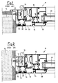
- figures 1 and 2 show two typical examples of conventional window frames 11, built using known technology.
- the window frames 11 comprise a frame 12, integral with a wall 14, to which a wing 18 provided with glazed surface 20 is hinged in 16.
- the frame 12 consists of two distinct portions.
- the portion 22 is provided with seats 26 in which first ends of bars 28, in insulating material, are fixed.
- Second ends of the bars 28 are inserted in seats 30 of an outer portion 32 of the frame 12, also made of metal.
- the internal portion 22 and the external portion 32 of the frame 12 are made of aluminium, while the bars 28 are usually made of plastic.
- the structure of the wing 18 is the same as that of the frame 12.
- the wing 18 comprises an internal portion 34 in aluminium connected via plastic bars 36 to an external portion 38 of the same wing 18, again made of aluminium.
- the function of the bars 28, 36 is to obstruct heat transmission, therefore acting as a thermal barrier.
- window frames of the type described are difficult to machine and, above all, to assemble.
- the thermal barrier bars 28, 36 have to be inserted between the respective profiles.
- expensive assembly machines are necessary that also limit the composition versatility of the frame profiles.
- CH330031 refers to a cooling-bridge interruption and prevention of the condensation on a light alloy window framework through plastic strips with spring-actuated lock attached to the same.
- GB-A-2106579 refers to a frame member comprising a metal element having a thermal insulating covering, including an outer rigid shell defining an interior cavity into which has been extruded a foamed plastic material.
- the frame member and the covering have longitudinally extending formation which secure the covering and the metal element one to another.
- the object of the present invention is, therefore, to eliminate the above technical problems by producing a structure for wing and/or frame of a window frame that can be machined and assembled with extreme simplicity.
- the structure according to the invention does not require expensive assembly machines to join one internal portion of the frame or wing to an external portion.
- Another object of the invention is to produce a window frame structure that is extremely sturdy and, at the same time, very lightweight.
- a further object of the invention is to produce a window frame structure that permits considerable versatility of composition of the frame or wing profiles.
- the structure of a window frame permits decorative motifs to be stamped on the frame and on the wing simply and cheaply and, in particular, it is possible to produce window frames in two colours. Moreover, it is also possible to provide ventilation of the glass and create water drains not exposed to view without the insertion of weatherproof guards.
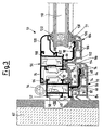
- a structure for wing and/or frame of a window frame is shown, indicated overall by reference number 51.
- the structure 51 comprises a first frame profile 52 with tubular structure.
- a first wing profile 56 is hinged to the first frame profile 52 by means of hinges 54 fixed to its first wall.
- the first frame profile 52 is provided with a pair of appendixes that form seats 58 in which rawl plugs 60 are locked.
- the rawl plugs 60 are in their turn fixed, by means of screws, to a wall 62.
- a square appendix 64 extends from a third wall, opposite the first one fitted with the hinges 54.
- the appendix 64 has a first portion integral with the first frame profile 52 and provided with a relief element 66 while a second portion of the appendix 64 is bent square in order not to interfere with the seats 58.
- a plain connector is provided between the first and second portion of the appendix 64.
- a terminal portion not in line with said second portion in order to further ensure that it does not interfere with the first frame profile 52 is integral with the second portion of the appendix 64.
- a notch 68 is also positioned corresponding to the end portion, and the free end of the appendix 64 is rounded.
- the appendix 64 is necessary to fit a second frame profile 70, also with the help of another square appendix 72, which extends from a corner positioned between the second and third wall of the first frame profile 52.
- the second frame profile 70 features a tubular structure that forms one or more air chambers 74.
- One end of the second frame profile 70 protrudes and contains a rounded groove 76 in which the rounded free end of the appendix 64 is inserted as a guide element.
- a groove 77 is also provided, which can be used as a seal seat.
- a flat element 78 protrudes with free end enlarged and blocked against the protruding element 66, as engaged elements.
- a further two flat elements 80, 82 extend from the flat element 78.
- the element 80 is fixed corresponding to the free end of the element 78 and has a back portion abutting on the appendix 72.
- the appendix 82 blocks a seal 84 also with the help of a protruding edge 86 of the second frame profile 70.
- a thermal insulating element 88 is positioned on the other side of the appendix 64.
- a first end of the element 88 extends well beyond the second end. Said first end is provided with a relief element inserted inside the notch 68.
- a second end of the element 88 is also provided with a relief element which engages with a square appendix 90, which extends from a corner located between the third wall and a fourth wall of the first frame profile 52.
- An end portion of the second end of the element 88 is bent in order to form a support for a seal element 92.
- element 88 Another important function of the element 88 is to act as a block for profile 70 (or for profile 104 which will be illustrated in further detail below), preventing them coming out of their installation position by means of reciprocal contact of parts 180 and 181.
- the first wing profile 56 which is fixed to the hinge 54, features a rectangular-shaped tubular structure.
- a portion 94 fitted at the end with a seal 96 abutting on the first frame profile 52 extends from a corner between a first wall facing the inside of an area limited by the window frame and a second wall facing the first frame profile 52.
- a third wall opposite the first one, is fitted with an appendix 98 identical to the appendix 64 of the first frame profile 52 and therefore the details of this appendix are indicated with the same numbers as those already used for appendix 64. From the two corners forming said third wall, two appendixes 100, 102 extend which provide for support of a second wing profile 104 and a reinforcement element the same as element 88 and not shown for the sake of simplicity.
- the second wing profile 104 made of plastic, is similar to the second frame profile 70 and some numbers are therefore repeated for the sake of simplicity.
- the second wing profile 104 features a tubular structure forming air chambers 106 inside. Furthermore, a portion with groove 76 that locks on the end section of appendix 98, as an engaged element, protrudes from the second wing profile 104. Said protruding portion is fitted with a seal 108 which locks on a glass panel or other element 110 supported by the first wing profile 56.
- the second wing profile 104 features a flat element 112 locked on the relief element 66 of the first wing profile 56, like engaged elements, as already indicated for the second frame profile 70. Furthermore, a flat element 114 that protrudes from the element 112 abuts on the seal 92. From the flat element 112, an element 116 extends which, when the wing is closed, is facing but not in contact with the second frame profile 70.
- a fourth wall adjacent to the first and third, is fitted with the hooking elements 118 to which a profile 120, fitted at its end with a seal 122 positioned against element 110, can be coupled.
- the first frame profile 52 and the first wing profile 56 are both made of aluminium, which guarantees sturdiness and at the same time lightness.
- the first frame profile 70 and the second wing profile 104 are made of insulating material such as PVC, polypropylene, polyurethane or other, to ensure heat insulation with easy machining.
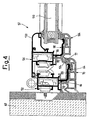
- FIG 4 A second embodiment of the window frame structure, according to the present invention, is shown in figure 4, where identical or similar elements are indicated with the same numbers as those of the first embodiment described above.
- first frame profile 52, the second frame profile 70 and the first wing profile 56 are the same as those already described, while the second wing profile 104 differs from the one of the first embodiment shown in figure 3 and is identical to the second frame profile 70.
- a seal 124 is locked inside the groove 77 of the second frame profile 70.
- the seal abuts against the appendix 82 of the second wing profile 104 and guarantees the window frame seal.
- FIGS 5 to 8 show details of the frames of the structure according to the invention where elements identical or similar to those already described are indicated by the same or similar numbers.
- Figure 5 shows a frame positioned inside the opening of the window frame which is the one already described in figures 3 and 4.
- Figure 6 shows an example of external ledge frame.
- the first frame profile 52 is identical to the one of figure 5 while the second frame profile features a portion identical to the second frame profile of figure 5 and a further portion that makes its external profile symmetrical with a central axis (not shown).
- Figure 7 shows an example of internal ledge frame.
- the first frame profile is similar to the frame of figure 5 but features an elongated portion 126 which extends in the opposite direction from the appendix 64 and is provided with a seat 128 for a seal.
- the second frame profile 70 is identical to the one shown in figure 5.
- Figure 8 shows an example of chair-shaped frame.
- first frame profile 52 is identical to the one shown in figure 7 while the second frame profile 70 is identical to the one shown in figure 6.
- Figures 9 and 10 show some details of the wings of the structure according to the invention, indicating, with identical or similar numbers, elements identical or similar to the ones already described.
- Figure 9 shows a wing for seal system with open joint seal. Said wing is identical to the one shown in figure 3.
- Figure 10 shows a wing for a seal system with abutment seal. Said wing is identical to the one shown in figure 4.
- Figure 11 shows a profile for flat central panel point. This features a structure identical to that of the frame or wing already described and comprises an internal element 130 in aluminium and an external element in plastic 132.
- the internal element 130 has a tubular structure and features at one end an element 134 shaped similarly to the appendix 98 so that the external element 132 can be locked on it.
- the element 134 features a free portion 136 identical to that of the appendix 98, the latter being extended with a square element 138 fitted with a protruding element 140.
- the element 132 in its turn, features a structure similar to that of the second frame profile, shown in figure 6.
- the element 132 has a tubular structure with a portion protruding at one end provided with a seat 142 identical to seat 77.
- the other end is also protruding and features an abutment element 144.
- a further flat element 146 with enlarged end hooked in the protruding element 140 is fixed on the external element 132.
- Assembly of the second frame profile 70 on the first frame profile 52 and of the second wing profile 104 on the first wing profile 56 is very simple and quick and is performed basically as follows.
- the second frame profile 70 is rested on the appendix 64 and snap-locked onto the latter.
- the second wing profile 104 is rested on the appendix 98 and snap-locked onto the latter.
- thermal insulation elements 88 are locked in the same way.
- the locking and thermal barrier functions of the profiles 70 and 104 are also ensured by hooking of the end portion of the flat element 78 with the relief element 66 and by contact of the flat element 80 (p 114) with the flat element 100.
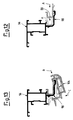
- Figures 12 and 13 show, for example, insertion of the thermal insulation element 88 and the second wing profile 104 on the first wing profile 56, referring to the wing in the first embodiment described.
- the window frames are made with "European chamber". In this way it is in fact possible to create any type of existing ledge window frame and purchase the accessories at very reasonable prices (since almost all manufacturers of accessories and sub-contractors make them); this avoids procurement from one single exclusive supplier.
- the structure for a wing and/or frame of a window frame is particularly advantageous. Furthermore, the different types of frame profiles and the different types of wing profiles are interchangeable in order to meet many different needs without having to produce an excessive number of products.
Landscapes
- Engineering & Computer Science (AREA)
- Civil Engineering (AREA)
- Structural Engineering (AREA)
- Vehicle Interior And Exterior Ornaments, Soundproofing, And Insulation (AREA)
- Securing Of Glass Panes Or The Like (AREA)
- Liquid Crystal (AREA)
- Specific Sealing Or Ventilating Devices For Doors And Windows (AREA)
- Hinges (AREA)
- Window Of Vehicle (AREA)
Claims (11)
- Aufbau (51) für einen Flügel und Rahmen eines Fensterrahmens, umfassend für die Produktion des oben erwähnten Flügels und Rahmens ein erstes Rahmenprofil (52) und ein erstes Flügelprofil (56), die aus Metall hergestellt sind, ein zweites Rahmenprofil (70) und ein zweites Flügelprofil (104), die aus Kunststoff hergestellt sind, und ein oder zwei Isolierungselemente (88), wobei das erste Rahmenprofil (52) an dem zweiten Rahmenprofil (70) mittels erster Eingriffselemente (64, 66, 76, 78) durch Schnappwirkung gesichert ist und das erste Flügelprofil (56) an dem zweiten Flügelprofil (104) mittels zweiter Eingriffselemente (66, 76, 98, 112) durch Schnappwirkung gesichert ist, die ersten Eingriffselemente (64, 66, 76, 78) einen ersten Ansatz (64), der einteilig mit dem ersten Rahmenprofil (52) ist, umfassen, an dem das zweite Rahmenprofil (70) gesichert ist, und wobei der Ansatz (64) in zumindest eine Nut (76) des zweiten Rahmenprofils (70) eingesetzt ist, die zweiten Eingriffselemente (66, 76, 98, 112) einen zweiten Ansatz (98), der einteilig mit dem ersten Flügelprofil (56) ist, umfassen, an dem das zweite Flügelprofil (104) gesichert ist, und wobei der Ansatz (98) in zumindest eine Nut (76) des zweiten Flügelprofils (104) eingesetzt ist, dadurch gekennzeichnet, dass:- der erste und zweite Ansatz (64, 98) im Wesentlichen eine L-Form besitzen, wobei der freie Abschnitt parallel zu der Ebene des Rahmens verläuft, das zweite Rahmenprofil (70) die Außenfläche des ersten Ansatzes (64) bedeckt und das zweite Flügelprofil (104) die Außenfläche des zweiten Ansatzes (98) bedeckt,- der erste und zweite Ansatz (64, 98) beide nahe dem Ende ihres freien Abschnittes zumindest eine Kerbe (68) aufweisen,- ein dritter Ansatz (90) einteilig mit dem ersten Rahmenprofil (52) ausgebildet ist und ein vierter Ansatz (102) einteilig mit dem ersten Flügelprofil (56) ausgebildet ist,- das Isolierungselement (88) oder eines der Isolierungselemente die Innenfläche des ersten (64) oder zweiten Ansatzes (98) durch Einsetzen desselben in die jeweilige Kerbe (68) und Sichern desselben an dem dritten (90) bzw. vierten Ansatz (102) bedecken kann, und- die zweiten Rahmen- und Flügelprofile (70, 104) einen Rohrförmigen Aufbau aufweisen, der einen Satz von Luftkammern (74, 106) bildet.
- Aufbau (51) nach Anspruch 1, dadurch gekennzeichnet, dass die Ansätze (64, 98) grundsätzlich quadratisch sind.
- Aufbau (51) nach Anspruch 2, dadurch gekennzeichnet, dass ein Anschlussabschnitt der Ansätze (64, 98) nicht in Ausrichtung mit den gleichen Ansätzen (64, 98) ist, um sich nicht mit dem ersten Rahmenprofil (52) und dem ersten Flügelprofil (56) zu überlagern.
- Aufbau (51) nach Anspruch 3, dadurch gekennzeichnet, dass das Element (88) als eine Verriegelung für das zweite Rahmenprofil (70) oder für das zweite Flügelprofil (104) wirkt, wodurch mittels eines gegenseitigen Kontakts der Teile (180, 181) verhindert wird, dass diese aus ihrer Montageposition kommen.
- Aufbau (51) nach Anspruch 1, dadurch gekennzeichnet, dass die freien Enden der Ansätze (64, 98) und die Nuten (76) gerundet sind.
- Aufbau (51) nach Anspruch 1, dadurch gekennzeichnet, dass entsprechend einem vorragenden Ende des zweiten Rahmenprofils (70) und des zweiten Flügelprofils (104) zumindest eine Nut (77) vorgesehen ist, die als ein Dichtungssitz verwendet werden kann.
- Aufbau (51) nach Anspruch 1, dadurch gekennzeichnet, dass die ersten in Eingriff stehenden Elemente (64, 66, 76, 78) und die zweiten in Eingriff stehenden Elemente (66, 76, 98, 112) zumindest ein flaches Element (78, 112) umfassen, das von einem Ende des zweiten Rahmenprofils (70) und des zweiten Flügelprofils (104) wegführt, wobei das flache Element (78, 112) ein freies Ende aufweist, das vergrößert ist und an einem vorragenden Element (66) der Ansätze (64, 98) gesichert ist.
- Aufbau (51) nach Anspruch 7, dadurch gekennzeichnet, dass von dem flachen Element (78, 112) zumindest ein anderes flaches Element (80, 114) wegführt, das an einen Ansatz (72, 100) des ersten Rahmenprofils (52) und des zweiten Flügelprofils (56) anstößt.
- Rahmen, der ein Teil eines Aufbaus eines Fensterrahmens bildet, mit einem ersten Rahmenprofil (52), das aus Metall besteht, einem zweiten Rahmenprofil (70), das aus Kunststoff besteht, und einem Isolierungselement (88), wobei das erste Rahmenprofil (52) über erste Eingriffselemente (64, 66, 76, 78) durch Schnappwirkung gesichert ist, die ersten Eingriffselemente (64, 66, 76, 78) einen Ansatz (64), der einteilig mit dem ersten Rahmenprofil (52) ist, umfassen, an dem das zweite Rahmenprofil (70) gesichert ist, und wobei der Ansatz (64) in zumindest eine Nut (76) des zweiten Rahmenprofils (70) eingesetzt ist, dadurch gekennzeichnet, dass:- der Ansatz (64) im Wesentlichen eine L-Form besitzt, wobei der freie Abschnitt parallel zu der Ebene des Rahmens ist und das zweite Rahmenprofil (104) die Außenfläche des Ansatzes (64) bedeckt,- der Ansatz (64) nahe seinem Ende seines freien Abschnittes zumindest eine Kerbe (68) aufweist,- ein anderer Ansatz (90) einteilig mit dem ersten Rahmenprofil (52) ausgebildet ist,- das Isolierungselement (88) die Innenfläche des Ansatzes (64) durch Einsetzen desselben in die jeweilige Kerbe (68) und Sichern desselben an dem anderen Ansatz (90) bedecken kann, und- das zweite Rahmenprofil (70) einen rohrförmigen Aufbau besitzt, der einen Satz von Luftkammern (74) bildet.
- Flügel, der einen Teil eines Aufbaus (51) eines Fensterrahmens bildet, mit einem ersten Flügelprofil (56), das aus Metall besteht, einem zweiten Flügelprofil (104), das aus Kunststoff besteht, und einem Isolierungselement (88), wobei das erste Flügelprofil (56) an dem zweiten Flügelprofil (104) über Eingriffselemente (66, 76, 98, 112) durch Schnappwirkung gesichert ist, die zweiten Eingriffselemente einen Ansatz (98), der einteilig mit dem ersten Flügelprofil (56) ist, umfassen, an dem das zweite Flügelprofil (104) gesichert ist, und wobei der Ansatz (98) in zumindest eine Nut (76) des zweiten Flügelprofils (104) eingesetzt ist, dadurch gekennzeichnet, dass:- der Ansatz (98) im Wesentlichen eine L-Form besitzt, wobei der freie Abschnitt parallel zu der Ebene des Flügels ist und das zweite Flügelprofil (104) die Außenfläche des Ansatzes (98) bedeckt,- der Ansatz (98) nahe seinem Ende seines freien Abschnittes zumindest eine Kerbe (68) aufweist,- ein anderer Ansatz (102) einteilig mit dem ersten Flügelprofil (56) ausgebildet ist,- das Isolierungselement (88) die Innenfläche des Ansatzes (64) durch Einsetzen desselben in die jeweilige Kerbe (68) und Sichern desselben an dem anderen Ansatz (102), der einteilig mit dem ersten Flügelprofil (56) ist, bedecken kann, und- das zweite Flügelprofil (104) einen rohrförmigen Aufbau aufweist, der einen Satz von Luftkammer (106) bildet.
- Inversionsprofil, das einen Teil eines Aufbaus (51) eines Fensterrahmens bildet, mit zumindest einem Innenelement (130), das aus Metall besteht, einem Außenelement (132), das aus Kunststoff besteht, und einem Isolierungselement (88), wobei das zumindest eine Innenelement (130) an dem Außenelement (132) über erste Eingriffselemente durch Schnappwirkung gesichert ist, die ersten Eingriffselemente einen Ansatz (134), der einteilig mit dem zumindest einen Innenelement (130) ist, umfassen, an dem das Außenelement (132) gesichert ist, und wobei der Ansatz in zumindest eine Nut des Außenelements (132) eingesetzt ist, dadurch gekennzeichnet, dass:- der Ansatz im Wesentlichen eine L-Form besitzt, wobei der freie Abschnitt parallel zu der Ebene des Flügels angeordnet ist und das Außenelement (132) die Außenfläche des zumindest einen Innenelements (130) bedeckt,- der Ansatz nahe seinem Ende seines freien Abschnittes zumindest eine Kerbe aufweist,- ein anderer Ansatz (90) einteilig mit dem zumindest einen Innenelement (130) ausgebildet ist,- das Isolierungselement (88) die Innenfläche des Ansatzes durch Einsetzen desselben in die jeweilige Kerbe und Sichern desselben an dem anderen Ansatz (90), der einteilig mit dem zumindest einen Innenelement (130) ist, bedecken kann, und- das Außenelement (132) einen rohrförmigen Aufbau aufweist, der einen Satz von Luftkammern bildet.
Applications Claiming Priority (2)
| Application Number | Priority Date | Filing Date | Title |
|---|---|---|---|
| ITMI200181 | 2000-02-04 | ||
| IT2000MI000181A IT1316342B1 (it) | 2000-02-04 | 2000-02-04 | Struttura per anta e/o telaio di un serramento |
Publications (3)
| Publication Number | Publication Date |
|---|---|
| EP1122393A2 EP1122393A2 (de) | 2001-08-08 |
| EP1122393A3 EP1122393A3 (de) | 2002-06-26 |
| EP1122393B1 true EP1122393B1 (de) | 2006-04-26 |
Family
ID=11443898
Family Applications (1)
| Application Number | Title | Priority Date | Filing Date |
|---|---|---|---|
| EP01200281A Expired - Lifetime EP1122393B1 (de) | 2000-02-04 | 2001-01-29 | Blend- und/oder Flügelrahmen für Fenster |
Country Status (4)
| Country | Link |
|---|---|
| EP (1) | EP1122393B1 (de) |
| AT (1) | ATE324508T1 (de) |
| DE (1) | DE60118995D1 (de) |
| IT (1) | IT1316342B1 (de) |
Families Citing this family (4)
| Publication number | Priority date | Publication date | Assignee | Title |
|---|---|---|---|---|
| BE1015839A6 (nl) * | 2003-12-18 | 2005-10-04 | Reynaers Aluminium Nv | Raam, deur of dergelijke en kunststofprofiel daarin toegepast. |
| GB2525183B (en) * | 2014-04-14 | 2021-01-13 | Storm Faith Network Ltd | Fenestration products |
| FR3045094B1 (fr) * | 2015-12-10 | 2019-02-01 | Fl Creation | Element de verriere demontable |
| EP4144946A1 (de) * | 2021-09-01 | 2023-03-08 | Deceuninck NV | Konstruktionsprofil, insbesondere für fenster- oder türrahmen, fenster- oder türrahmen mit einem solchen konstruktionsprofil und daraus resultierende fenster oder türen |
Family Cites Families (9)
| Publication number | Priority date | Publication date | Assignee | Title |
|---|---|---|---|---|
| CH330031A (de) * | 1956-10-18 | 1958-05-31 | Metallbau Hirsch | Fenster |
| CH425163A (fr) * | 1964-06-17 | 1966-11-30 | Arnd Maurice | Encadrement de panneau comprenant un profilé de support portant un profilé de recouvrement |
| GB2106579B (en) * | 1981-09-19 | 1984-10-10 | Bkl Extrusions Ltd | Insulated frame member |
| GB2111109B (en) * | 1981-10-20 | 1985-06-26 | Bkl Extrusions Ltd | Insulated window or door frames |
| ES2107217T3 (es) * | 1993-04-28 | 1997-11-16 | Erwin Gasser | Perfil combinado para hacer marcos de puertas y ventanas. |
| FI1349U1 (fi) * | 1994-02-21 | 1994-05-20 | Jarmo Sjoeholm | Profilkonstruktion |
| DE9422032U1 (de) * | 1994-10-21 | 1997-11-06 | F.W. Brökelmann Aluminiumwerk GmbH & Co, 59469 Ense | Wärmegedämmtes Verbundprofil für Fenster-, Türrahmen o.dgl. |
| GB9508344D0 (en) * | 1995-04-25 | 1995-06-14 | Manse Window Design Ltd | Frame for a closure member and method of mounting a frame |
| GB2303398A (en) * | 1995-07-19 | 1997-02-19 | Thermal Profiles Accessories | Two-part frame with foam plastic infill |
-
2000
- 2000-02-04 IT IT2000MI000181A patent/IT1316342B1/it active
-
2001
- 2001-01-29 AT AT01200281T patent/ATE324508T1/de not_active IP Right Cessation
- 2001-01-29 EP EP01200281A patent/EP1122393B1/de not_active Expired - Lifetime
- 2001-01-29 DE DE60118995T patent/DE60118995D1/de not_active Expired - Lifetime
Also Published As
| Publication number | Publication date |
|---|---|
| EP1122393A2 (de) | 2001-08-08 |
| ITMI20000181A1 (it) | 2001-08-04 |
| EP1122393A3 (de) | 2002-06-26 |
| ITMI20000181A0 (it) | 2000-02-04 |
| DE60118995D1 (de) | 2006-06-01 |
| ATE324508T1 (de) | 2006-05-15 |
| IT1316342B1 (it) | 2003-04-10 |
Similar Documents
| Publication | Publication Date | Title |
|---|---|---|
| EP0049694B1 (de) | Bausatz aus Metallprofilen zur Herstellung von Tür- und Fensterrahmen | |
| US4008552A (en) | Wall structure and elements therefor | |
| US4250673A (en) | Window replacement system | |
| ITMI941678A1 (it) | Complesso di profilati compositi metallo-legno per serramenti | |
| EP3865644A1 (de) | Verriegelungsmechanismus für versteckten einbaurahmen | |
| EP1122393A2 (de) | Blend- und/oder Flügelrahmen für Fenster | |
| RU2760389C2 (ru) | Брусок коробки и/или брусок створной рамы и дверь, окно или фасадный элемент | |
| GB2155087A (en) | Frame component | |
| KR20070077305A (ko) | 보강재가 삽입된 창호 연결구 및 이를 이용한 창호구조 | |
| KR101368355B1 (ko) | 고효율 에너지 절약형 커튼 월 | |
| GB2525183A (en) | Fenestration products | |
| JP3726948B2 (ja) | 断熱枠 | |
| WO1999029995A1 (en) | Set of metal sections for the construction of continuous faces for buildings | |
| KR200369502Y1 (ko) | 건물용 셔터의 투명 슬랫 | |
| KR101933354B1 (ko) | 보강용 지지바가 구성된 단열방화문 | |
| KR102035936B1 (ko) | 개선된 단열 및 방풍 구조를 갖는 현관문 | |
| EP1298270A2 (de) | Anordnung eines schwenkbaren Verschlusspaneels | |
| JP6726963B2 (ja) | カーテンウォール構造 | |
| JP7770936B2 (ja) | ドア | |
| JP3266233B2 (ja) | 引き違い窓 | |
| JP7864170B2 (ja) | 建具 | |
| GB2216580A (en) | A composite section frame element | |
| GB2277756A (en) | Cavity closures | |
| HU223284B1 (hu) | Központi csapódású szerkezet kétszárnyú, rejtetten nyíló fém csapóajtók vagy ablakok részére | |
| KR200175792Y1 (ko) | 미닫이창의 구조 |
Legal Events
| Date | Code | Title | Description |
|---|---|---|---|
| PUAI | Public reference made under article 153(3) epc to a published international application that has entered the european phase |
Free format text: ORIGINAL CODE: 0009012 |
|
| AK | Designated contracting states |
Kind code of ref document: A2 Designated state(s): AT BE CH CY DE DK ES FI FR GB GR IE IT LI LU MC NL PT SE TR |
|
| AX | Request for extension of the european patent |
Free format text: AL;LT;LV;MK;RO;SI |
|
| PUAL | Search report despatched |
Free format text: ORIGINAL CODE: 0009013 |
|
| AK | Designated contracting states |
Kind code of ref document: A3 Designated state(s): AT BE CH CY DE DK ES FI FR GB GR IE IT LI LU MC NL PT SE TR |
|
| AX | Request for extension of the european patent |
Free format text: AL;LT;LV;MK;RO;SI |
|
| 17P | Request for examination filed |
Effective date: 20021126 |
|
| AKX | Designation fees paid |
Designated state(s): AT BE CH CY DE DK ES FI FR GB GR IE IT LI LU MC NL PT SE TR |
|
| AXX | Extension fees paid |
Extension state: LT Payment date: 20021126 Extension state: LV Payment date: 20021126 Extension state: SI Payment date: 20021126 |
|
| 17Q | First examination report despatched |
Effective date: 20030528 |
|
| GRAP | Despatch of communication of intention to grant a patent |
Free format text: ORIGINAL CODE: EPIDOSNIGR1 |
|
| GRAS | Grant fee paid |
Free format text: ORIGINAL CODE: EPIDOSNIGR3 |
|
| GRAA | (expected) grant |
Free format text: ORIGINAL CODE: 0009210 |
|
| AK | Designated contracting states |
Kind code of ref document: B1 Designated state(s): AT BE CH CY DE DK ES FI FR GB GR IE IT LI LU MC NL PT SE TR |
|
| AX | Request for extension of the european patent |
Extension state: LT LV SI |
|
| PG25 | Lapsed in a contracting state [announced via postgrant information from national office to epo] |
Ref country code: IT Free format text: LAPSE BECAUSE OF FAILURE TO SUBMIT A TRANSLATION OF THE DESCRIPTION OR TO PAY THE FEE WITHIN THE PRESCRIBED TIME-LIMIT;WARNING: LAPSES OF ITALIAN PATENTS WITH EFFECTIVE DATE BEFORE 2007 MAY HAVE OCCURRED AT ANY TIME BEFORE 2007. THE CORRECT EFFECTIVE DATE MAY BE DIFFERENT FROM THE ONE RECORDED. Effective date: 20060426 Ref country code: AT Free format text: LAPSE BECAUSE OF FAILURE TO SUBMIT A TRANSLATION OF THE DESCRIPTION OR TO PAY THE FEE WITHIN THE PRESCRIBED TIME-LIMIT Effective date: 20060426 Ref country code: CH Free format text: LAPSE BECAUSE OF FAILURE TO SUBMIT A TRANSLATION OF THE DESCRIPTION OR TO PAY THE FEE WITHIN THE PRESCRIBED TIME-LIMIT Effective date: 20060426 Ref country code: FI Free format text: LAPSE BECAUSE OF FAILURE TO SUBMIT A TRANSLATION OF THE DESCRIPTION OR TO PAY THE FEE WITHIN THE PRESCRIBED TIME-LIMIT Effective date: 20060426 Ref country code: BE Free format text: LAPSE BECAUSE OF FAILURE TO SUBMIT A TRANSLATION OF THE DESCRIPTION OR TO PAY THE FEE WITHIN THE PRESCRIBED TIME-LIMIT Effective date: 20060426 Ref country code: NL Free format text: LAPSE BECAUSE OF FAILURE TO SUBMIT A TRANSLATION OF THE DESCRIPTION OR TO PAY THE FEE WITHIN THE PRESCRIBED TIME-LIMIT Effective date: 20060426 Ref country code: LI Free format text: LAPSE BECAUSE OF FAILURE TO SUBMIT A TRANSLATION OF THE DESCRIPTION OR TO PAY THE FEE WITHIN THE PRESCRIBED TIME-LIMIT Effective date: 20060426 |
|
| REG | Reference to a national code |
Ref country code: GB Ref legal event code: FG4D |
|
| REG | Reference to a national code |
Ref country code: IE Ref legal event code: FG4D |
|
| REF | Corresponds to: |
Ref document number: 60118995 Country of ref document: DE Date of ref document: 20060601 Kind code of ref document: P |
|
| PG25 | Lapsed in a contracting state [announced via postgrant information from national office to epo] |
Ref country code: SE Free format text: LAPSE BECAUSE OF FAILURE TO SUBMIT A TRANSLATION OF THE DESCRIPTION OR TO PAY THE FEE WITHIN THE PRESCRIBED TIME-LIMIT Effective date: 20060726 Ref country code: DK Free format text: LAPSE BECAUSE OF FAILURE TO SUBMIT A TRANSLATION OF THE DESCRIPTION OR TO PAY THE FEE WITHIN THE PRESCRIBED TIME-LIMIT Effective date: 20060726 |
|
| PG25 | Lapsed in a contracting state [announced via postgrant information from national office to epo] |
Ref country code: DE Free format text: LAPSE BECAUSE OF FAILURE TO SUBMIT A TRANSLATION OF THE DESCRIPTION OR TO PAY THE FEE WITHIN THE PRESCRIBED TIME-LIMIT Effective date: 20060727 |
|
| PG25 | Lapsed in a contracting state [announced via postgrant information from national office to epo] |
Ref country code: ES Free format text: LAPSE BECAUSE OF FAILURE TO SUBMIT A TRANSLATION OF THE DESCRIPTION OR TO PAY THE FEE WITHIN THE PRESCRIBED TIME-LIMIT Effective date: 20060806 |
|
| PG25 | Lapsed in a contracting state [announced via postgrant information from national office to epo] |
Ref country code: PT Free format text: LAPSE BECAUSE OF FAILURE TO SUBMIT A TRANSLATION OF THE DESCRIPTION OR TO PAY THE FEE WITHIN THE PRESCRIBED TIME-LIMIT Effective date: 20060926 |
|
| LTIE | Lt: invalidation of european patent or patent extension |
Effective date: 20060426 |
|
| REG | Reference to a national code |
Ref country code: CH Ref legal event code: PL |
|
| NLV1 | Nl: lapsed or annulled due to failure to fulfill the requirements of art. 29p and 29m of the patents act | ||
| PG25 | Lapsed in a contracting state [announced via postgrant information from national office to epo] |
Ref country code: MC Free format text: LAPSE BECAUSE OF NON-PAYMENT OF DUE FEES Effective date: 20070131 |
|
| PLBE | No opposition filed within time limit |
Free format text: ORIGINAL CODE: 0009261 |
|
| STAA | Information on the status of an ep patent application or granted ep patent |
Free format text: STATUS: NO OPPOSITION FILED WITHIN TIME LIMIT |
|
| 26N | No opposition filed |
Effective date: 20070129 |
|
| EN | Fr: translation not filed | ||
| GBPC | Gb: european patent ceased through non-payment of renewal fee |
Effective date: 20070129 |
|
| PG25 | Lapsed in a contracting state [announced via postgrant information from national office to epo] |
Ref country code: GB Free format text: LAPSE BECAUSE OF NON-PAYMENT OF DUE FEES Effective date: 20070129 |
|
| PG25 | Lapsed in a contracting state [announced via postgrant information from national office to epo] |
Ref country code: IE Free format text: LAPSE BECAUSE OF NON-PAYMENT OF DUE FEES Effective date: 20070129 |
|
| PG25 | Lapsed in a contracting state [announced via postgrant information from national office to epo] |
Ref country code: FR Free format text: LAPSE BECAUSE OF FAILURE TO SUBMIT A TRANSLATION OF THE DESCRIPTION OR TO PAY THE FEE WITHIN THE PRESCRIBED TIME-LIMIT Effective date: 20070309 Ref country code: GR Free format text: LAPSE BECAUSE OF FAILURE TO SUBMIT A TRANSLATION OF THE DESCRIPTION OR TO PAY THE FEE WITHIN THE PRESCRIBED TIME-LIMIT Effective date: 20060727 |
|
| PGFP | Annual fee paid to national office [announced via postgrant information from national office to epo] |
Ref country code: TR Payment date: 20080110 Year of fee payment: 8 |
|
| PG25 | Lapsed in a contracting state [announced via postgrant information from national office to epo] |
Ref country code: FR Free format text: LAPSE BECAUSE OF FAILURE TO SUBMIT A TRANSLATION OF THE DESCRIPTION OR TO PAY THE FEE WITHIN THE PRESCRIBED TIME-LIMIT Effective date: 20060426 |
|
| PG25 | Lapsed in a contracting state [announced via postgrant information from national office to epo] |
Ref country code: LU Free format text: LAPSE BECAUSE OF NON-PAYMENT OF DUE FEES Effective date: 20070129 Ref country code: CY Free format text: LAPSE BECAUSE OF FAILURE TO SUBMIT A TRANSLATION OF THE DESCRIPTION OR TO PAY THE FEE WITHIN THE PRESCRIBED TIME-LIMIT Effective date: 20060426 |
|
| PG25 | Lapsed in a contracting state [announced via postgrant information from national office to epo] |
Ref country code: IT Free format text: LAPSE BECAUSE OF NON-PAYMENT OF DUE FEES Effective date: 20090129 |
|
| PGRI | Patent reinstated in contracting state [announced from national office to epo] |
Ref country code: IT Effective date: 20110616 |
|
| PG25 | Lapsed in a contracting state [announced via postgrant information from national office to epo] |
Ref country code: TR Free format text: LAPSE BECAUSE OF NON-PAYMENT OF DUE FEES Effective date: 20110727 |
|
| PG25 | Lapsed in a contracting state [announced via postgrant information from national office to epo] |
Ref country code: TR Free format text: LAPSE BECAUSE OF NON-PAYMENT OF DUE FEES Effective date: 20090129 |
|
| PGFP | Annual fee paid to national office [announced via postgrant information from national office to epo] |
Ref country code: IT Payment date: 20140130 Year of fee payment: 14 |
|
| PG25 | Lapsed in a contracting state [announced via postgrant information from national office to epo] |
Ref country code: IT Free format text: LAPSE BECAUSE OF NON-PAYMENT OF DUE FEES Effective date: 20150129 |