EP1122397A2 - Ausziehbares Gitter zum Schutz der Öffnung von Fenstern und Türen - Google Patents
Ausziehbares Gitter zum Schutz der Öffnung von Fenstern und Türen Download PDFInfo
- Publication number
- EP1122397A2 EP1122397A2 EP01102390A EP01102390A EP1122397A2 EP 1122397 A2 EP1122397 A2 EP 1122397A2 EP 01102390 A EP01102390 A EP 01102390A EP 01102390 A EP01102390 A EP 01102390A EP 1122397 A2 EP1122397 A2 EP 1122397A2
- Authority
- EP
- European Patent Office
- Prior art keywords
- grate
- hinge
- opening
- transversal
- block
- Prior art date
- Legal status (The legal status is an assumption and is not a legal conclusion. Google has not performed a legal analysis and makes no representation as to the accuracy of the status listed.)
- Granted
Links
- 125000006850 spacer group Chemical group 0.000 claims description 4
- 230000002093 peripheral effect Effects 0.000 abstract description 2
- 238000009434 installation Methods 0.000 description 5
- 229910000760 Hardened steel Inorganic materials 0.000 description 1
- 229910000831 Steel Inorganic materials 0.000 description 1
- 230000003213 activating effect Effects 0.000 description 1
- 230000004913 activation Effects 0.000 description 1
- 239000000853 adhesive Substances 0.000 description 1
- 230000001070 adhesive effect Effects 0.000 description 1
- 230000000903 blocking effect Effects 0.000 description 1
- 230000000694 effects Effects 0.000 description 1
- 239000000463 material Substances 0.000 description 1
- 238000004904 shortening Methods 0.000 description 1
- 239000010959 steel Substances 0.000 description 1
Images





Classifications
-
- E—FIXED CONSTRUCTIONS
- E06—DOORS, WINDOWS, SHUTTERS, OR ROLLER BLINDS IN GENERAL; LADDERS
- E06B—FIXED OR MOVABLE CLOSURES FOR OPENINGS IN BUILDINGS, VEHICLES, FENCES OR LIKE ENCLOSURES IN GENERAL, e.g. DOORS, WINDOWS, BLINDS, GATES
- E06B9/00—Screening or protective devices for wall or similar openings, with or without operating or securing mechanisms; Closures of similar construction
- E06B9/02—Shutters, movable grilles, or other safety closing devices, e.g. against burglary
- E06B9/04—Shutters, movable grilles, or other safety closing devices, e.g. against burglary of wing type, e.g. revolving or sliding
Definitions
- the present invention refers to anti-intrusion protection devices for the openings of the doors or windows or shop-windows, particularly refers to an extensible grate to protect the opening of windows and doors.
- grates can be extended by inserting, between the fixed protrusions and the ends of the transversal bars, extension modules constituted by vertical uprights fixed to transversal rods connectable to the corresponding horizontal bars so as to extend the grate.
- the main drawback of these kinds of grates or grilles consists in that said modular grille are so-called "fixed-type" and that is the transversal bars of each grate are rigidly fixed to the vertical posts of the related window or door. Although some of said grates could be hinged to a post, in every case the grate width is predetermined because the fitting of one or more extension modules in order to entirely cover the opening to be protected.
- grates that are constituted by a series of vertical uprights to which connecting transversal bars are constrained by means of, for instance, a system of levers for making, with the transversal bars, a four-bar linkage allowing the grate to be "packaged" close to the door or window posts.
- Such grates have an expensive realization cost because mobile and "packageable” and therefore necessarily strengthened by additional elements fit inside the vertical uprights and made of, especially the mobile transversal bars, very expensive material, such as for instance hardened steel and carbonitrided steel.
- the main purpose of the present invention is to propose a grate allowing the on site change of its dimensions and therefore the fitting to the opening of the windows and the doors to be protected without making at the factory grates made to measure.
- Another object is to propose a grate provided with size regulations both in height and in width by virtue of the uprights and the extensible transversal bars allowing the right grate assembling guaranteeing the coincidence of the lock with the uprights although the opening posts may be out of alignment.
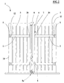
- numeral 1 indicates an extensible grate with ledge to protect the window or door openings essentially including transversal bars 2, vertical uprights 3, at least one 4 of which is external, a closure 5, locking members 5a, extension means 7 and two extension elements 8.
- the grate 1 is constituted by two shutters closed and hinged to the shoulders of an opening 10 of the related window or door. In the following it will be principally described only one shutter because the two shutters are equal and positioned lined up in their closing condition C, with the exception of the presence of only one closure 5 in the case of close shutters and whose external uprights almost interfere.
- Each shutter has two parallel transversal bars 2 to which a plurality of parallel and equally spaced uprights 3 are perpendicularly welded and whose number depends on the opening to protect, for instance varying from 2 to 8.
- Each shutter of the grate 1 is rotatably fixed to a shoulder of the opening 10 in correspondence of the ends of the transversal bars 2 by means of a first hinge 6.
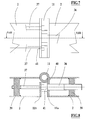
- the extension means 7 associated to the end of each transversal bar 2 hinged to the opening 10 include a first block 12 that is interposed between the end of said bar and the first hinge 6 and is constituted by an internal portion 12a slidably housed inside the transversal bar 2 and by a hollow portion 12b external to said bar.
- the first block 12 is provided with a plurality of threaded holes 13, engaged by corresponding grub screw 14 fit to space the internal portion 12a from a plate 15 fixed inside the transversal bar 2 for instance by means of welded joints 42 or rivets.
- the internal portion 12a of the block 12 has a through hole 16 crossed by locking means 17, for instance a screw, whose threaded end is fit in a corresponding threaded hole of the plate 15 and whose head 17a locks the hinge 6 against the hollow portion 12b in such a way to constrain this latter to a predefined distance from the transversal bar 2.
- the hinge 6 is provided with protrusions 18 lying on the surface of the hinge 6 in front of the hollow portion 12b of the first block 12 and fit in this latter in order to avoid the mutual rotation between the block and said hinge.
- the extension means 7 are constituted besides by a second block 20 that is interposed between the end of the transversal bar 2 and the external upright 4 and that has a first plurality of threaded holes 21, engaged by corresponding grub screws 22 fit to space the second block 20 from a stop 23 fixed inside the transversal bar 2, for instance by means of welded joints 43.
- the second block 20 has a plurality of through holes 24 crossed by the rod of clamping screws 25 whose threaded ends engage corresponding threaded holes carried out in the stop 23 and whose heads 25a mate the inner wall 4a of the external upright 4 so fixing this latter to the related transversal bar 2.
- extension means 7 are telescopically associated to each transversal bars 2 in such a way to adjust the width of the grate 1 to the opening 10 to be protected.
- the locking members 5a are connected to the closing 5, housed inside the external upright 4.
- Each locking members includes a rod 30, which is axially positioned inside the external upright 4, and which is fixed to a spacer 31 in correspondence of its end.
- a headless screw 32 To the free end of said spacer is screwed a headless screw 32 to whose remaining end is screwed a pawl 33 having an axial excursion by screwing or unscrewing said screw.
- the pawl 33 is provided with an axial threaded hole 34 in which a grub screw 35 is engaged having a tip 35a directed toward the pawl 33 and inserted into the pawl head in order to avoid its rotation whit respect to the headless screw 32.
- the installation of the grate 1 provides the adjustment of the width and height grate dimensions by using and adjusting the extension means 7, associated to the transversal bars, and the adjustment of the extension elements 8 housed in the external uprights.
- the protrusions 18 of the hinge 6 are inserted in the hollow portion 12b of the first block 12 and the screw 17 is screwed to the plate 15 locking the hinge 6 to the transversal bar 2 by compressing the head 17a of the crew 17 against said hinge which cannot rotate because of the engagement between the protrusions 18 and the inside edge of the hollow portion 12b of the first block 12.
- the distance of the second block 20 from the stop 23 is adjusted by screwing/unscrewing the grub screws 22, while the lock of the transversal bar 2 to the external upright 4 is made by clamping the screws 25 whose head compresses an inside wall of the external upright 4 against the second block 20.
- each locking members 5a is done by previously screwing the headless screw 32 into the spacer 31 and fixing, for instance by means of adhesive, and then screwing or unscrewing the pawl 33 on the headless screw 32 so causing respectively the shortening or the extension of the end of the relative rod 30.
- each extension element 8 of the relative external upright 4 by positioning at desired height said extension element and fixing this latter to the upright by tightening the screw 28.
- the grate 1 is constituted by a couple of shutters in which an external uprights 4 only has the closing 5 provided with a hook 47 suitable for hooking the upright 4 of the other shutter.
- a variant of the grate 1 is shown in figures 4 and 5 and provides the use of a cross-bar 9, upper and/or lower, whose ends are fixed to the shoulders of the opening 10 to be protected, for instance by means of a couple of wedges 46.
- Each of said cross-bar 9 is positioned at the outside of the grate 1, nearly parallelly to the transversal bars 2 so that the pawl 33 of the locking members 5a is engaged in a related hole of the cross-bar 9 in correspondence of a closing condition C of the grate 1.
- grate 1 two variants of the grate 1 which is constituted by a couple of shutters having the same external uprights 4, that is provided with the extension element 8 and the locking means 5a so that it is possible to install the couple of shutters with the external uprights 4 spaced.
- Said grate variant provides the use of a couple of closings 5, without the hook 47.
- FIG 5 shows a combination of the two preceding variants.
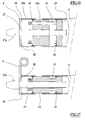
- Another variant of the grate 1, shown in the figures from 6 to 8, provides the use of a second hinge 11 interposed between the first hinge 6 and the peripheral upright 4 in such a way to allow 1 the opening of the grate 1 at around 180° beyond the shoulder of the opening 10 in order to open the grate 1 above possible casings external to said grate.
- the second hinge 11 has a first plate 11a having both a series of protrusion 40 fit to engage the inside edge of the transversal bar 2 in order to avoid the rotation of the second hinge 11, and a central hole 41 crossed by the rod of a screw 36 fit to engage with a first small plate 38 fixed inside said transversal bar 2, for instance by means of welded joints or rivets.
- the second hinge 11 further provides a second plate 11b having two holes 41 crossed by the rods of related screws 37 whose ends are engaged with a second small plate 39, fixed by means of welded joints or rivets, in order to lock the second plate 11b to the transversal bar 2.
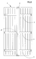
- the grate 1 can have another variant constituted by a grate suitable to protect the opening 10 of a door in which, as shown in figure 18 for instance, the transversal bars 2 are three instead of two and are equally spaced.
- the operator can screw the grub screw 35 with the tip 35a directed toward the cross-bar of the opening 10 so that, in correspondence of the closing condition C of the grate 1 and the activation of the closing 5, so activating the blocking means 5a, the tip 35a marks the precise point in which it is necessary to make the housing hole of the pawl 33.
- the second block 20 has an axial dimension of 35 mm and the relative grub screws 14 and 22 are 70 mm long, so that it is possible to obtain a width excursion of the two shutters from 1200 mm to 1390 mm.
- the first block 12 has varying axial dimensions, for instance, from 30 to 80 mm with regard to the opening 10 to be protected.
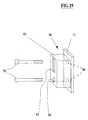
- a further variant, shown in figure 19, provides the use of the single shutter grate 1 in which the closing 5 has a stop 50, constituted by a plate 51, provided with two holes 56 to which a hollow block 52 is fixed, this latter having a slot 53, in which the hook 47 is engaged, in the closing condition C.
- Said stop 50 provides besides a further hole 54 through which a screw 55 passes for fixing the plate 51 to the shoulder of the opening 10.
- a further screw 55 passes through the slot 53 to cooperate for fixing the plate 51 so completely compressing the head of the screws 55 against the edge of the corresponding holes 56.
- the stop 50 allows to maintain spaced the external upright 4 from the shoulder of the opening 10 for allowing an easier opening of said grate and an easier installation and for avoiding the possible friction of the upright 4 against the shoulder of said opening.
- the grate operational adjustments are the same described for the preferred embodiment or for the variant suitable to protect the doors.
- the main advantage of the present invention is to provide a grate allowing the adjustment during the installation of its dimensions in width and height and therefore the fitting to the opening of the windows and the doors to be protected, without carrying out grates to measure.
- Further advantage of the present invention is to provide a grate having a simple realization, high reliability and safety and easy installation.
Landscapes
- Engineering & Computer Science (AREA)
- Structural Engineering (AREA)
- Architecture (AREA)
- Civil Engineering (AREA)
- Wing Frames And Configurations (AREA)
- Baking, Grill, Roasting (AREA)
- Devices For Use In Laboratory Experiments (AREA)
- Operating, Guiding And Securing Of Roll- Type Closing Members (AREA)
- Closing And Opening Devices For Wings, And Checks For Wings (AREA)
Applications Claiming Priority (2)
| Application Number | Priority Date | Filing Date | Title |
|---|---|---|---|
| ITBO000050 | 2000-02-04 | ||
| IT2000BO000050A IT1321207B1 (it) | 2000-02-04 | 2000-02-04 | Grata battente estendibile per proteggere l' apertura di finestre eporte. |
Publications (3)
| Publication Number | Publication Date |
|---|---|
| EP1122397A2 true EP1122397A2 (de) | 2001-08-08 |
| EP1122397A3 EP1122397A3 (de) | 2002-06-12 |
| EP1122397B1 EP1122397B1 (de) | 2004-06-09 |
Family
ID=11438139
Family Applications (1)
| Application Number | Title | Priority Date | Filing Date |
|---|---|---|---|
| EP01102390A Expired - Lifetime EP1122397B1 (de) | 2000-02-04 | 2001-02-02 | Ausziehbares Gitter zum Schutz der Öffnung von Fenstern und Türen |
Country Status (4)
| Country | Link |
|---|---|
| EP (1) | EP1122397B1 (de) |
| AT (1) | ATE268860T1 (de) |
| DE (1) | DE60103672D1 (de) |
| IT (1) | IT1321207B1 (de) |
Cited By (1)
| Publication number | Priority date | Publication date | Assignee | Title |
|---|---|---|---|---|
| ITRN20120055A1 (it) * | 2012-12-06 | 2014-06-07 | Ing Diego Nobili | Anta basculante. |
Family Cites Families (5)
| Publication number | Priority date | Publication date | Assignee | Title |
|---|---|---|---|---|
| DE261328C (de) * | ||||
| US5307858A (en) * | 1992-03-12 | 1994-05-03 | Turner Jean A | Universal window shutter system |
| GB9420715D0 (en) * | 1994-10-14 | 1994-11-30 | Beldray Ltd | Improvements relating to nursery gates |
| US5657809A (en) * | 1995-09-01 | 1997-08-19 | Kids Ii, Inc. | Security gate |
| FR2760039B1 (fr) * | 1997-02-27 | 1999-05-14 | G M S | Dispositif de fermeture articule pour ouverture de batiment |
-
2000
- 2000-02-04 IT IT2000BO000050A patent/IT1321207B1/it active
-
2001
- 2001-02-02 AT AT01102390T patent/ATE268860T1/de not_active IP Right Cessation
- 2001-02-02 EP EP01102390A patent/EP1122397B1/de not_active Expired - Lifetime
- 2001-02-02 DE DE60103672T patent/DE60103672D1/de not_active Expired - Lifetime
Cited By (1)
| Publication number | Priority date | Publication date | Assignee | Title |
|---|---|---|---|---|
| ITRN20120055A1 (it) * | 2012-12-06 | 2014-06-07 | Ing Diego Nobili | Anta basculante. |
Also Published As
| Publication number | Publication date |
|---|---|
| ITBO20000050A1 (it) | 2001-08-04 |
| EP1122397A3 (de) | 2002-06-12 |
| DE60103672D1 (de) | 2004-07-15 |
| ATE268860T1 (de) | 2004-06-15 |
| EP1122397B1 (de) | 2004-06-09 |
| IT1321207B1 (it) | 2003-12-31 |
Similar Documents
| Publication | Publication Date | Title |
|---|---|---|
| US4438597A (en) | Adjustable hinge mount | |
| US5581948A (en) | Kick resistant door assembly | |
| US5289655A (en) | Safety release security grille | |
| EP0022334B1 (de) | Schutzgitter | |
| US4615142A (en) | Burglar bars | |
| US5447345A (en) | Security bar | |
| US4142747A (en) | Double-locking assembly for sliding glass closures | |
| EP1122397B1 (de) | Ausziehbares Gitter zum Schutz der Öffnung von Fenstern und Türen | |
| EP0256788A2 (de) | Sicherheitsbarrieren | |
| GB2272472A (en) | Telescopic clamping bar for a security door | |
| US5910076A (en) | Extensible window and door guard | |
| RU2001132083A (ru) | Петля для дверей, окон и т.п. | |
| GB2457994A (en) | Security device for sliding door | |
| SE526417C2 (sv) | Anordning vid dörrar | |
| SK31397A3 (en) | Alarm-triggering closure device for the closure and/or hinge area of a door or window to be made secure | |
| EP3533965B1 (de) | Faltbares gitter für fenster und türen | |
| US7350837B1 (en) | Door jam security device and method of using same | |
| GB2127078A (en) | Reinforcement for doors | |
| US6922959B1 (en) | Apparatus and method for correcting a misaligned door and door frame | |
| IE53361B1 (en) | A fastening means for padlocks and the like | |
| GB2449287A (en) | Security apparatus using a padlock | |
| CA1146016A (en) | Window security bars | |
| GB2584544A (en) | Improvements to letter-plates | |
| US5524943A (en) | Security device | |
| RU2008147104A (ru) | Дверной блок с замковой и с петлевой защитными дверцами (варианты) и способ изготовления, сборки и модернизации дверных блоков с защитными элементами (варианты) |
Legal Events
| Date | Code | Title | Description |
|---|---|---|---|
| PUAI | Public reference made under article 153(3) epc to a published international application that has entered the european phase |
Free format text: ORIGINAL CODE: 0009012 |
|
| AK | Designated contracting states |
Kind code of ref document: A2 Designated state(s): AT BE CH CY DE DK ES FI FR GB GR IE IT LI LU MC NL PT SE TR |
|
| AX | Request for extension of the european patent |
Free format text: AL;LT;LV;MK;RO;SI |
|
| PUAL | Search report despatched |
Free format text: ORIGINAL CODE: 0009013 |
|
| AK | Designated contracting states |
Kind code of ref document: A3 Designated state(s): AT BE CH CY DE DK ES FI FR GB GR IE IT LI LU MC NL PT SE TR |
|
| AX | Request for extension of the european patent |
Free format text: AL;LT;LV;MK;RO;SI |
|
| 17P | Request for examination filed |
Effective date: 20021212 |
|
| AKX | Designation fees paid |
Designated state(s): AT BE CH CY DE DK ES FI FR GB GR IE IT LI LU MC NL PT SE TR |
|
| GRAP | Despatch of communication of intention to grant a patent |
Free format text: ORIGINAL CODE: EPIDOSNIGR1 |
|
| GRAS | Grant fee paid |
Free format text: ORIGINAL CODE: EPIDOSNIGR3 |
|
| GRAA | (expected) grant |
Free format text: ORIGINAL CODE: 0009210 |
|
| AK | Designated contracting states |
Kind code of ref document: B1 Designated state(s): AT BE CH CY DE DK ES FI FR GB GR IE IT LI LU MC NL PT SE TR |
|
| PG25 | Lapsed in a contracting state [announced via postgrant information from national office to epo] |
Ref country code: FR Free format text: LAPSE BECAUSE OF FAILURE TO SUBMIT A TRANSLATION OF THE DESCRIPTION OR TO PAY THE FEE WITHIN THE PRESCRIBED TIME-LIMIT Effective date: 20040609 Ref country code: LI Free format text: LAPSE BECAUSE OF FAILURE TO SUBMIT A TRANSLATION OF THE DESCRIPTION OR TO PAY THE FEE WITHIN THE PRESCRIBED TIME-LIMIT Effective date: 20040609 Ref country code: CH Free format text: LAPSE BECAUSE OF FAILURE TO SUBMIT A TRANSLATION OF THE DESCRIPTION OR TO PAY THE FEE WITHIN THE PRESCRIBED TIME-LIMIT Effective date: 20040609 Ref country code: FI Free format text: LAPSE BECAUSE OF FAILURE TO SUBMIT A TRANSLATION OF THE DESCRIPTION OR TO PAY THE FEE WITHIN THE PRESCRIBED TIME-LIMIT Effective date: 20040609 Ref country code: AT Free format text: LAPSE BECAUSE OF FAILURE TO SUBMIT A TRANSLATION OF THE DESCRIPTION OR TO PAY THE FEE WITHIN THE PRESCRIBED TIME-LIMIT Effective date: 20040609 Ref country code: NL Free format text: LAPSE BECAUSE OF FAILURE TO SUBMIT A TRANSLATION OF THE DESCRIPTION OR TO PAY THE FEE WITHIN THE PRESCRIBED TIME-LIMIT Effective date: 20040609 Ref country code: TR Free format text: LAPSE BECAUSE OF FAILURE TO SUBMIT A TRANSLATION OF THE DESCRIPTION OR TO PAY THE FEE WITHIN THE PRESCRIBED TIME-LIMIT Effective date: 20040609 Ref country code: BE Free format text: LAPSE BECAUSE OF FAILURE TO SUBMIT A TRANSLATION OF THE DESCRIPTION OR TO PAY THE FEE WITHIN THE PRESCRIBED TIME-LIMIT Effective date: 20040609 |
|
| REG | Reference to a national code |
Ref country code: GB Ref legal event code: FG4D |
|
| REG | Reference to a national code |
Ref country code: CH Ref legal event code: EP |
|
| REF | Corresponds to: |
Ref document number: 60103672 Country of ref document: DE Date of ref document: 20040715 Kind code of ref document: P |
|
| REG | Reference to a national code |
Ref country code: IE Ref legal event code: FG4D |
|
| PG25 | Lapsed in a contracting state [announced via postgrant information from national office to epo] |
Ref country code: SE Free format text: LAPSE BECAUSE OF FAILURE TO SUBMIT A TRANSLATION OF THE DESCRIPTION OR TO PAY THE FEE WITHIN THE PRESCRIBED TIME-LIMIT Effective date: 20040909 Ref country code: GR Free format text: LAPSE BECAUSE OF FAILURE TO SUBMIT A TRANSLATION OF THE DESCRIPTION OR TO PAY THE FEE WITHIN THE PRESCRIBED TIME-LIMIT Effective date: 20040909 Ref country code: DK Free format text: LAPSE BECAUSE OF FAILURE TO SUBMIT A TRANSLATION OF THE DESCRIPTION OR TO PAY THE FEE WITHIN THE PRESCRIBED TIME-LIMIT Effective date: 20040909 |
|
| PG25 | Lapsed in a contracting state [announced via postgrant information from national office to epo] |
Ref country code: DE Free format text: LAPSE BECAUSE OF FAILURE TO SUBMIT A TRANSLATION OF THE DESCRIPTION OR TO PAY THE FEE WITHIN THE PRESCRIBED TIME-LIMIT Effective date: 20040910 |
|
| PG25 | Lapsed in a contracting state [announced via postgrant information from national office to epo] |
Ref country code: ES Free format text: LAPSE BECAUSE OF FAILURE TO SUBMIT A TRANSLATION OF THE DESCRIPTION OR TO PAY THE FEE WITHIN THE PRESCRIBED TIME-LIMIT Effective date: 20040920 |
|
| NLV1 | Nl: lapsed or annulled due to failure to fulfill the requirements of art. 29p and 29m of the patents act | ||
| REG | Reference to a national code |
Ref country code: CH Ref legal event code: PL |
|
| PG25 | Lapsed in a contracting state [announced via postgrant information from national office to epo] |
Ref country code: LU Free format text: LAPSE BECAUSE OF NON-PAYMENT OF DUE FEES Effective date: 20050202 Ref country code: CY Free format text: LAPSE BECAUSE OF FAILURE TO SUBMIT A TRANSLATION OF THE DESCRIPTION OR TO PAY THE FEE WITHIN THE PRESCRIBED TIME-LIMIT Effective date: 20050202 Ref country code: IE Free format text: LAPSE BECAUSE OF NON-PAYMENT OF DUE FEES Effective date: 20050202 Ref country code: GB Free format text: LAPSE BECAUSE OF NON-PAYMENT OF DUE FEES Effective date: 20050202 |
|
| PG25 | Lapsed in a contracting state [announced via postgrant information from national office to epo] |
Ref country code: MC Free format text: LAPSE BECAUSE OF NON-PAYMENT OF DUE FEES Effective date: 20050228 |
|
| PLBE | No opposition filed within time limit |
Free format text: ORIGINAL CODE: 0009261 |
|
| STAA | Information on the status of an ep patent application or granted ep patent |
Free format text: STATUS: NO OPPOSITION FILED WITHIN TIME LIMIT |
|
| 26N | No opposition filed |
Effective date: 20050310 |
|
| EN | Fr: translation not filed | ||
| GBPC | Gb: european patent ceased through non-payment of renewal fee |
Effective date: 20050202 |
|
| REG | Reference to a national code |
Ref country code: IE Ref legal event code: MM4A |
|
| PG25 | Lapsed in a contracting state [announced via postgrant information from national office to epo] |
Ref country code: PT Free format text: LAPSE BECAUSE OF NON-PAYMENT OF DUE FEES Effective date: 20041109 |
|
| PGFP | Annual fee paid to national office [announced via postgrant information from national office to epo] |
Ref country code: IT Payment date: 20120203 Year of fee payment: 12 |
|
| PG25 | Lapsed in a contracting state [announced via postgrant information from national office to epo] |
Ref country code: IT Free format text: LAPSE BECAUSE OF NON-PAYMENT OF DUE FEES Effective date: 20130202 |