EP1122431A2 - Circuit de commande d'un compresseur à capacité variable - Google Patents
Circuit de commande d'un compresseur à capacité variable Download PDFInfo
- Publication number
- EP1122431A2 EP1122431A2 EP01102570A EP01102570A EP1122431A2 EP 1122431 A2 EP1122431 A2 EP 1122431A2 EP 01102570 A EP01102570 A EP 01102570A EP 01102570 A EP01102570 A EP 01102570A EP 1122431 A2 EP1122431 A2 EP 1122431A2
- Authority
- EP
- European Patent Office
- Prior art keywords
- temperature
- differential pressure
- evaporator
- limit value
- pressure
- Prior art date
- Legal status (The legal status is an assumption and is not a legal conclusion. Google has not performed a legal analysis and makes no representation as to the accuracy of the status listed.)
- Withdrawn
Links
Images


Classifications
-
- F—MECHANICAL ENGINEERING; LIGHTING; HEATING; WEAPONS; BLASTING
- F04—POSITIVE - DISPLACEMENT MACHINES FOR LIQUIDS; PUMPS FOR LIQUIDS OR ELASTIC FLUIDS
- F04B—POSITIVE-DISPLACEMENT MACHINES FOR LIQUIDS; PUMPS
- F04B27/00—Multi-cylinder pumps specially adapted for elastic fluids and characterised by number or arrangement of cylinders
- F04B27/08—Multi-cylinder pumps specially adapted for elastic fluids and characterised by number or arrangement of cylinders having cylinders coaxial with, or parallel or inclined to, main shaft axis
- F04B27/14—Control
- F04B27/16—Control of pumps with stationary cylinders
- F04B27/18—Control of pumps with stationary cylinders by varying the relative positions of a swash plate and a cylinder block
- F04B27/1804—Controlled by crankcase pressure
-
- F—MECHANICAL ENGINEERING; LIGHTING; HEATING; WEAPONS; BLASTING
- F04—POSITIVE - DISPLACEMENT MACHINES FOR LIQUIDS; PUMPS FOR LIQUIDS OR ELASTIC FLUIDS
- F04B—POSITIVE-DISPLACEMENT MACHINES FOR LIQUIDS; PUMPS
- F04B49/00—Control, e.g. of pump delivery, or pump pressure of, or safety measures for, machines, pumps, or pumping installations, not otherwise provided for, or of interest apart from, groups F04B1/00 - F04B47/00
- F04B49/06—Control using electricity
- F04B49/065—Control using electricity and making use of computers
-
- F—MECHANICAL ENGINEERING; LIGHTING; HEATING; WEAPONS; BLASTING
- F04—POSITIVE - DISPLACEMENT MACHINES FOR LIQUIDS; PUMPS FOR LIQUIDS OR ELASTIC FLUIDS
- F04B—POSITIVE-DISPLACEMENT MACHINES FOR LIQUIDS; PUMPS
- F04B27/00—Multi-cylinder pumps specially adapted for elastic fluids and characterised by number or arrangement of cylinders
- F04B27/08—Multi-cylinder pumps specially adapted for elastic fluids and characterised by number or arrangement of cylinders having cylinders coaxial with, or parallel or inclined to, main shaft axis
- F04B27/14—Control
- F04B27/16—Control of pumps with stationary cylinders
- F04B27/18—Control of pumps with stationary cylinders by varying the relative positions of a swash plate and a cylinder block
- F04B27/1804—Controlled by crankcase pressure
- F04B2027/1809—Controlled pressure
- F04B2027/1813—Crankcase pressure
-
- F—MECHANICAL ENGINEERING; LIGHTING; HEATING; WEAPONS; BLASTING
- F04—POSITIVE - DISPLACEMENT MACHINES FOR LIQUIDS; PUMPS FOR LIQUIDS OR ELASTIC FLUIDS
- F04B—POSITIVE-DISPLACEMENT MACHINES FOR LIQUIDS; PUMPS
- F04B27/00—Multi-cylinder pumps specially adapted for elastic fluids and characterised by number or arrangement of cylinders
- F04B27/08—Multi-cylinder pumps specially adapted for elastic fluids and characterised by number or arrangement of cylinders having cylinders coaxial with, or parallel or inclined to, main shaft axis
- F04B27/14—Control
- F04B27/16—Control of pumps with stationary cylinders
- F04B27/18—Control of pumps with stationary cylinders by varying the relative positions of a swash plate and a cylinder block
- F04B27/1804—Controlled by crankcase pressure
- F04B2027/1822—Valve-controlled fluid connection
- F04B2027/1827—Valve-controlled fluid connection between crankcase and discharge chamber
-
- F—MECHANICAL ENGINEERING; LIGHTING; HEATING; WEAPONS; BLASTING
- F04—POSITIVE - DISPLACEMENT MACHINES FOR LIQUIDS; PUMPS FOR LIQUIDS OR ELASTIC FLUIDS
- F04B—POSITIVE-DISPLACEMENT MACHINES FOR LIQUIDS; PUMPS
- F04B27/00—Multi-cylinder pumps specially adapted for elastic fluids and characterised by number or arrangement of cylinders
- F04B27/08—Multi-cylinder pumps specially adapted for elastic fluids and characterised by number or arrangement of cylinders having cylinders coaxial with, or parallel or inclined to, main shaft axis
- F04B27/14—Control
- F04B27/16—Control of pumps with stationary cylinders
- F04B27/18—Control of pumps with stationary cylinders by varying the relative positions of a swash plate and a cylinder block
- F04B27/1804—Controlled by crankcase pressure
- F04B2027/184—Valve controlling parameter
- F04B2027/1854—External parameters
-
- F—MECHANICAL ENGINEERING; LIGHTING; HEATING; WEAPONS; BLASTING
- F04—POSITIVE - DISPLACEMENT MACHINES FOR LIQUIDS; PUMPS FOR LIQUIDS OR ELASTIC FLUIDS
- F04B—POSITIVE-DISPLACEMENT MACHINES FOR LIQUIDS; PUMPS
- F04B27/00—Multi-cylinder pumps specially adapted for elastic fluids and characterised by number or arrangement of cylinders
- F04B27/08—Multi-cylinder pumps specially adapted for elastic fluids and characterised by number or arrangement of cylinders having cylinders coaxial with, or parallel or inclined to, main shaft axis
- F04B27/14—Control
- F04B27/16—Control of pumps with stationary cylinders
- F04B27/18—Control of pumps with stationary cylinders by varying the relative positions of a swash plate and a cylinder block
- F04B27/1804—Controlled by crankcase pressure
- F04B2027/184—Valve controlling parameter
- F04B2027/1859—Suction pressure
-
- F—MECHANICAL ENGINEERING; LIGHTING; HEATING; WEAPONS; BLASTING
- F04—POSITIVE - DISPLACEMENT MACHINES FOR LIQUIDS; PUMPS FOR LIQUIDS OR ELASTIC FLUIDS
- F04B—POSITIVE-DISPLACEMENT MACHINES FOR LIQUIDS; PUMPS
- F04B2205/00—Fluid parameters
- F04B2205/07—Pressure difference over the pump
Definitions
- the present invention relates to an apparatus and a method for controlling discharge capacity of a variable displacement compressor of an automotive air conditioner.
- a refrigerant circuit of an'automotive air conditioner includes a condenser, an expansion valve, an evaporator, and a compressor.
- the compressor draws and compresses refrigerant gas from the evaporator and discharges the refrigerant gas to the condenser.
- the evaporator transfers heat to refrigerant passing through the refrigerant circuit from air flowing inside a vehicle. Since the heat of the air passing through the evaporator is transmitted to the refrigerant passing through the evaporator in accordance with the size of the air conditioning load, the pressure of the refrigerant gas at the outlet, or downstream end of the evaporator, reflects the size of the air conditioning load.
- a swash plate type variable displacement compressor which has been widely used in vehicles, is provided with a capacity control mechanism, which is operated to hold the pressure of the outlet of the evaporator (hereinafter referred to as the suction pressure (Ps)) to a predetermined target value (hereinafter referred to as the set suction pressure).
- the capacity control mechanism feedback controls the discharge capacity of the compressor, or the angle of the swash plate, using the suction pressure Ps as a control index such that the flow rate of the refrigerant corresponds to the size of the air conditioning load.
- a typical example of a capacity control mechanism is an internal control valve.
- the internal control valve detects the suction pressure Ps with a pressure-sensing member, such as bellows or a diaphragm, and adjusts the pressure (the crank pressure) of a swash plate chamber (or crank chamber) by using displacement of the pressure-sensing member to position a valve body.
- the position of the valve body determines the angle of the swash plate.
- a set suction pressure variable type control valve in which the set suction pressure can be changed by external electric control, is needed.
- a set suction pressure variable type control valve changes the set suction pressure by using an actuator, the force of which is electrically controllable.
- the actuator may be an electronic solenoid. The actuator increments or decrements the force acting on the pressure-reducing member, which determines the set suction pressure of the internal control valve.
- An objective of the present invention is to provide a control apparatus and a control method of a variable displacement compressor which can improve the control property and responsivity of the discharge capacity.
- the present invention provides a control apparatus for controlling discharge capacity of a variable displacement compressor included in a refrigeration circuit of an air conditioner.
- the refrigeration circuit includes an evaporator.
- the control apparatus includes a differential pressure detector, a temperature sensor, a set differential pressure calculator, a limit value setting device, a set differential pressure setting device and a compressor control mechanism.
- the differential pressure detector detects a differential pressure between two pressure monitoring points set to said refrigeration circuit, on which the discharge capacity of the variable displacement compressor is reflected.
- the temperature sensor detects a cooling state of the evaporator as temperature information.
- the set differential pressure calculator calculates a set differential pressure which becomes a control target of a differential pressure between the two pressure monitoring points, based on a temperature detected by the temperature sensor of the evaporator and a target temperature which is a control target of the temperature of the evaporator.
- the limit value setting device sets a limit value to the differential pressure between the two pressure monitoring points when the temperature detected by the temperature sensor of the evaporator is lowered from the state higher than a threshold temperature which is set to higher than the target temperature to the state lower than the threshold temperature, and releases the setting of the limit value when the temperature detected by the temperature sensor of the evaporator is raised from the state lower than the threshold temperature to the state higher than the threshold temperature.
- the set differential pressure setting device compares the set differential pressure calculated by the set differential pressure calculator with the limit value set by the limit value setting device, deals with the set differential pressure in itself if the discharge capacity of the variable displacement compressor which the set differential pressure represents is less than that of the variable displacement compressor which the limit value represents, and deals with the limit value as a new set differential pressure if the discharge capacity of the variable displacement compressor which the set differential pressure represents is greater than that of the variable displacement compressor which the limit value represents.
- the compressor control mechanism controls the discharge capacity of the variable displacement compressor so that the differential pressure detected by the differential pressure detector approaches to the set differential pressure from the set differential pressure setting device.
- the present invention also provides a method for controlling discharge capacity of a variable displacement compressor included in a refrigeration circuit of an air conditioner.
- the refrigeration circuit includes an evaporator.
- the method includes the steps of: detecting a differential pressure between two pressure monitoring points set to said refrigeration circuit, on which the discharge capacity of the variable displacement compressor is reflected; detecting a cooling state of the evaporator as temperature information; calculating a set differential pressure which becomes a control target of a differential pressure between the two pressure monitoring points based on the temperature information and a target temperature which is a control target of the temperature of the evaporator; setting a limit value to the differential pressure between the two pressure monitoring points when the temperature information is lowered from the state higher than a threshold temperature which is set to higher than the target temperature to the state lower than the threshold temperature, and releasing the setting of the limit.
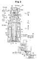
- the swash plate type variable displacement compressor (hereinafter referred to as the compressor) includes a cylinder block 11, a front housing 12 fixed to the front end of the cylinder block 11, and a rear housing 14 securely fixed to the rear end of the cylinder block 11 through a valve/port forming body 13.
- a crank chamber 15 is surrounded by the cylinder block 11 and the front housing 12.
- a drive shaft 16 extends through the crank chamber 15 so that the drive shaft 16 is rotatably supported by the cylinder block 11 and the front housing 12.
- a lug plate 17 is integrally and rotatably fixed to the drive shaft 16 in the crank chamber 15.
- the front end of the drive shaft 16 is operatively connected to an automotive engine Eg, which functions as an external drive source, through a power transmitting mechanism PT.
- the power transmitting mechanism PT may be a clutch mechanism (for example, an electronic clutch), which can engage and disengage the clutch electronically or it may be a clutchless mechanism, which does not have a clutch mechanism (for example, the transmission may be a combination of a belt and a pulley).
- a clutchless type power transmitting mechanism PT is used,
- the swash plate 18, which functions as a cam plate, is accommodated in the crank chamber 15.
- the swash plate 18 slides on the surface of the drive shaft 16 in the axial direction, and the swash plate 18 inclines with respect to the axis of the drive shaft 16.
- a hinge mechanism 19 is located between the lug plate 17 and the swash plate 18. Accordingly, the swash plate 18 is driven integrally with the lug plate 17 and the drive shaft 16 by the hinge mechanism 19.
- Cylinder bores 20 (only one cylinder bore is shown) are arranged about the drive shaft 16 in the cylinder block 11.
- a single-head type piston 21 is accommodated in each cylinder bore 20.
- the front and rear openings of the cylinder bores 20 are closed by the valve/port forming body 13 and the piston 21, and a compression chamber, the volume of which is changed in accordance with the piston motion is defined in each cylinder bore 20.
- Each piston 21 is connected to the periphery of the swash plate 18 through a set of shoes 28. Accordingly, rotation of the swash plate 18 by the rotation of the drive shaft 16 is converted to reciprocation of the pistons 21 by the shoes 28.
- a suction chamber 22, which is included in a suction pressure Ps region and a discharge chamber 23, which is included in a discharge pressure Pd region, are defined by the valve/port forming body 13 and the rear housing 14, as shown in Fig. 1. Also, when the piston 21 moves from top dead center to bottom dead center, the refrigerant gas of the suction chamber 22 is drawn into the corresponding cylinder bore 20 (compression chamber) through a corresponding suction port 24 and a corresponding suction valve 25 of the valve/port forming body 13.
- the refrigerant gas drawn into the cylinder bores 20 is compressed to a predetermined pressure by movement of the pistons 21 from bottom dead center to top dead center and is then discharged to the discharge chamber 23 through the discharge ports 26 and the discharge valves 27 of the valve/port forming body 13.
- the angle of inclination of the swash plate 18 (the angle formed between the swash plate 18 and an imaginary plane that is perpendicular to the drive shaft 16) can be adjusted by changing the relationship between internal pressure (crank pressure Pc) of the crank chamber 15, which is the back pressure of the pistons 21, and the internal pressure of the cylinder bores 20 (compression chambers).
- crank pressure Pc internal pressure of the crank chamber 15
- the angle of inclination of the swash plate 18 is adjusted by changing the crank pressure Pc.
- the refrigeration circuit of the automotive air conditioner includes the compressor and a external refrigerant circuit 35.
- the external refrigerant circuit 35 includes a condenser 36, a thermostatic expansion valve 37, and an evaporator 38.
- the opening degree of the expansion valve 37 is feedback controlled based on an evaporation pressure (the discharge pressure of the evaporator 38) and the temperature detected by a temperature sensor 37a placed at the outlet side, or the downstream side, of the evaporator 38.
- the expansion valve 37 supplies the evaporator 38 with liquid refrigerant, the pressure of which corresponds to the heat load, and adjusts the flow rate of the refrigerant in the external refrigerant circuit 35.
- a downstream pipe 39 connects the suction chamber 22 of the compressor with the outlet of the evaporator 38 in the downstream region of the external refrigerant circuit 35.
- An upstream pipe 40 connects the discharge chamber 23 of the compressor with the inlet of the condenser 36 in the upstream region of the external refrigerant circuit 35.
- the compressor draws and compresses the refrigerant gas from the downstream region of the external refrigerant circuit 35 to the suction chamber 25 and discharges the compressed gas to the discharge chamber 23 connected to the upstream region of the external refrigerant circuit 35.
- the pressure loss per unit length of the circuit, or the pipe is also increased. That is, the pressure loss (differential pressure) between a first pressure monitoring point P1 and a second pressure monitoring point P2 in the refrigerant circuit correlates with the flow rate of the refrigerant in the refrigerant circulator. Accordingly, to detect the difference (PdH-PdL) between the gas pressure (PdH) of the first pressure monitoring point P1 and the gas pressure (PdL) of the second pressure monitoring point P2, the flow rate of the refrigerant in the refrigerant circuit must be indirectly detected.
- the first pressure monitoring point P1 (the high pressure point) is any point in the discharge chamber 23 corresponding to the most upstream region of the upstream pipe 40.
- the second pressure monitoring point P2 (the low pressure point) is a point in the upstream pipe 40 that is spaced from the first pressure monitoring point by a predetermined distance.
- the flow rate of the refrigerant in the following refrigerant circuit can be represented as the product of the rotating speed of the drive shaft 16 and the discharge amount (the discharge capacity) of the refrigerant gas per unit rotation of the drive shaft 16 in the compressor.
- the rotating speed of the drive shaft 16 can be calculated from the pulley rate of the power transmitting mechanism PT and the rotating speed of the automotive engine Eg (the output shaft). In other words, when the rotating speed of the automotive engine Eg is constant, the flow rate of the refrigerant in the refrigerant circuit is increased when the discharge capacity of the compressor is increased, and the flow rate of the refrigerant in the refrigerant circuit is decreased when the discharge capacity of the compressor is decreased.
- a fixed throttle 43 is arranged between the pressure monitoring points P1 and P2 in the upstream pipe 40.
- the throttle 43 increases the differential pressure between the points P1 and P2.
- the fixed throttle 43 increases the differential pressure PdH-PdL between the two points P1 and P2, though the pressure monitoring points P1 and P2 are not far apart from each other. Since the fixed throttle 43 is located between the pressure monitoring points P1, P2, the second pressure monitoring point P2 can be positioned in the vicinity of the compressor (the discharge chamber 23), and a second detecting passage 42, which extends between a control valve 46 mounted in the compressor and the second pressure monitoring point P2, can be shortened.
- crank pressure control mechanism The crank pressure control mechanism
- the crank pressure control mechanism for controlling the crank pressure Pc of the compressor, includes a release passage 31, a first pressure sensing passage 41, a second pressure sensing passage 42, a supply passage 44, a control valve 46.
- the release passage 31 communicates the crank chamber 15 with the suction chamber 22.
- the first pressure sensing passage 41 connects the first pressure monitoring point P1 of the refrigerant circuit with the control valve 46.
- the second pressure sensing passage 42 connects the second pressure detecting point P2 of the refrigerant circuit with the control valve 46.
- the supply passage 44 connects the control valve 46 with the crank chamber 15.
- the opening degree of the control valve 46 By adjusting the opening degree of the control valve 46, the relationship between the flow rate of high pressure discharge gas flowing from the second pressure monitoring point P2 to the crank chamber 15 through the second pressure sensing passage 42 and the supply passage 44 and the flow rate of gas discharged from the crank chamber 15 to the suction chamber 22 through the release passage 31 is controlled, which determines the crank pressure Pc.
- the difference between the internal pressure of the cylinder bores 20 and the crank pressure Pc varies in accordance with variation of the crank pressure Pc, and the inclination of the swash plate 18 varies accordingly.
- the stroke of each piston 21, of the discharge capacity is adjusted in accordance with the inclination angle of the swash plate 18.
- the control valve 46 includes an inlet valve portion 51 at the top and a solenoid portion 52 at the bottom.
- the solenoid portion 52 is also called an electric drive portion.
- the valve portion 51 adjusts the opening degree (throttling amount) of the supply passage 44.
- the solenoid portion 52 is an electronic actuator for controlling an operating rod 53, which is arranged in the control valve 45, based on external electric current control.
- the operating rod 53 includes a divider portion 54, a connecting portion 55, a valve portion 56, or valve body, and a guiding rod portion 57.
- the valve portion 56 is located at the upper end of the guiding rod portion 57.
- a valve housing 58 of the control valve 46 includes a cap 58a, an upper body 58b, which forms a main outer wall of the inlet valve portion 51, and a lower body 58c, which forms a main outer wall of the solenoid portion 52.
- a valve chamber 59 and a communicating passage 60 are formed in the upper body 58b of the valve housing 58.
- a high pressure chamber 65 is formed between the upper body 58b and the cap 58a, which is threaded to the upper body 58b.
- the operating rod 53 is arranged to move in the valve chamber 59, the communicating passage 60, and the high pressure chamber 65 in an axial direction of the valve housing 58.
- the valve chamber 59 and the communicating passage 60 can communicate in accordance with the position of the operating rod 53.
- a bottom wall of the valve chamber 59 is provided by a top end surface of a fixed core 70 of the solenoid portion 52.
- a first radial port 62 extends through the main wall of the valve housing 58 surrounding the valve chamber 59.
- the first radial port 62 connects the valve chamber 59 with the second pressure monitoring point P2 through the second pressure sensing passage 42. Accordingly, the low pressure PdL of the second monitoring point P2 is applied to the valve chamber 59 through the second pressure sensing passage 42 and the first port 62.
- a second port 63 is arranged to extend radially through the main wall of the valve housing 58 surrounding the communication passage 60.
- the second port 63 connects the communicating passage 60 with the crank chamber 15 through the supply passage 44. Accordingly, the valve chamber 59 and the communicating passage 60 form a part of the supply passage 44 that passes through the control valve and applies the pressure of the second pressure monitoring point P2 to the crank chamber 15.
- the valve portion 56 of the operating rod 53 is located in the valve chamber 59.
- the diameter of the aperture of the communicating passage 60 is larger than that of the connecting portion 55 of the operating rod 53 so that gas flows smoothly.
- a step located at the boundary between the communicating passage 60 and the valve chamber 59 functions as a valve seat 64, and the communicating passage 60 is a valve aperture.
- the divider portion 54 of the operating rod 53 is fitted into the high pressure chamber 65.
- the divider portion 54 serves as a partition between the high pressure chamber 65 and the communicating passage 60. Therefore the high pressure chamber 65 does not communicate with the communicating passage 60 directly.
- a third port 67 is formed in the main wall of the valve housing 58 surrounding the high pressure chamber 65.
- the high pressure chamber 65 always communicates with the discharge chamber 23, which is the location of the first pressure monitoring point P1, through the third port 67 and the first pressure sensing passage 41. Accordingly, the high pressure PdH is applied to the high pressure chamber 65 through the first pressure sensing passage 41 and the third port 67,
- a return spring 68 is accommodated in the high pressure chamber 65. The return spring 68 applies axial force to the divider portion 54 (or to the operating rod 53).
- the solenoid portion 52 includes a cylindrical barrel 69 having a bottom.
- the fixed core 70 is fitted into the top portion of the barrel 69, and the barrel 69 forms a plunger chamber 71.
- a plunger (the moving core) 72 is accommodated in the plunger chamber 71 and is moveable in the axial direction.
- a guiding hole 73 is formed in the fixed core 70.
- the guiding rod portion 57 of the operating rod 53 is fitted in the guiding hole 73 and is moveable in the axial direction.
- a clearance (not shown) is formed between the internal wall surface of the guiding hole 73 and the guiding rod portion 57.
- the lower end of the guiding rod portion 57 is fixed to the plunger 72. Accordingly, the operating rod 53 moves integrally with the plunger 72.
- a buffer spring 74 is located in the plunger chamber 71. The elastic force of the buffer spring 74 urges the plunger 72 toward the fixed core 70, which urges the operating rod 53 in an upward direction in the drawings. The force of the buffer spring 74 is smaller than that of the return spring 68.
- a coil 75 is wound in the vicinity of the plunger 72 and the fixed core 70 in a range that covers them.
- the coil 75 is supplied with a driving signal from a driving circuit 82, based on a command from a computer 81, and the coil 75 generates an electronic force F, the magnitude of which depends on the level of the driving signal.
- the plunger 72 is attracted to the fixed core 70 by the electronic force F, and the operating rod 53 moves upward.
- the current flowing to the coil 75 is varied by adjusting the voltage applied to the coil 75.
- a duty control method has been employed.
- the high pressure PdH of the high pressure chamber 65 is applied to the operating rod 53 in the downward direction of Fig. 3, as is the force f1 of the return spring 68.
- the low pressure PdL is applied to the guide rod portion 57 in the upward direction.
- the electronic force F generated between the fixed core 70 and the plunger 72 is applied to the operating rod 53 in the upward direction, like the force f2 of the buffer spring 74.
- the adjustment of the opening degree of the control valve 46 namely, the adjustment of the opening degree of the communicating passage 60, is internally performed based on changes of the differential pressure between the two points ⁇ Pd, and at the same time, is externally performed based on changes of the electronic force F.
- the opening degree of the control valve 46 namely, the opening degree of the communicating passage 60 is reduced, and the discharge capacity of the compressor is increased.
- the flow rate of the refrigerant in the refrigerant circulator is increased, and the differential pressure ⁇ Pd is also increased.
- control valve 46 in Fig. 3 positions the operating rod 53 in accordance with the differential pressure ⁇ Pd to hold a control target (the target differential pressure) of the differential pressure ⁇ Pd, which is determined by the electronic force F.
- the automotive air conditioner includes the computer 81, which performs overall control.
- the computer 81 includes a CPU, a ROM, a RAM, and an I/O interface.
- the A/C switch 83 (the ON/OFF switch of the air conditioner operated by passengers), an internal air temperature sensor 84 for detecting the temperature of the passenger compartment, a temperature setting unit 85 for setting the compartment temperature, and a post-temperature sensor 86 of the evaporator are connected to the input terminal of the I/O interface of the computer 81.
- the evaporator air temperature sensor 86 is located in the vicinity of the exit side of the evaporator 38 and detects the temperature of the air cooled by passing through the evaporator 38.
- a driving circuit 82 is connected to the output terminal of the I/O interface of the computer 81.
- the computer 81 calculates an appropriate duty ratio Dt, which indicates the set differential pressure, based on various kinds of external information, which is provided by respective sensors 83 - 86, and commands the driving circuit 82 to output the driving signal, which represents the duty ratio Dt.
- the driving circuit 82 outputs the driving signal that represents the commanded duty ratio Dt to the coil 75 of the control valve 46.
- the electronic force F of the solenoid portion 52 of the control valve 46 is changed in accordance with the duty ratio of the driving signal.
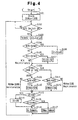
- the computer 81 performs various initialization steps in accordance with an initial program.
- the duty ratio Dt is initially set to 0%
- the upper limit value DtMax of the duty ratio Dt is set to 100%.
- the magnitude of the electronic force F that is, the set differential pressure, which is used to adjust the valve opening degree of the control valve 46
- the upper limit value DtMax is changed between 100% and a value less than 100%, for example, 40 - 60% (50% in the present embodiment). Setting the upper limit value DtMax to 50% limits the cooling capability of the air conditioner,
- step S102 the ON/OFF state of the A/C switch 83 is monitored until the A/C switch 83 is turned ON.
- step S103 the computer 81 determines the cooling state of the evaporator 38 based on the set temperature information from the temperature setting unit 85 or the temperature information from the compartment air temperature sensor 84.
- a target temperature Te(set) of the evaporator air temperature Te(t) is calculated in the range of 3 - 12 °C. Accordingly, the compartment air temperature sensor 84 and the temperature setting unit 85, together with the computer 81, form a temperature setting device for setting the target temperature the target temperature Te(set).
- step S104 the computer 81 determines whether the temperature Te(t) detected by the evaporator air temperature sensor 86 is greater than the target temperature Te(set). If the determination of the step S104 is NO, the computer 81 determines in step S105 whether the detected temperature Te(t) is less than the target temperature Te(set). If the determination of step S105 is also NO, since the detected temperature Te(t) is equal to the target temperature Te(set), the duty ratio Dt is not changed.
- step S104 If the determination of step S104 is YES, the computer 81 increases the duty ratio Dt by the unit amount ⁇ D in step S106.
- the driving signal Dt+ ⁇ D is output from the driving circuit 82 to the coil 75 of the control valve 46 as described above, the flow rate of the refrigerant in the refrigerant circulator is increased, and the cooling performance of the evaporator 38 increases, and the evaporator air temperature Te(t) decreases.
- step S105 If the determination of step S105 is YES, the computer 81 decreases the duty ratio Dt by the unit amount ⁇ D in step S107.
- the computer 81 determines whether the temperature Te(t) detected by the evaporator air temperature sensor 86 is outside of a predetermined threshold temperature range (for example, 15 - 16°C) and, if so, changes the upper limit value DtMax of the duty ratio Dt.
- the threshold temperature range (15 - 16°C) is greater than the set range (3 - 12°C) of the target temperature Te(set).
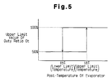
- step S108 the computer 81 determines whether the present set upper limit value DtMax is 100% or 50%. If the upper limit value DtMax is determined to 100% in step S108, the computer determines in step S109 whether the temperature Te(t) detected by the evaporator air temperature sensor 86 is less than the lower limit temperature (15 °C) of the threshold temperature range (15 - 16°C). If the determination of step S109 is NO, the upper limit value remains at 100%. On the contrary, if the determination of step S109 is YES, the upper limit value DtMax is changed from 100% to 50% in step S110.
- step S111 determines whether the temperature Te(t) detected by the evaporator air temperature sensor 86 is greater than the upper limit temperature (16°C) of the threshold temperature range (15 - 16°C). If the determination of step S111 is NO, the upper limit value DtMax remains at 50%. On the contrary, if the determination of step S111 is YES, the upper limit value DtMax is changed from 50% to 100%.
- Fig. 5 graphically shows the processes of steps S108 - S112, That is, if the temperature Te(t) detected by the evaporator air temperature sensor 86 falls from a temperature greater than the lower limit temperature (15°C) of the threshold temperature range (15 - 16°C) to a temperature less than the lower limit temperature (15°C), the computer 81 changes the upper limit value DtMax of the duty ratio Dt from 100% to 50%.
- the computer 81 determines the need for cooling by comparing the temperature Te(t) detected by the evaporator air temperature sensor 86 with the target temperature Te(set) and determines the degree of the cooling load by comparing the detected temperature Te(t) to a limit of the threshold temperature range (15 - 16°C).
- the computer determines that there is little or no need for cooling and reduces the upper limit value of the cooling capability.
- the computer determines that the need for cooling is large, and maximizes the cooling capability of the air conditioner by changing the upper limit value of the cooling capability.
- step S113 the computer 81 determines whether the duty ratio Dt calculated by steps S104 - S107 is less than 0%. If the determination of step S113 is YES, the computer 81 corrects the duty ratio Dt to 0% in step S114. Further, if the determination of step S113 is NO, the computer 81 determines in step S115 whether the duty ratio Dt calculated by steps S104 - 107 is greater than the upper limit value DtMax, which may have been re-set by steps S108 - 112. If the determination of step S115 is NO, the computer 81 sends the duty ratio Dt calculated by steps S104 - S107 to the driving circuit 82 in step S116. On the contrary, if the determination of step S115 is YES, the computer 81 sends the upper limit value DtMax to the driving circuit 82 in step S117.
- step S115 monitors whether the target differential pressure, which is calculated by steps S104 - S107, in the form of the duty ratio, is greater than the upper limit value. However, when the upper limit value DtMax is set to 100%, step S115 monitors only whether the duty ratio Dt is greater than the real range (0 - 100%) of the driving signal output from the driving circuit 82. For example, if a duty ratio Dt greater than 100% is sent to the driving circuit 82, the set differential pressure is set to the maximum value as when the duty ratio is 100%.
- the control valve 46 is designed to have a high cooling performance rather than high efficiency during those times.
- the control valve 46 is designed such that the compressor has the maximum discharge capacity and the differential pressure between two points ⁇ Pd resulted from the region where the rotating speed of the automotive engine Eg is high is set to the maximum value of the set differential pressure.
- the discharge capacity is the maximum value
- the discharge capacity of the compressor must be the maximum if the duty ratio Dt becomes 100%. Therefore, the air conditioner can exhibit the maximum cool capability at that time regardless of the rotating speed of the automotive engine Eg, and can cope with the high cooling load sufficiently.
- the automotive air conditioner of the present embodiment did not performed steps S108 - S117 to increase the cooling performance, the following problem occurs. If the air temperature at the evaporator Te(t) is less than the lower limit of the threshold temperature range (15 - 16°C), the cooling load decreases and the air temperature at the evaporator Te(t) is decreased to the target temperature Te(set). Therefore, there is no need for the maximum cooling capability at that time.
- a duty ratio Dt of 100% is always allowed. Accordingly, though the air temperature at the evaporator Te(t) is decrease to the vicinity of the target temperature Te(set) and the cooling load is small, there is a problem that the duty ratio Dt may be set to 100% continuously until the air temperature at the evaporator Te(t) is less than the target temperature Te(set). If the duty ratio Dt is set to 100%, when the rotating speed of the automotive engine Eg becomes very high speed region, the discharge capacity of the compressor is maximized by the control valve 46, and the cooling capability continuously maximized. In other words, the compressor is unnecessarily in a high load and inefficient state.
- steps S108 - S112 are performed, if the air temperature at the evaporator Te(t) is less than the lower limit of the threshold temperature range (15 - 16°C), the cooling load is determined to be small, and the duty ratio Dt is set to 50%, even though the air temperature of the evaporator Te(t) has not reached the target temperature Te(set). Accordingly, when the air temperature at the evaporator Te(t) is less than the lower limit of the threshold temperature range (15 - 16°C), the target differential pressure does not exceed an upper limit value that corresponds to the duty ratio Dt of 50%.
- the set differential pressure (the duty ratio) is set to the upper limit value
- the differential pressure ⁇ Pd will exceed the upper limit value of the target differential pressure when the discharge capacity reaches the maximum value that corresponds to the upper limit value of 50%, and consequently the discharge capacity of the compressor is automatically reduced by the control valve 46.
- the compressor avoids a low efficiency and high load state, the operating efficiency of the automotive engine Eg is improved, and fuel consumption is reduced. Also, the compressor can be protected and used for a long time.
- the size of the cooling unit for cooling the engine can be reduced.
- a control valve 46 includes an operating rod 53, which is urged by a force based on a differential pressure PdH-PdL between two pressure monitoring points P1, P2, which are located in a refrigeration circuit.
- the control valve causes the compressor to seek a target displacement.
- a computer limits the target displacement when the demand for cooling is decreasing to improve fuel economy and to extend the life of the compressor.
Landscapes
- Engineering & Computer Science (AREA)
- Mechanical Engineering (AREA)
- General Engineering & Computer Science (AREA)
- Computer Hardware Design (AREA)
- Compressors, Vaccum Pumps And Other Relevant Systems (AREA)
- Control Of Positive-Displacement Pumps (AREA)
- Air-Conditioning For Vehicles (AREA)
Applications Claiming Priority (2)
| Application Number | Priority Date | Filing Date | Title |
|---|---|---|---|
| JP2000029549 | 2000-02-07 | ||
| JP2000029549A JP3797055B2 (ja) | 2000-02-07 | 2000-02-07 | 可変容量型圧縮機の制御装置 |
Publications (2)
| Publication Number | Publication Date |
|---|---|
| EP1122431A2 true EP1122431A2 (fr) | 2001-08-08 |
| EP1122431A3 EP1122431A3 (fr) | 2003-06-18 |
Family
ID=18554794
Family Applications (1)
| Application Number | Title | Priority Date | Filing Date |
|---|---|---|---|
| EP01102570A Withdrawn EP1122431A3 (fr) | 2000-02-07 | 2001-02-06 | Circuit de commande d'un compresseur à capacité variable |
Country Status (6)
| Country | Link |
|---|---|
| US (1) | US6453685B2 (fr) |
| EP (1) | EP1122431A3 (fr) |
| JP (1) | JP3797055B2 (fr) |
| KR (1) | KR100360520B1 (fr) |
| CN (1) | CN1161546C (fr) |
| BR (1) | BR0100756A (fr) |
Cited By (1)
| Publication number | Priority date | Publication date | Assignee | Title |
|---|---|---|---|---|
| FR2853019A1 (fr) * | 2003-03-28 | 2004-10-01 | Sanden Corp | Dispositif de compression a plateau oscillant d'un type a capacite variable |
Families Citing this family (31)
| Publication number | Priority date | Publication date | Assignee | Title |
|---|---|---|---|---|
| JP3735512B2 (ja) * | 2000-05-10 | 2006-01-18 | 株式会社豊田自動織機 | 容量可変型圧縮機の制御弁 |
| JP4081965B2 (ja) * | 2000-07-07 | 2008-04-30 | 株式会社豊田自動織機 | 容量可変型圧縮機の容量制御機構 |
| JP2002285956A (ja) * | 2000-08-07 | 2002-10-03 | Toyota Industries Corp | 容量可変型圧縮機の制御弁 |
| JP2002081374A (ja) * | 2000-09-05 | 2002-03-22 | Toyota Industries Corp | 容量可変型圧縮機の制御弁 |
| JP2002089442A (ja) * | 2000-09-08 | 2002-03-27 | Toyota Industries Corp | 容量可変型圧縮機の制御弁 |
| JP2002155858A (ja) * | 2000-09-08 | 2002-05-31 | Toyota Industries Corp | 容量可変型圧縮機の制御弁 |
| KR100899609B1 (ko) * | 2000-12-28 | 2009-05-27 | 도쿄엘렉트론가부시키가이샤 | 기판처리장치 및 기판처리방법 |
| JP4333047B2 (ja) * | 2001-01-12 | 2009-09-16 | 株式会社豊田自動織機 | 容量可変型圧縮機の制御弁 |
| JP4926343B2 (ja) * | 2001-08-08 | 2012-05-09 | サンデン株式会社 | 圧縮機の容量制御装置 |
| JP4271459B2 (ja) * | 2002-05-15 | 2009-06-03 | サンデン株式会社 | 空調装置 |
| JP2004060644A (ja) * | 2002-06-05 | 2004-02-26 | Denso Corp | 圧縮機装置およびその制御方法 |
| JP2005037093A (ja) * | 2003-07-18 | 2005-02-10 | Tgk Co Ltd | 冷凍サイクル |
| JP2006083837A (ja) * | 2004-08-19 | 2006-03-30 | Tgk Co Ltd | 可変容量圧縮機用制御弁 |
| US20070064665A1 (en) | 2005-08-23 | 2007-03-22 | Interdigital Technology Corporation | Method and apparatus for accessing an uplink random access channel in a single carrier frequency division multiple access system |
| JP2007163074A (ja) * | 2005-12-15 | 2007-06-28 | Denso Corp | 冷凍サイクル |
| US7611335B2 (en) * | 2006-03-15 | 2009-11-03 | Delphi Technologies, Inc. | Two set-point pilot piston control valve |
| ITTO20060203A1 (it) * | 2006-03-17 | 2007-09-18 | Fiat Ricerche | Sistema e metodo di controllo di un impianto di climatizzazione di un veicolo a ridotto consumo energetico |
| JP5012193B2 (ja) * | 2006-06-06 | 2012-08-29 | 株式会社デンソー | 車両用空調装置 |
| US7705977B2 (en) * | 2006-12-21 | 2010-04-27 | Kla-Tencor Corporation | Methods for depth profiling in semiconductors using modulated optical reflectance technology |
| JP4861914B2 (ja) | 2007-06-26 | 2012-01-25 | サンデン株式会社 | 可変容量圧縮機の容量制御システム |
| US20090242652A1 (en) * | 2008-03-25 | 2009-10-01 | Denso International America, Inc. | Power saving compressor and control logic |
| US8719909B2 (en) * | 2008-04-01 | 2014-05-06 | Yougetitback Limited | System for monitoring the unauthorized use of a device |
| KR101149206B1 (ko) | 2008-09-25 | 2012-05-25 | 한라공조주식회사 | 자동차용 공조장치의 압축기 제어방법 |
| US8484985B2 (en) * | 2009-03-31 | 2013-07-16 | Delphi Technologies, Inc. | Air conditioner system having an externally controlled variable displacement compressor and a clutch and method of operating the same |
| JP5624825B2 (ja) * | 2010-07-29 | 2014-11-12 | 株式会社日立ハイテクノロジーズ | 液体クロマトグラフ用ポンプ、および液体クロマトグラフ |
| KR20140144843A (ko) | 2013-06-12 | 2014-12-22 | 주식회사 엘지화학 | 실링부가 경화성 물질로 절연되어 있는 파우치형 전지셀의 제조방법 |
| CN106368939B (zh) * | 2016-08-30 | 2017-09-12 | 东风柳州汽车有限公司 | 汽车空调电动压缩机转速控制方法 |
| CN108116183B (zh) * | 2016-11-28 | 2024-03-12 | 杭州三花研究院有限公司 | 一种热管理系统的控制方法 |
| EP3730787B1 (fr) * | 2019-04-24 | 2025-12-24 | TE Connectivity Germany GmbH | Dispositif de commande pour compresseur, compresseur le comprenant et système de conditionnement d'air comprenant le dispositif de commande et le compresseur |
| US10670003B1 (en) * | 2019-10-24 | 2020-06-02 | CW Holdings Ltd. | Tilt linkage for variable stroke pump |
| CN113635736B (zh) * | 2021-09-14 | 2023-04-14 | 东风汽车集团股份有限公司 | 一种汽车热管理系统压缩机压力保护控制方法 |
Family Cites Families (6)
| Publication number | Priority date | Publication date | Assignee | Title |
|---|---|---|---|---|
| AU615200B2 (en) * | 1987-06-30 | 1991-09-26 | Sanden Corporation | Refrigerant circuit with passageway control mechanism |
| US5189886A (en) * | 1987-09-22 | 1993-03-02 | Sanden Corporation | Refrigerating system having a compressor with an internally and externally controlled variable displacement mechanism |
| JP3178631B2 (ja) * | 1993-01-11 | 2001-06-25 | 株式会社豊田自動織機製作所 | 可変容量型圧縮機用制御弁 |
| JPH06341378A (ja) | 1993-06-03 | 1994-12-13 | Tgk Co Ltd | 容量可変圧縮機の容量制御装置 |
| JP3355002B2 (ja) * | 1993-10-15 | 2002-12-09 | 株式会社豊田自動織機 | 可変容量型圧縮機用制御弁 |
| US6010312A (en) * | 1996-07-31 | 2000-01-04 | Kabushiki Kaisha Toyoda Jidoshokki Seiksakusho | Control valve unit with independently operable valve mechanisms for variable displacement compressor |
-
2000
- 2000-02-07 JP JP2000029549A patent/JP3797055B2/ja not_active Expired - Fee Related
-
2001
- 2001-02-06 CN CNB01111925XA patent/CN1161546C/zh not_active Expired - Fee Related
- 2001-02-06 EP EP01102570A patent/EP1122431A3/fr not_active Withdrawn
- 2001-02-06 US US09/777,596 patent/US6453685B2/en not_active Expired - Fee Related
- 2001-02-06 BR BR0100756-4A patent/BR0100756A/pt not_active IP Right Cessation
- 2001-02-07 KR KR1020010005974A patent/KR100360520B1/ko not_active Expired - Fee Related
Cited By (2)
| Publication number | Priority date | Publication date | Assignee | Title |
|---|---|---|---|---|
| FR2853019A1 (fr) * | 2003-03-28 | 2004-10-01 | Sanden Corp | Dispositif de compression a plateau oscillant d'un type a capacite variable |
| US7371054B2 (en) | 2003-03-28 | 2008-05-13 | Sanden Corporation | Swash-plate compression device of variable capacity type |
Also Published As
| Publication number | Publication date |
|---|---|
| CN1161546C (zh) | 2004-08-11 |
| US20010027659A1 (en) | 2001-10-11 |
| BR0100756A (pt) | 2001-09-11 |
| CN1318694A (zh) | 2001-10-24 |
| EP1122431A3 (fr) | 2003-06-18 |
| US6453685B2 (en) | 2002-09-24 |
| JP2001213153A (ja) | 2001-08-07 |
| JP3797055B2 (ja) | 2006-07-12 |
| KR100360520B1 (ko) | 2002-11-13 |
| KR20010078364A (ko) | 2001-08-20 |
Similar Documents
| Publication | Publication Date | Title |
|---|---|---|
| US6453685B2 (en) | Control apparatus and control method for variable displacement compressor | |
| US6434956B1 (en) | Control valve and method for controlling an air-conditioning system | |
| EP1127721B1 (fr) | Appareil et procédé de réglage du déplacement d'un compresseur à déplacement variable et module de compresseur | |
| EP1172559B1 (fr) | Système de contrôle pour un compresseur à plateau en biais à capacité variable | |
| US6371734B1 (en) | Control valve for variable displacement compressor | |
| US6385982B1 (en) | Air conditioning apparatus | |
| US6385979B2 (en) | Displacement control apparatus and method for variable displacement compressor | |
| US6389824B2 (en) | Controller for variable displacement compressor | |
| US6382926B2 (en) | Control valve in variable displacement compressor | |
| US6508071B2 (en) | Air conditioner and displacement control valve for variable displacement compressor | |
| US20010055531A1 (en) | Control valve for variable displacement compressor | |
| KR100494210B1 (ko) | 용량가변형 압축기의 제어밸브 | |
| US6672844B2 (en) | Apparatus and method for controlling variable displacement compressor | |
| US6519960B2 (en) | Air conditioner | |
| US6524077B2 (en) | Control valve for variable displacement compressor | |
| US6520749B2 (en) | Control valve for variable displacement compressor | |
| US6578372B2 (en) | Apparatus and method for controlling variable displacement compressor | |
| US6510702B2 (en) | Control valve for variable displacement compressor | |
| US20020152763A1 (en) | Control device of variable displacement compressor |
Legal Events
| Date | Code | Title | Description |
|---|---|---|---|
| PUAI | Public reference made under article 153(3) epc to a published international application that has entered the european phase |
Free format text: ORIGINAL CODE: 0009012 |
|
| 17P | Request for examination filed |
Effective date: 20010206 |
|
| AK | Designated contracting states |
Kind code of ref document: A2 Designated state(s): AT BE CH CY DE DK ES FI FR GB GR IE IT LI LU MC NL PT SE TR |
|
| AX | Request for extension of the european patent |
Free format text: AL;LT;LV;MK;RO;SI |
|
| RAP1 | Party data changed (applicant data changed or rights of an application transferred) |
Owner name: KABUSHIKI KAISHA TOYOTA JIDOSHOKKI |
|
| PUAL | Search report despatched |
Free format text: ORIGINAL CODE: 0009013 |
|
| AK | Designated contracting states |
Designated state(s): AT BE CH CY DE DK ES FI FR GB GR IE IT LI LU MC NL PT SE TR |
|
| AX | Request for extension of the european patent |
Extension state: AL LT LV MK RO SI |
|
| AKX | Designation fees paid |
Designated state(s): DE FR IT SE |
|
| STAA | Information on the status of an ep patent application or granted ep patent |
Free format text: STATUS: THE APPLICATION IS DEEMED TO BE WITHDRAWN |
|
| 18D | Application deemed to be withdrawn |
Effective date: 20060521 |