EP1122453A1 - Bremssattel für eine Scheibenbremse und zugehöriges Herstellungsverfahren - Google Patents
Bremssattel für eine Scheibenbremse und zugehöriges Herstellungsverfahren Download PDFInfo
- Publication number
- EP1122453A1 EP1122453A1 EP00830066A EP00830066A EP1122453A1 EP 1122453 A1 EP1122453 A1 EP 1122453A1 EP 00830066 A EP00830066 A EP 00830066A EP 00830066 A EP00830066 A EP 00830066A EP 1122453 A1 EP1122453 A1 EP 1122453A1
- Authority
- EP
- European Patent Office
- Prior art keywords
- callipers
- calliper
- welding
- body according
- calliper body
- Prior art date
- Legal status (The legal status is an assumption and is not a legal conclusion. Google has not performed a legal analysis and makes no representation as to the accuracy of the status listed.)
- Withdrawn
Links
- 238000004519 manufacturing process Methods 0.000 title description 3
- 238000003466 welding Methods 0.000 claims abstract description 48
- 238000000034 method Methods 0.000 claims abstract description 23
- 238000003754 machining Methods 0.000 claims abstract description 8
- 238000010894 electron beam technology Methods 0.000 claims abstract description 6
- 238000003756 stirring Methods 0.000 claims abstract description 3
- 239000000463 material Substances 0.000 claims description 24
- 238000007667 floating Methods 0.000 claims description 5
- 229910052751 metal Inorganic materials 0.000 claims description 5
- 239000002184 metal Substances 0.000 claims description 5
- 239000002131 composite material Substances 0.000 claims description 4
- 239000011159 matrix material Substances 0.000 claims description 3
- 229910000838 Al alloy Inorganic materials 0.000 claims description 2
- 238000005266 casting Methods 0.000 claims 1
- 238000004512 die casting Methods 0.000 abstract description 6
- 238000006243 chemical reaction Methods 0.000 description 6
- 238000010586 diagram Methods 0.000 description 5
- 239000000945 filler Substances 0.000 description 3
- XKRFYHLGVUSROY-UHFFFAOYSA-N Argon Chemical compound [Ar] XKRFYHLGVUSROY-UHFFFAOYSA-N 0.000 description 2
- 239000012530 fluid Substances 0.000 description 2
- 230000004927 fusion Effects 0.000 description 2
- 238000010438 heat treatment Methods 0.000 description 2
- 239000011261 inert gas Substances 0.000 description 2
- 150000002500 ions Chemical class 0.000 description 2
- 229910001234 light alloy Inorganic materials 0.000 description 2
- 230000000452 restraining effect Effects 0.000 description 2
- 229910001018 Cast iron Inorganic materials 0.000 description 1
- 229910001208 Crucible steel Inorganic materials 0.000 description 1
- FYYHWMGAXLPEAU-UHFFFAOYSA-N Magnesium Chemical compound [Mg] FYYHWMGAXLPEAU-UHFFFAOYSA-N 0.000 description 1
- 229910000861 Mg alloy Inorganic materials 0.000 description 1
- 229910000676 Si alloy Inorganic materials 0.000 description 1
- XUIMIQQOPSSXEZ-UHFFFAOYSA-N Silicon Chemical compound [Si] XUIMIQQOPSSXEZ-UHFFFAOYSA-N 0.000 description 1
- 239000004411 aluminium Substances 0.000 description 1
- 229910052782 aluminium Inorganic materials 0.000 description 1
- XAGFODPZIPBFFR-UHFFFAOYSA-N aluminium Chemical compound [Al] XAGFODPZIPBFFR-UHFFFAOYSA-N 0.000 description 1
- 229910052786 argon Inorganic materials 0.000 description 1
- 230000000740 bleeding effect Effects 0.000 description 1
- 230000000295 complement effect Effects 0.000 description 1
- 230000006835 compression Effects 0.000 description 1
- 238000007906 compression Methods 0.000 description 1
- 239000006185 dispersion Substances 0.000 description 1
- 238000009826 distribution Methods 0.000 description 1
- 230000005489 elastic deformation Effects 0.000 description 1
- 238000005516 engineering process Methods 0.000 description 1
- 238000003780 insertion Methods 0.000 description 1
- 230000037431 insertion Effects 0.000 description 1
- 238000005304 joining Methods 0.000 description 1
- 239000011777 magnesium Substances 0.000 description 1
- 230000002093 peripheral effect Effects 0.000 description 1
- 230000001105 regulatory effect Effects 0.000 description 1
- 239000011150 reinforced concrete Substances 0.000 description 1
- 230000000717 retained effect Effects 0.000 description 1
- 238000010079 rubber tapping Methods 0.000 description 1
- 238000007789 sealing Methods 0.000 description 1
- 239000010703 silicon Substances 0.000 description 1
- 239000010959 steel Substances 0.000 description 1
- 238000009827 uniform distribution Methods 0.000 description 1
- 239000011800 void material Substances 0.000 description 1
Images

Classifications
-
- F—MECHANICAL ENGINEERING; LIGHTING; HEATING; WEAPONS; BLASTING
- F16—ENGINEERING ELEMENTS AND UNITS; GENERAL MEASURES FOR PRODUCING AND MAINTAINING EFFECTIVE FUNCTIONING OF MACHINES OR INSTALLATIONS; THERMAL INSULATION IN GENERAL
- F16D—COUPLINGS FOR TRANSMITTING ROTATION; CLUTCHES; BRAKES
- F16D55/00—Brakes with substantially-radial braking surfaces pressed together in axial direction, e.g. disc brakes
- F16D55/02—Brakes with substantially-radial braking surfaces pressed together in axial direction, e.g. disc brakes with axially-movable discs or pads pressed against axially-located rotating members
- F16D55/22—Brakes with substantially-radial braking surfaces pressed together in axial direction, e.g. disc brakes with axially-movable discs or pads pressed against axially-located rotating members by clamping an axially-located rotating disc between movable braking members, e.g. movable brake discs or brake pads
- F16D55/228—Brakes with substantially-radial braking surfaces pressed together in axial direction, e.g. disc brakes with axially-movable discs or pads pressed against axially-located rotating members by clamping an axially-located rotating disc between movable braking members, e.g. movable brake discs or brake pads with a separate actuating member for each side
-
- F—MECHANICAL ENGINEERING; LIGHTING; HEATING; WEAPONS; BLASTING
- F16—ENGINEERING ELEMENTS AND UNITS; GENERAL MEASURES FOR PRODUCING AND MAINTAINING EFFECTIVE FUNCTIONING OF MACHINES OR INSTALLATIONS; THERMAL INSULATION IN GENERAL
- F16D—COUPLINGS FOR TRANSMITTING ROTATION; CLUTCHES; BRAKES
- F16D55/00—Brakes with substantially-radial braking surfaces pressed together in axial direction, e.g. disc brakes
- F16D2055/0004—Parts or details of disc brakes
- F16D2055/0016—Brake calipers
-
- F—MECHANICAL ENGINEERING; LIGHTING; HEATING; WEAPONS; BLASTING
- F16—ENGINEERING ELEMENTS AND UNITS; GENERAL MEASURES FOR PRODUCING AND MAINTAINING EFFECTIVE FUNCTIONING OF MACHINES OR INSTALLATIONS; THERMAL INSULATION IN GENERAL
- F16D—COUPLINGS FOR TRANSMITTING ROTATION; CLUTCHES; BRAKES
- F16D55/00—Brakes with substantially-radial braking surfaces pressed together in axial direction, e.g. disc brakes
- F16D2055/0004—Parts or details of disc brakes
- F16D2055/0016—Brake calipers
- F16D2055/002—Brake calipers assembled from a plurality of parts
-
- F—MECHANICAL ENGINEERING; LIGHTING; HEATING; WEAPONS; BLASTING
- F16—ENGINEERING ELEMENTS AND UNITS; GENERAL MEASURES FOR PRODUCING AND MAINTAINING EFFECTIVE FUNCTIONING OF MACHINES OR INSTALLATIONS; THERMAL INSULATION IN GENERAL
- F16D—COUPLINGS FOR TRANSMITTING ROTATION; CLUTCHES; BRAKES
- F16D55/00—Brakes with substantially-radial braking surfaces pressed together in axial direction, e.g. disc brakes
- F16D2055/0075—Constructional features of axially engaged brakes
- F16D2055/0091—Plural actuators arranged side by side on the same side of the rotor
-
- F—MECHANICAL ENGINEERING; LIGHTING; HEATING; WEAPONS; BLASTING
- F16—ENGINEERING ELEMENTS AND UNITS; GENERAL MEASURES FOR PRODUCING AND MAINTAINING EFFECTIVE FUNCTIONING OF MACHINES OR INSTALLATIONS; THERMAL INSULATION IN GENERAL
- F16D—COUPLINGS FOR TRANSMITTING ROTATION; CLUTCHES; BRAKES
- F16D2200/00—Materials; Production methods therefor
- F16D2200/0004—Materials; Production methods therefor metallic
- F16D2200/0026—Non-ferro
- F16D2200/003—Light metals, e.g. aluminium
-
- F—MECHANICAL ENGINEERING; LIGHTING; HEATING; WEAPONS; BLASTING
- F16—ENGINEERING ELEMENTS AND UNITS; GENERAL MEASURES FOR PRODUCING AND MAINTAINING EFFECTIVE FUNCTIONING OF MACHINES OR INSTALLATIONS; THERMAL INSULATION IN GENERAL
- F16D—COUPLINGS FOR TRANSMITTING ROTATION; CLUTCHES; BRAKES
- F16D2250/00—Manufacturing; Assembly
- F16D2250/0007—Casting
-
- F—MECHANICAL ENGINEERING; LIGHTING; HEATING; WEAPONS; BLASTING
- F16—ENGINEERING ELEMENTS AND UNITS; GENERAL MEASURES FOR PRODUCING AND MAINTAINING EFFECTIVE FUNCTIONING OF MACHINES OR INSTALLATIONS; THERMAL INSULATION IN GENERAL
- F16D—COUPLINGS FOR TRANSMITTING ROTATION; CLUTCHES; BRAKES
- F16D2250/00—Manufacturing; Assembly
- F16D2250/0061—Joining
- F16D2250/0076—Welding, brazing
Definitions
- the present invention relates to a calliper body for disc brakes and the corresponding method of production.
- calliper bodies for disc brakes regardless of whether they are of the fixed type, in other words those having opposing hydraulic pistons, or of the floating type, in other words those having pistons on only one arm of the calliper, consist of two separate half-callipers, which are locked together by means of screws or bolts which have to be positioned at the periphery of the disc, in order not to interfere with the disc.
- the calliper body has to be made in the form of two separate half-callipers, formed by die-casting, because of the requirements of machining to produce housings which are dimensionally accurate, with limited tolerances, for the hydraulic pistons and their sealing members, as well as housings for the brake pads.
- connection of the two half-callipers by means of screws requires particularly precise, and therefore expensive, machining of the housings and of the threaded parts, and, obviously, of the contact surface of the two half-callipers.
- the problem upon which the present invention is based is that of devising a calliper body for disc brakes which has structural and functional characteristics such that the problems and disadvantages referred to above are overcome.
- the one-piece calliper body makes it possible to provide a one-piece calliper for disc brakes, which has reduced overall dimensions, which reduces the quantity of material used and which reduces to a minimum the complexity and difficulties of assembly and the corresponding cost, but which is also reliable.
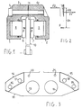
- Figure 1 shows schematically a conventional calliper, in a section perpendicular to the plane of the brake disc.
- This calliper consists of two half-callipers 1 and 2, formed by die-casting, juxtaposed at the positions of two yokes 3 and 4 (otherwise called “bridges"), and having flat contact surfaces.
- the yokes 3 and 4 are locked against each other by means of screws 5 housed in housings (some of which are threaded) formed suitably in the yokes 3 and 4.
- the yokes 3 and 4 in order not to interfere with the disc 10, must be positioned at the periphery of the disc 10, with a certain radial dimensions which is additional to that of the disc, while the hydraulic pistons must act on the peripheral rim of the disc surface.
- the restraining reaction in the section A-A must be equivalent to a tensile force exerted between the yokes and a moment.
- the only stress which can be exerted between the yokes is a compressive stress, while the tensile force can be opposed only by the screws 5.
- the unit stress in the cross-section of the screws has a uniform distribution and can be represented by the resultant F1 centred on the axis of each screw, in order to ensure the continuity of the material subjected to elastic deformation and the flatness of the surface, the unit compressive stress on the contact surface between the yokes 3 and 4 must have a triangular distribution (as shown in Fig. 2), with a resultant F2 relatively close to F1 (distance D2) with respect to the distance D1 between the application straight line F1 and the line F.
- F2xD2 FxD1 and consequently F2 must be much greater than F and the value of
- the half-calliper consists of a body 11, formed by die-casting, in which one or more cylindrical chambers 12, 13, for housing the hydraulic pistons of the brake, are formed by machining.
- the half-calliper is provided with two connecting yokes 14, 15, spaced apart from each other and generally in the shape of sectors of circular rims, having flat surfaces for connection to a second half-calliper which is similar to, and a mirror image of, that which is shown.
- One of the two half-callipers is provided with lugs (not shown) for fixing the calliper body to fixed parts of the equipment on which the brake is to be fitted, this equipment being generally, but not necessarily, a vehicle.
- the connecting yokes 14, 15 are provided with cylindrical housings 16, 17, 18, 19 (threaded in one of the two opposing half-callipers) for the insertion of locking screws.
- the housings for the screws are conveniently placed as close as possible to the radially inner edge (with reference to the axis of the disc) of the contact surface of the yokes, to increase the resisting moment of the cross-section (in other words, increasing D2 as much as possible) while containing the tensile stress in the screws and the compressive stress in the yokes within acceptable limits.
- the radial dimension of the yokes is considerable.
- the radial thickness of the yokes is of the order of 20-25 mm.
- the void between the two yokes 14, 15 is conveniently used, when the calliper has been assembled, for easy replacement of the brake pads which are then retained in their housings by convenient locking devices, such as pins passing into the pads and into suitable housings 20 and 21 formed in the half-callipers by machining.
- Figure 4 shows schematically in cross section, for comparison with Figure 1, a one-piece calliper made by welding two half-callipers, according to the present invention.
- the calliper of Figure 4 differs from that of Figure 1 only in the radial thickness of the yokes 3 and 4, which is conveniently reduced (by as much as 25%) and in the absence of locking screws and of the corresponding threaded housings formed in the yokes of the half-callipers.
- the one-piece structure of the calliper body is obtained by welding together the yokes 3 and 4, by appropriate methods, along the contact surface A-A.
- the force F which tends to spread the arms of the calliper apart subjects the material in the section A-A to unit tensile and compressive stresses distributed in the section according to a triangular diagram such as that shown in Figure 5, in which the tensile stresses are greater than the compressive stresses (giving as a resultant a moment plus a force equal and opposed to F) without causing the unit stresses to reach unacceptable values for the material, since the tensile force is distributed over a useful cross section which is much greater than that of the screws or bolts of a conventional calliper. This is true even if the radial thickness of the yokes is smaller than that of a conventional calliper having the same specifications.
- the resultant F1S of the unit tensile stresses is closer to the straight line of application of F than in the case shown in Figure 2 (in other words, D1S ⁇ D1)
- the resultant F2S of the unit compressive stresses is farther from the straight line of application of F1S than in the case shown in Figure 2 (in other words, D2S > D2), so that both F1S and F2S are significantly smaller than the reactions F1, F2 developed in the case shown in Figure 2.
- the first is that, since only the radially inner part of the section (with reference to the axis of the disc) is subjected to tension, the weld can be limited to this part of the yokes only.
- the yokes can conveniently be grooved, or hollowed, in their radially median parts, with consequent redistribution of the unit stresses in the cross section which makes them more uniform without an appreciable increase in the maximum stress.
- the one-piece body of the calliper according to the present invention can have the configuration shown in Figure 6, in which the common constructional details are identified by the same numerical references as those of Figure 4.
- the one-piece calliper of Figure 6 differs from that of Figure 4 in the presence in the two yokes 3 and 4 of a toroidal groove 22, so that the contact surface between the two yokes 3 and 4 is reduced to two sectors of concentric circular rims 23 and 24 spaced apart radially by the cavity 22 interposed between them.
- a further difference consists in the fact that, if necessary, the yokes can be welded together only at the inner circular sector 24, so that the welding operations are simplified and made easier and faster, particularly if methods are used in which the welding depth is a critical limiting factor.
- Each half-calliper like that of Figure 3, is provided with a pair of yokes 25 and 26, each having its surface for contact with the conjugate half-calliper divided into two sectors of concentric circular rims, indicated by 27 and 28 and by 29 and 30 respectively, separated by two interposed grooves 31 and 32 respectively.
- the two half-callipers can be welded by using the various methods recently developed for welding light alloys of aluminium, silicon and magnesium, and even more suitable for use with different materials, such as cast iron, steel and composite materials in metal matrices.
- the welding therefore induces minimal internal stresses and does not cause significant deformations of the welded elements.
- a first method is known as electron beam welding or EBW: a precisely focused electron beam is generated, consisting of electrons accelerated to very high velocities, up to as much as 66% of the speed of light.
- the beam is directed on to the section to be welded and made to move parallel to it, causing it to be gradually fused and welded.
- the prerequisite of this method is the capacity to operate in a vacuum, to prevent the dispersion of the electron beam caused by impact of the electrons with the molecules of the atmosphere or of an inert gas.
- a similar welding method which does not require operation in a vacuum is known as plasma welding: in this case, a beam of ions is generated, preferably ions of an inert gas such as argon, which, as in the case of the electrons, act as an energy carrier and therefore as a concentrated and controllable heat source.
- a beam of ions is generated, preferably ions of an inert gas such as argon, which, as in the case of the electrons, act as an energy carrier and therefore as a concentrated and controllable heat source.
- this method which is particularly efficient, with a high welding speed, while also being economical both in terms of equipment and in terms of operation, is only limited, by comparison with the EBW technology, in that the welding depth cannot exceed 12-15 mm with the commercially available equipment.
- a third method which can be applied is what is called “stir friction welding", in which the localized heating with consequent plasticizing/fusion of the material is caused by the friction with a rotating pin which is sunk into the material and moved along the welding line.
- the maximum welding depth obtainable in one pass is 15 mm, and this can be doubled by working on two opposite sides of the section to be welded.
- the one-piece callipers obtained in this way can be made by using materials with different mechanical characteristics for the two half-callipers: for example, a floating calliper body can be formed with the reaction side, which does not require particularly accurate machining, in a composite material with a metal matrix, while the half-calliper with the piston housings, the supply channels, and the threaded connectors for hydraulic connections and bleeding can be made from more easily machinable aluminium alloy.
- the calliper body for disc brakes according to the invention makes it possible to produce a calliper for disc brakes which can overcome the problems mentioned with reference to the prior art brake callipers.
- a further advantage of the calliper body for disc brakes according to the invention resides in the novel structural and operational simplicity of the calliper which is, moreover, economical to produce by comparison with the prior art callipers. This is because the calliper body is assembled without the need to carry out operations of boring and tapping the calliper bodies for screw connection means, and the costs of screw connection means are avoided. It should also be pointed out that the welding operation is unquestionably easier to automate than the operations of centring screw connection means.
- Yet another advantage of the calliper body for disc brakes according to the invention resides in the fact that, in the case of callipers with internally formed channels for the passage of fluid between the two half-callipers, the weld joining the two half-callipers is in itself sufficient to provide the necessary tightness, without the use of seals.
- contact surface along which the welding between the two half-callipers is carried out does not have to be flat and does not have to be contained in one plane.
- the two half-callipers can be shaped in such a way as to have complementary projections and recesses (of a stepped type, for example) designed to be joined in contact with each other. This solution is particularly suitable for the embodiment of the brake calliper shown in Figure 6.
- the contact surface along which the welding between the two half-calliper is carried out can be located in a plane inclined with respect to the plane of the disc brake.
Landscapes
- Engineering & Computer Science (AREA)
- General Engineering & Computer Science (AREA)
- Mechanical Engineering (AREA)
- Braking Arrangements (AREA)
Priority Applications (3)
| Application Number | Priority Date | Filing Date | Title |
|---|---|---|---|
| EP00830066A EP1122453A1 (de) | 2000-01-31 | 2000-01-31 | Bremssattel für eine Scheibenbremse und zugehöriges Herstellungsverfahren |
| AU2001237331A AU2001237331A1 (en) | 2000-01-31 | 2001-01-23 | Calliper body for disc brakes |
| PCT/EP2001/000686 WO2001057413A1 (en) | 2000-01-31 | 2001-01-23 | Calliper body for disc brakes |
Applications Claiming Priority (1)
| Application Number | Priority Date | Filing Date | Title |
|---|---|---|---|
| EP00830066A EP1122453A1 (de) | 2000-01-31 | 2000-01-31 | Bremssattel für eine Scheibenbremse und zugehöriges Herstellungsverfahren |
Publications (1)
| Publication Number | Publication Date |
|---|---|
| EP1122453A1 true EP1122453A1 (de) | 2001-08-08 |
Family
ID=8175156
Family Applications (1)
| Application Number | Title | Priority Date | Filing Date |
|---|---|---|---|
| EP00830066A Withdrawn EP1122453A1 (de) | 2000-01-31 | 2000-01-31 | Bremssattel für eine Scheibenbremse und zugehöriges Herstellungsverfahren |
Country Status (3)
| Country | Link |
|---|---|
| EP (1) | EP1122453A1 (de) |
| AU (1) | AU2001237331A1 (de) |
| WO (1) | WO2001057413A1 (de) |
Cited By (4)
| Publication number | Priority date | Publication date | Assignee | Title |
|---|---|---|---|---|
| DE10200967A1 (de) * | 2002-01-12 | 2003-07-31 | Kurt Fuechtler | Scheibenbremse für eine Kraftfahrzeugbremsanlage |
| EP1688207A1 (de) * | 2005-02-07 | 2006-08-09 | Hitachi, Ltd. | Zylindervorrichtung und Scheibenbremse |
| EP1826448A1 (de) * | 2006-02-24 | 2007-08-29 | Hitachi, Ltd. | Scheibenbremse |
| US20250215944A1 (en) * | 2024-01-03 | 2025-07-03 | Ccys Hi-Tech International Ltd. | Brake caliper housing for friction stir welding |
Families Citing this family (1)
| Publication number | Priority date | Publication date | Assignee | Title |
|---|---|---|---|---|
| US20130048444A1 (en) | 2011-08-25 | 2013-02-28 | Shimano Inc. | Bicycle disc brake caliper |
Citations (6)
| Publication number | Priority date | Publication date | Assignee | Title |
|---|---|---|---|---|
| US3611988A (en) * | 1968-06-26 | 1971-10-12 | Girling Ltd | Parallel abutments and circumferentially extended pads |
| GB2131507A (en) * | 1982-12-07 | 1984-06-20 | Teves Gmbh Alfred | Brake caliper housing |
| DE4020669A1 (de) * | 1990-06-29 | 1992-01-02 | Teves Gmbh Alfred | Verfahren zur herstellung eines bremssattelgehaeuses |
| JPH05215157A (ja) * | 1992-02-06 | 1993-08-24 | Nissin Kogyo Kk | 車両用ディスクブレーキの分割型キャリパボディ |
| DE19647999A1 (de) * | 1996-11-20 | 1998-05-28 | Teves Gmbh Alfred | Bremssattel insbesondere für Kraftfahrzeuge |
| EP0919317A1 (de) * | 1996-07-11 | 1999-06-02 | Alexandr Ivanovich Apunevich | Verfahren zum plasmischen lichtbogenschweissen von metallen |
-
2000
- 2000-01-31 EP EP00830066A patent/EP1122453A1/de not_active Withdrawn
-
2001
- 2001-01-23 WO PCT/EP2001/000686 patent/WO2001057413A1/en not_active Ceased
- 2001-01-23 AU AU2001237331A patent/AU2001237331A1/en not_active Abandoned
Patent Citations (6)
| Publication number | Priority date | Publication date | Assignee | Title |
|---|---|---|---|---|
| US3611988A (en) * | 1968-06-26 | 1971-10-12 | Girling Ltd | Parallel abutments and circumferentially extended pads |
| GB2131507A (en) * | 1982-12-07 | 1984-06-20 | Teves Gmbh Alfred | Brake caliper housing |
| DE4020669A1 (de) * | 1990-06-29 | 1992-01-02 | Teves Gmbh Alfred | Verfahren zur herstellung eines bremssattelgehaeuses |
| JPH05215157A (ja) * | 1992-02-06 | 1993-08-24 | Nissin Kogyo Kk | 車両用ディスクブレーキの分割型キャリパボディ |
| EP0919317A1 (de) * | 1996-07-11 | 1999-06-02 | Alexandr Ivanovich Apunevich | Verfahren zum plasmischen lichtbogenschweissen von metallen |
| DE19647999A1 (de) * | 1996-11-20 | 1998-05-28 | Teves Gmbh Alfred | Bremssattel insbesondere für Kraftfahrzeuge |
Non-Patent Citations (1)
| Title |
|---|
| PATENT ABSTRACTS OF JAPAN vol. 017, no. 660 (M - 1522) 7 December 1993 (1993-12-07) * |
Cited By (10)
| Publication number | Priority date | Publication date | Assignee | Title |
|---|---|---|---|---|
| DE10200967A1 (de) * | 2002-01-12 | 2003-07-31 | Kurt Fuechtler | Scheibenbremse für eine Kraftfahrzeugbremsanlage |
| EP1688207A1 (de) * | 2005-02-07 | 2006-08-09 | Hitachi, Ltd. | Zylindervorrichtung und Scheibenbremse |
| CN1837653B (zh) * | 2005-02-07 | 2010-09-08 | 株式会社日立制作所 | 气缸装置及盘式制动器 |
| US8083035B2 (en) | 2005-02-07 | 2011-12-27 | Hitachi, Ltd. | Cylinder apparatus and disk brake |
| CN101761595B (zh) * | 2005-02-07 | 2013-07-24 | 株式会社日立制作所 | 气缸装置及盘式制动器 |
| US8672100B2 (en) | 2005-02-07 | 2014-03-18 | Hitachi, Ltd. | Cylinder apparatus and disk brake |
| EP2292369A3 (de) * | 2005-02-07 | 2014-04-30 | Hitachi Ltd. | Zylindervorrichtung und Scheibenbremse |
| EP1826448A1 (de) * | 2006-02-24 | 2007-08-29 | Hitachi, Ltd. | Scheibenbremse |
| US7950504B2 (en) | 2006-02-24 | 2011-05-31 | Hitachi, Ltd. | Disk brake |
| US20250215944A1 (en) * | 2024-01-03 | 2025-07-03 | Ccys Hi-Tech International Ltd. | Brake caliper housing for friction stir welding |
Also Published As
| Publication number | Publication date |
|---|---|
| WO2001057413A1 (en) | 2001-08-09 |
| AU2001237331A1 (en) | 2001-08-14 |
Similar Documents
| Publication | Publication Date | Title |
|---|---|---|
| US6131707A (en) | Disc brake rotor and method for producing same | |
| CN1080851C (zh) | 罐器和制造方法 | |
| US12516707B2 (en) | Multi-part brake caliper for vehicle disc brake | |
| JP5337428B2 (ja) | ディスク・ブレーキ・キャリパ本体およびその本体を備えるディスク・ブレーキ・キャリパ | |
| US6601284B1 (en) | Composite brake drum and method for producing same | |
| EP0854792B1 (de) | Rad in zwei teilen | |
| US5620042A (en) | Method of casting a composite disc brake rotor | |
| JP4741692B2 (ja) | 対向ピストン型キャリパボディ | |
| KR100307977B1 (ko) | 브래이크디스크및그제조방법 | |
| US8991563B2 (en) | Disk brake and method of producing the same | |
| JPH08247186A (ja) | ブレーキ板 | |
| US3571906A (en) | Friction bonding of hard-to-grip workpieces | |
| US4262407A (en) | Method for manufacturing a composite brake drum | |
| EP1688207B1 (de) | Zylindervorrichtung und Scheibenbremse | |
| WO2001057413A1 (en) | Calliper body for disc brakes | |
| US4792022A (en) | Brake disc arrangement for an internally straddling disc brake, in particular for automotive vehicles | |
| US20230304549A1 (en) | Multi-part brake caliper with rotational joint | |
| MXPA04012526A (es) | Placa de torsion de freno y metodo de instalacion. | |
| CA1096320A (en) | Composite brake drum | |
| US2884693A (en) | Method of making disc type brake drums | |
| US4488761A (en) | Wheel disc brake | |
| US6598716B1 (en) | Rotor for a vehicle brake assembly and method for producing same | |
| US6138355A (en) | Method for manufacturing wheels | |
| KR20220092088A (ko) | 버 제거 기능이 구비된 마찰 교반 용접장치 | |
| JP2005048945A (ja) | エアブレーキ・アクチュエータ組立体 |
Legal Events
| Date | Code | Title | Description |
|---|---|---|---|
| PUAI | Public reference made under article 153(3) epc to a published international application that has entered the european phase |
Free format text: ORIGINAL CODE: 0009012 |
|
| AK | Designated contracting states |
Kind code of ref document: A1 Designated state(s): AT BE CH CY DE DK ES FI FR GB GR IE IT LI LU MC NL PT SE |
|
| AX | Request for extension of the european patent |
Free format text: AL;LT;LV;MK;RO;SI |
|
| 17P | Request for examination filed |
Effective date: 20011130 |
|
| AKX | Designation fees paid |
Free format text: AT BE CH CY DE DK ES FI FR GB GR IE IT LI LU MC NL PT SE |
|
| STAA | Information on the status of an ep patent application or granted ep patent |
Free format text: STATUS: THE APPLICATION IS DEEMED TO BE WITHDRAWN |
|
| 18D | Application deemed to be withdrawn |
Effective date: 20030801 |