EP1122463A2 - Arbre embrayable à faible inertie pour transmissions - Google Patents
Arbre embrayable à faible inertie pour transmissions Download PDFInfo
- Publication number
- EP1122463A2 EP1122463A2 EP01102004A EP01102004A EP1122463A2 EP 1122463 A2 EP1122463 A2 EP 1122463A2 EP 01102004 A EP01102004 A EP 01102004A EP 01102004 A EP01102004 A EP 01102004A EP 1122463 A2 EP1122463 A2 EP 1122463A2
- Authority
- EP
- European Patent Office
- Prior art keywords
- transmission
- input shaft
- gear
- countershaft
- gears
- Prior art date
- Legal status (The legal status is an assumption and is not a legal conclusion. Google has not performed a legal analysis and makes no representation as to the accuracy of the status listed.)
- Withdrawn
Links
- 230000005540 biological transmission Effects 0.000 title claims abstract description 78
- 230000001360 synchronised effect Effects 0.000 claims abstract description 31
- 150000001875 compounds Chemical class 0.000 claims description 8
- 230000007935 neutral effect Effects 0.000 description 3
- 230000000750 progressive effect Effects 0.000 description 3
Images


Classifications
-
- F—MECHANICAL ENGINEERING; LIGHTING; HEATING; WEAPONS; BLASTING
- F16—ENGINEERING ELEMENTS AND UNITS; GENERAL MEASURES FOR PRODUCING AND MAINTAINING EFFECTIVE FUNCTIONING OF MACHINES OR INSTALLATIONS; THERMAL INSULATION IN GENERAL
- F16H—GEARING
- F16H3/00—Toothed gearings for conveying rotary motion with variable gear ratio or for reversing rotary motion
- F16H3/02—Toothed gearings for conveying rotary motion with variable gear ratio or for reversing rotary motion without gears having orbital motion
- F16H3/08—Toothed gearings for conveying rotary motion with variable gear ratio or for reversing rotary motion without gears having orbital motion exclusively or essentially with continuously meshing gears, that can be disengaged from their shafts
- F16H3/087—Toothed gearings for conveying rotary motion with variable gear ratio or for reversing rotary motion without gears having orbital motion exclusively or essentially with continuously meshing gears, that can be disengaged from their shafts characterised by the disposition of the gears
- F16H3/093—Toothed gearings for conveying rotary motion with variable gear ratio or for reversing rotary motion without gears having orbital motion exclusively or essentially with continuously meshing gears, that can be disengaged from their shafts characterised by the disposition of the gears with two or more countershafts
- F16H3/095—Toothed gearings for conveying rotary motion with variable gear ratio or for reversing rotary motion without gears having orbital motion exclusively or essentially with continuously meshing gears, that can be disengaged from their shafts characterised by the disposition of the gears with two or more countershafts with means for ensuring an even distribution of torque between the countershafts
-
- F—MECHANICAL ENGINEERING; LIGHTING; HEATING; WEAPONS; BLASTING
- F16—ENGINEERING ELEMENTS AND UNITS; GENERAL MEASURES FOR PRODUCING AND MAINTAINING EFFECTIVE FUNCTIONING OF MACHINES OR INSTALLATIONS; THERMAL INSULATION IN GENERAL
- F16H—GEARING
- F16H3/00—Toothed gearings for conveying rotary motion with variable gear ratio or for reversing rotary motion
- F16H3/02—Toothed gearings for conveying rotary motion with variable gear ratio or for reversing rotary motion without gears having orbital motion
- F16H3/08—Toothed gearings for conveying rotary motion with variable gear ratio or for reversing rotary motion without gears having orbital motion exclusively or essentially with continuously meshing gears, that can be disengaged from their shafts
- F16H3/087—Toothed gearings for conveying rotary motion with variable gear ratio or for reversing rotary motion without gears having orbital motion exclusively or essentially with continuously meshing gears, that can be disengaged from their shafts characterised by the disposition of the gears
- F16H3/091—Toothed gearings for conveying rotary motion with variable gear ratio or for reversing rotary motion without gears having orbital motion exclusively or essentially with continuously meshing gears, that can be disengaged from their shafts characterised by the disposition of the gears including a single countershaft
- F16H3/0915—Toothed gearings for conveying rotary motion with variable gear ratio or for reversing rotary motion without gears having orbital motion exclusively or essentially with continuously meshing gears, that can be disengaged from their shafts characterised by the disposition of the gears including a single countershaft with coaxial input and output shafts
-
- Y—GENERAL TAGGING OF NEW TECHNOLOGICAL DEVELOPMENTS; GENERAL TAGGING OF CROSS-SECTIONAL TECHNOLOGIES SPANNING OVER SEVERAL SECTIONS OF THE IPC; TECHNICAL SUBJECTS COVERED BY FORMER USPC CROSS-REFERENCE ART COLLECTIONS [XRACs] AND DIGESTS
- Y10—TECHNICAL SUBJECTS COVERED BY FORMER USPC
- Y10T—TECHNICAL SUBJECTS COVERED BY FORMER US CLASSIFICATION
- Y10T74/00—Machine element or mechanism
- Y10T74/19—Gearing
- Y10T74/19219—Interchangeably locked
- Y10T74/19233—Plurality of counter shafts
-
- Y—GENERAL TAGGING OF NEW TECHNOLOGICAL DEVELOPMENTS; GENERAL TAGGING OF CROSS-SECTIONAL TECHNOLOGIES SPANNING OVER SEVERAL SECTIONS OF THE IPC; TECHNICAL SUBJECTS COVERED BY FORMER USPC CROSS-REFERENCE ART COLLECTIONS [XRACs] AND DIGESTS
- Y10—TECHNICAL SUBJECTS COVERED BY FORMER USPC
- Y10T—TECHNICAL SUBJECTS COVERED BY FORMER US CLASSIFICATION
- Y10T74/00—Machine element or mechanism
- Y10T74/19—Gearing
- Y10T74/19219—Interchangeably locked
- Y10T74/19377—Slidable keys or clutches
- Y10T74/19414—Single clutch shaft
- Y10T74/1947—Selective
- Y10T74/19474—Multiple key
- Y10T74/19479—Spur gears
Definitions
- the present invention relates to a low-inertia shaft structure for transmissions, preferably synchronized transmissions.
- the present invention relates to a transmission structure wherein the ratio or main section clutches, usually manually engaged, synchronized jaw clutches, are carried on the input shaft to provide a low-inertia shaft assembly requiring minimized, substantially constant force to engage a selected ratio.
- Synchronized simple and compound transmissions for vehicles such as heavy-duty vehicles (greater than 10,000 pounds gross combined weight) are well known in the prior art. Examples of such transmissions may be seen by reference to U.S. Pats. No. 4,754,663; 5,370,013; 4,567,785; 4,722,237; 4,152,949 and 4,271,724, the disclosures of which are incorporated herein by reference.
- the clutches are typically carried by the output shaft in a simple transmission or by the main shaft in a compound transmission.
- the output auxiliary section is moved to and maintained in a disengaged (neutral) condition during shifting of the mean section (see U.S. Pat. No. 4,788,889). This often results in an undesirably high force required to operate the synchronized clutches of a heavy-duty vehicle transmission.
- the drawbacks of the prior art are minimized or overcome by providing a transmission structure wherein the inertia of the vehicle load is disconnected from the ratio section clutches during shifting.
- the foregoing is accomplished by providing a transmission structure wherein all of the lever-shifted jaw clutches, preferably synchronized jaw clutches, are carried by the input shaft.
- a transmission system is provided with an input shaft that, when the master clutch and transmission are disengaged, is of relatively low inertia, reducing the force necessary to synchronize and shift same.
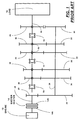
- Fig. 1 is a schematic illustration of a typical prior art 5-speed synchronized transmission.
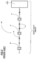
- Fig. 2 is a schematic illustration of the inertia-creating structures associated with the clutch member carrying the (output) shaft of the transmission of Fig. 1.
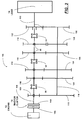
- Fig. 3 is a schematic illustration of a 5-speed synchronized transmission according to the present invention.
- Fig. 4 is a schematic illustration of the inertia-creating structures associated with the (input shaft) clutch member carrying shaft of the transmission of Fig. 3.
- Fig. 5 is a schematic illustration of an alternate embodiment of a 5-speed synchronized transmission according to the present invention.
- Fig. 6 is a schematic illustration of a compound transmission according to the present invention.
- Figs. 1 and 2 are schematic illustrations of a typical prior art 5-forward-speed, one-reverse-speed, synchronized transmission 10.
- Transmission 10 is drivingly connected to an engine, such as a diesel engine 12, by a selectively engaged and disengaged master friction clutch 14 and is adapted to drive a load (the vehicle) 16.
- An engine such as a diesel engine 12
- a selectively engaged and disengaged master friction clutch 14 and is adapted to drive a load (the vehicle) 16.
- a load the vehicle
- Medium- and heavy-duty vehicles will typically have a gross combined weight (GCW) of between 10,000 and 80,000 pounds.
- GGW gross combined weight
- Transmissions of this general type will have 4-7 forward speeds and are manually shifted by means of synchronized jaw clutches. Examples of such transmissions and synchronizers may be seen by reference to U.S. Pats. No. 4,788,889; 5,497,867; 4,462,489 and 3,221,851.
- Engine 12 will drive the input elements 14A of master clutch 14, which may be frictionally engaged and disengaged from the clutch output elements 14B splined to input shaft 18.
- Input shaft 18 carries an input gear 20 rotationally fixed thereto, which meshes with a countershaft gear 22 fixed to countershaft 24.
- Countershaft 24 also carries countershaft gears 26, 28, 30, 32 and 34 fixed thereto.
- Drive gears 36, 38, 40, 42 and 44 are rotationally supported on an output shaft 46 drivingly connected to the load by means of needle or roller bearings 48.
- Drive gears 36, 38, 40 and 42 are meshed with countershaft gears 26, 28, 30 and 32, respectively, while reverse drive gear 44 is meshed with a reverse idler (not shown), which is meshed with countershaft gear 34.
- Double-sided, synchronized jaw clutch members 50, 52 and 54 are carried by the output shaft 46 for selectively clutching the drive gears, one at a time, to the output shaft 46.
- the synchronized clutch members are axially positioned by shift forks (not shown) associated with a shift bar housing assembly (not shown) or the like.
- Clutch 54 may clutch either gear 44 or 42 to the output shaft to engage reverse or first gear, respectively.
- Clutch 52 may clutch either gear 40 or 38 to the output shaft to engage second or third gear, respectively.
- Clutch 50 may clutch either gear 36 or 20 to the output shaft to engage fourth or fifth speed, respectively.
- Fig. 2 schematically illustrates the rotating inertia associated with the output shaft assembly 46A of a prior art synchronized transmission. This is the inertia that must be overcome by the synchronizers of the synchronized jaw clutches 50, 52 or 54 to cause the engaging jaw clutch member to rotate at a synchronous speed with the gear being engaged. As may be seen, in addition to the inertia of the shaft 46, the clutches 50, 52 and 54, and the bearing 48, the synchronizers of the clutches are also subject to the relatively massive inertia of the load 16.
- Figs. 3 and 4 illustrate a preferred embodiment of a 5-speed synchronized transmission 100 utilizing the improved structure of the present invention. Elements of the transmission 100 illustrated in Figs. 3 and 4 which are structurally and functionally identical or substantially identical to elements of transmission 10 are assigned like reference numerals.
- Five-forward-speed, one-reverse-speed transmission 100 is drivingly connected to engine 12 by means of selectively engaged and disengaged master friction clutch 14 and includes an output shaft 102 drivingly connected to the vehicle load 16.
- Transmission 100 includes a relatively elongated input shaft 104, which is splined to the output elements 14B of the master clutch and which also carries the synchronized jaw clutch members 50, 52 and 54 for rotation therewith, as well as supporting input drive gears 106, 108, 110, 112 and 114 for rotation relative thereto on needle or ball bearings 48.
- a countershaft 11 6 is generally parallel to an axially offset the input shaft 104 and output shaft 102 and carries countershaft gears 118, 120, 124, 126, 128 and 130 fixed for rotation therewith.
- Countershaft gears 118, 120, 124 and 126 are constantly meshed with input drive gears 106, 108, 110 and 112, respectively.
- Countershaft gear 128 is constantly meshed with a reverse idler gear (not shown), which in turn is meshed with the reverse input drive gear 114.
- Countershaft gear 130 is constantly meshed with an output gear 132 fixed for rotation on output shaft 102.
- Clutch 54 may clutch either gear 132 or 114 to the input shaft 104 for fifth speed or reverse operation, respectively.
- Clutch 52 may clutch either gear 112 or 110 to the input shaft 104 for first gear or second gear, respectively.
- Clutch 50 may clutch either gear 108 or 106 to the input shaft 104 for third gear or fourth gear operation, respectively.
- Fig. 4 schematically illustrates the rotating inertia associated with the input shaft assembly 104A of the synchronized transmission 100 of the present invention. This is the inertia that must be overcome by the synchronizers of the synchronized jaw clutches 50, 52 or 54 to cause the engaging jaw clutch member to rotate at a synchronous speed with the gear being engaged. As may be seen, in addition to the inertia of the input shaft 104, the clutches 50, 52 and 54, and the bearings 48, the synchronizers are also subject to the rotating inertia of the driven clutch disk 14B.
- the rotating inertia of the driven master clutch members 14B is relatively minute compared to the rotating inertia of the load 16. Accordingly, it may be seen that by utilizing the structure of the present invention, the rotating inertia required to be overcome by the synchronized clutches is considerably reduced, thus providing an easier transmission to shift.
- Fig. 5 illustrates an alternate embodiment of a 5-speed transmission 200 utilizing the improved structure of the present invention.
- Transmission 200 differs from transmission 100 principally in that an extra set of gearing is utilized, which allows the transmission to maintain a standard progressive H-type shift pattern without the use of a specially configured shift bar housing assembly.
- the driven members 14B of the master friction clutch 14 are splined to an elongated input shaft 204.
- the input shaft 204 supports input drive gears 20, 36, 38, 40, 42 and 44, which, with the exception of gear 44, which meshes with a reverse idler (not shown), are constantly meshed with countershaft gears 22, 26, 28, 30, 32 and 34, respectively, fixed to a countershaft 206, which is substantially parallel to but offset the input shaft 204 and output shaft 208.
- the output shaft 208 which is drivingly connected to the load 15.
- Countershaft 206 also carries a countershaft gear 210, which meshes with an output gear 212 fixed to the output shaft 208.
- transmission 200 By utilizing an additional gear layer (gears 44 and 34) as compared to transmission 100, transmission 200 retains a progressive engagement pattern, allowing a standard H-type shift pattern and the use of an unmodified shift bar housing assembly.
- Clutch member 54 may be utilized to clutch either gear 44 or 42 to the input shaft 204 for reverse or first gear operation.
- Clutch 52 may be utilized to clutch either gear 40 or 38 to the input shaft 204 for second or third gear operation, respectively.
- Clutch 50 may be utilized to clutch either gear 36 or 20 to the input shaft 24 for fourth gear or fifth gear operation, respectively.
- the input shaft drive gears are all supported on the input shaft by means of ball or needle bearings 48, as was the case with transmissions 10 and 100 described above.
- Fig. 6 schematically illustrates a compound, twin countershaft transmission providing up to 20 forward drive ratios and utilizing the transmission structure of the present invention.
- Transmission 300 includes a manually shifted, synchronized main transmission section 302 and a combined splitter-and-range-type auxiliary section 304.
- Compound transmissions of this type are known in the prior art and may be seen in greater detail by reference to U.S. Pats. No. 4,754,665; 5,390,561 and 5,546,823, the disclosures of which are incorporated herein by reference.
- the combined splitter-and-range-type auxiliary section 304 utilized in transmission 300 is substantially functionally and structurally identical to the auxiliary sections described in detail in aforementioned U.S. Pats. No.
- the elongated input shaft 306 carries all of the synchronized jaw clutch members 50, 52 and 54, as was the case in transmissions 100 and 200 described above.
- An extra layer of gearing, countershaft gears 308 and main section output gear 310, are provided, with gear 310 being fixed to the shaft 312, defining the output shaft of the main transmission section and the input shaft of the auxiliary transmission section.
- the main section jaw clutch synchronizers are exposed to a relatively low inertia, which does not include the inertia of the auxiliary transmission section 304 or the inertia of the load (not shown).
- a new and improved transmission structure is provided for manually shifted, synchronized transmissions which, when the transmission is in neutral and the master clutch is fully disengaged, will considerably reduce the inertia to which the synchronizers are subjected during engagement of a target gear ratio.
Landscapes
- Engineering & Computer Science (AREA)
- General Engineering & Computer Science (AREA)
- Mechanical Engineering (AREA)
- Structure Of Transmissions (AREA)
- Gear Transmission (AREA)
- Transmission Devices (AREA)
Applications Claiming Priority (2)
| Application Number | Priority Date | Filing Date | Title |
|---|---|---|---|
| GB0001996A GB2358680A (en) | 2000-01-31 | 2000-01-31 | A transmission with low inertia shaft |
| GB0001996 | 2000-01-31 |
Publications (2)
| Publication Number | Publication Date |
|---|---|
| EP1122463A2 true EP1122463A2 (fr) | 2001-08-08 |
| EP1122463A3 EP1122463A3 (fr) | 2006-08-16 |
Family
ID=9884538
Family Applications (1)
| Application Number | Title | Priority Date | Filing Date |
|---|---|---|---|
| EP01102004A Withdrawn EP1122463A3 (fr) | 2000-01-31 | 2001-01-30 | Arbre embrayable à faible inertie pour transmissions |
Country Status (5)
| Country | Link |
|---|---|
| US (1) | US20010017061A1 (fr) |
| EP (1) | EP1122463A3 (fr) |
| CN (1) | CN1316348A (fr) |
| BR (1) | BR0100407B1 (fr) |
| GB (1) | GB2358680A (fr) |
Cited By (3)
| Publication number | Priority date | Publication date | Assignee | Title |
|---|---|---|---|---|
| US6718841B1 (en) | 1999-12-02 | 2004-04-13 | Zf Friedrichshafen Ag | Gearbox |
| WO2017121664A1 (fr) * | 2016-01-13 | 2017-07-20 | GETRAG B.V. & Co. KG | Boîte de vitesses de véhicule automobile devant être montée longitudinalement dans un véhicule automobile |
| EP3536610A1 (fr) * | 2018-03-07 | 2019-09-11 | Bell Helicopter Textron Inc. | Ensembles de couplage de trajet de couple pour avion à rotors basculants |
Families Citing this family (6)
| Publication number | Priority date | Publication date | Assignee | Title |
|---|---|---|---|---|
| GB2424682A (en) * | 2005-04-01 | 2006-10-04 | John Gordon Madge | Plural power path gearbox. |
| EP1921349B1 (fr) * | 2006-11-09 | 2012-10-17 | Magneti Marelli S.p.A. | Procédé pour commander un système de propulsion assistée dans un véhicule automobile |
| US7866598B2 (en) * | 2008-03-06 | 2011-01-11 | Karem Aircraft, Inc. | Rotorcraft engine and rotor speed synchronization |
| DE102008064514A1 (de) * | 2008-12-22 | 2010-07-01 | Fineschnitt Gmbh | Getriebeeinheit |
| CN108036042B (zh) * | 2017-11-07 | 2020-02-14 | 北京理工大学 | 一种带有磁流变换挡装置的变速箱及使用方法 |
| US10759527B2 (en) | 2018-03-07 | 2020-09-01 | Textron Innovations Inc. | Torque path coupling assemblies for tiltrotor aircraft |
Citations (13)
| Publication number | Priority date | Publication date | Assignee | Title |
|---|---|---|---|---|
| US3221851A (en) | 1963-10-16 | 1965-12-07 | Eaton Mfg Co | Synchronized positive clutches |
| US4152949A (en) | 1977-04-18 | 1979-05-08 | Eaton Corporation | Extended range transmission |
| US4271724A (en) | 1978-12-26 | 1981-06-09 | Eaton Corporation | Synchronized transmission with torque converter by-pass |
| US4462489A (en) | 1981-07-31 | 1984-07-31 | Eaton Corporation | Synchronizer spring pin |
| US4567785A (en) | 1983-12-16 | 1986-02-04 | Eaton Corporation | Directly mounted master shift control |
| US4722237A (en) | 1986-12-12 | 1988-02-02 | Eaton Corporation | Fluid actuated shift bar housing assembly having a centering cylinder therein |
| US4754663A (en) | 1985-09-10 | 1988-07-05 | Kabushiki Kaisha Sankyo Seiki Seisakusho | Articulation structure of rotatable arm |
| US4754665A (en) | 1986-02-05 | 1988-07-05 | Eaton Corporation | Auxiliary transmission section |
| US4788889A (en) | 1987-03-19 | 1988-12-06 | Eaton Corporation | Mechanical transmission and control method therefor |
| US5370013A (en) | 1993-05-20 | 1994-12-06 | Eaton Corporation | Helically geared compound transmission |
| US5390561A (en) | 1993-05-20 | 1995-02-21 | Eaton Corporation | Compound transmission |
| US5497867A (en) | 1993-12-27 | 1996-03-12 | Eaton Corporation | Synchronizer with cone cup locater pins |
| US5546823A (en) | 1993-05-20 | 1996-08-20 | Eaton Corporation | High-capacity compound transmission |
Family Cites Families (3)
| Publication number | Priority date | Publication date | Assignee | Title |
|---|---|---|---|---|
| US5335562A (en) * | 1992-12-08 | 1994-08-09 | Mastroianni Cesare G | Multi-speed rear wheel drive transmission with reduced in-neutral gear rattle |
| US5416698A (en) * | 1993-07-09 | 1995-05-16 | Eaton Corporation | Input shaft overspeed warning system |
| DE19614930C1 (de) * | 1996-04-16 | 1997-08-21 | Ford Werke Ag | Wechselgetriebe-Konzept für Kraftfahrzeuge |
-
2000
- 2000-01-31 GB GB0001996A patent/GB2358680A/en not_active Withdrawn
-
2001
- 2001-01-29 US US09/772,270 patent/US20010017061A1/en not_active Abandoned
- 2001-01-30 EP EP01102004A patent/EP1122463A3/fr not_active Withdrawn
- 2001-01-31 BR BRPI0100407-7A patent/BR0100407B1/pt not_active IP Right Cessation
- 2001-01-31 CN CN01103329A patent/CN1316348A/zh active Pending
Patent Citations (13)
| Publication number | Priority date | Publication date | Assignee | Title |
|---|---|---|---|---|
| US3221851A (en) | 1963-10-16 | 1965-12-07 | Eaton Mfg Co | Synchronized positive clutches |
| US4152949A (en) | 1977-04-18 | 1979-05-08 | Eaton Corporation | Extended range transmission |
| US4271724A (en) | 1978-12-26 | 1981-06-09 | Eaton Corporation | Synchronized transmission with torque converter by-pass |
| US4462489A (en) | 1981-07-31 | 1984-07-31 | Eaton Corporation | Synchronizer spring pin |
| US4567785A (en) | 1983-12-16 | 1986-02-04 | Eaton Corporation | Directly mounted master shift control |
| US4754663A (en) | 1985-09-10 | 1988-07-05 | Kabushiki Kaisha Sankyo Seiki Seisakusho | Articulation structure of rotatable arm |
| US4754665A (en) | 1986-02-05 | 1988-07-05 | Eaton Corporation | Auxiliary transmission section |
| US4722237A (en) | 1986-12-12 | 1988-02-02 | Eaton Corporation | Fluid actuated shift bar housing assembly having a centering cylinder therein |
| US4788889A (en) | 1987-03-19 | 1988-12-06 | Eaton Corporation | Mechanical transmission and control method therefor |
| US5370013A (en) | 1993-05-20 | 1994-12-06 | Eaton Corporation | Helically geared compound transmission |
| US5390561A (en) | 1993-05-20 | 1995-02-21 | Eaton Corporation | Compound transmission |
| US5546823A (en) | 1993-05-20 | 1996-08-20 | Eaton Corporation | High-capacity compound transmission |
| US5497867A (en) | 1993-12-27 | 1996-03-12 | Eaton Corporation | Synchronizer with cone cup locater pins |
Cited By (3)
| Publication number | Priority date | Publication date | Assignee | Title |
|---|---|---|---|---|
| US6718841B1 (en) | 1999-12-02 | 2004-04-13 | Zf Friedrichshafen Ag | Gearbox |
| WO2017121664A1 (fr) * | 2016-01-13 | 2017-07-20 | GETRAG B.V. & Co. KG | Boîte de vitesses de véhicule automobile devant être montée longitudinalement dans un véhicule automobile |
| EP3536610A1 (fr) * | 2018-03-07 | 2019-09-11 | Bell Helicopter Textron Inc. | Ensembles de couplage de trajet de couple pour avion à rotors basculants |
Also Published As
| Publication number | Publication date |
|---|---|
| GB0001996D0 (en) | 2000-03-22 |
| GB2358680A (en) | 2001-08-01 |
| CN1316348A (zh) | 2001-10-10 |
| EP1122463A3 (fr) | 2006-08-16 |
| BR0100407A (pt) | 2001-09-11 |
| US20010017061A1 (en) | 2001-08-30 |
| BR0100407B1 (pt) | 2009-01-13 |
Similar Documents
| Publication | Publication Date | Title |
|---|---|---|
| US11231090B2 (en) | Heavy duty transmission architecture | |
| JP3533580B2 (ja) | 複式変速機 | |
| US5447478A (en) | Auxiliary transmission section | |
| US5370013A (en) | Helically geared compound transmission | |
| JP2762274B2 (ja) | 機械式変速機およびその制御方法 | |
| JP2941277B2 (ja) | 自動車ギアボックス | |
| EP0233480B1 (fr) | Section auxiliaire de transmission | |
| EP0714802B1 (fr) | Transmission composée à haute capacité | |
| US5679096A (en) | Torque control for powertrain and change-gear transmission utilized in same | |
| JP3082043B2 (ja) | 二段変速歯車列組立体 | |
| EP2126411B2 (fr) | Transmission de vehicule a double embrayage a rapports multiples | |
| EP0004045A1 (fr) | Transmission à changement de vitesse | |
| US5511437A (en) | Compound vehicular transmission | |
| US5881600A (en) | Transmission for motor vehicles | |
| EP1122463A2 (fr) | Arbre embrayable à faible inertie pour transmissions | |
| EP0040864B1 (fr) | Transmission à changement de puissance | |
| JPH0874883A (ja) | スプリッタ形補助変速部用のブロッキング機構 | |
| US5394763A (en) | Auxiliary transmission section | |
| US5934142A (en) | Two piece continuous mesh synchronized reverse idler system | |
| CA2126612C (fr) | Boite de vitesse auxiliaire | |
| JP3044467B2 (ja) | 多段変速機 | |
| CA2126766A1 (fr) | Prise de mouvement d'arbre de sortie transmission |
Legal Events
| Date | Code | Title | Description |
|---|---|---|---|
| PUAI | Public reference made under article 153(3) epc to a published international application that has entered the european phase |
Free format text: ORIGINAL CODE: 0009012 |
|
| AK | Designated contracting states |
Kind code of ref document: A2 Designated state(s): AT BE CH CY DE DK ES FI FR GB GR IE IT LI LU MC NL PT SE TR |
|
| AX | Request for extension of the european patent |
Free format text: AL;LT;LV;MK;RO;SI |
|
| PUAL | Search report despatched |
Free format text: ORIGINAL CODE: 0009013 |
|
| AK | Designated contracting states |
Kind code of ref document: A3 Designated state(s): AT BE CH CY DE DK ES FI FR GB GR IE IT LI LU MC NL PT SE TR |
|
| AX | Request for extension of the european patent |
Extension state: AL LT LV MK RO SI |
|
| AKX | Designation fees paid | ||
| STAA | Information on the status of an ep patent application or granted ep patent |
Free format text: STATUS: THE APPLICATION IS DEEMED TO BE WITHDRAWN |
|
| 18D | Application deemed to be withdrawn |
Effective date: 20070217 |
|
| REG | Reference to a national code |
Ref country code: DE Ref legal event code: 8566 |