EP1122483A2 - Raccord de tuyaux - Google Patents
Raccord de tuyaux Download PDFInfo
- Publication number
- EP1122483A2 EP1122483A2 EP01200364A EP01200364A EP1122483A2 EP 1122483 A2 EP1122483 A2 EP 1122483A2 EP 01200364 A EP01200364 A EP 01200364A EP 01200364 A EP01200364 A EP 01200364A EP 1122483 A2 EP1122483 A2 EP 1122483A2
- Authority
- EP
- European Patent Office
- Prior art keywords
- coupling
- sections
- disc
- connecting part
- section
- Prior art date
- Legal status (The legal status is an assumption and is not a legal conclusion. Google has not performed a legal analysis and makes no representation as to the accuracy of the status listed.)
- Granted
Links
- 230000008878 coupling Effects 0.000 title claims abstract description 155
- 238000010168 coupling process Methods 0.000 title claims abstract description 155
- 238000005859 coupling reaction Methods 0.000 title claims abstract description 155
- 230000000284 resting effect Effects 0.000 claims abstract description 4
- 238000010438 heat treatment Methods 0.000 claims description 5
- 230000013011 mating Effects 0.000 claims description 5
- 229910010293 ceramic material Inorganic materials 0.000 claims description 2
- 238000010276 construction Methods 0.000 description 2
- 238000001816 cooling Methods 0.000 description 1
- 230000001419 dependent effect Effects 0.000 description 1
- 239000000463 material Substances 0.000 description 1
- 230000000717 retained effect Effects 0.000 description 1
- 238000007789 sealing Methods 0.000 description 1
Images

Classifications
-
- F—MECHANICAL ENGINEERING; LIGHTING; HEATING; WEAPONS; BLASTING
- F16—ENGINEERING ELEMENTS AND UNITS; GENERAL MEASURES FOR PRODUCING AND MAINTAINING EFFECTIVE FUNCTIONING OF MACHINES OR INSTALLATIONS; THERMAL INSULATION IN GENERAL
- F16L—PIPES; JOINTS OR FITTINGS FOR PIPES; SUPPORTS FOR PIPES, CABLES OR PROTECTIVE TUBING; MEANS FOR THERMAL INSULATION IN GENERAL
- F16L37/00—Couplings of the quick-acting type
- F16L37/56—Couplings of the quick-acting type for double-walled or multi-channel pipes or pipe assemblies
-
- F—MECHANICAL ENGINEERING; LIGHTING; HEATING; WEAPONS; BLASTING
- F16—ENGINEERING ELEMENTS AND UNITS; GENERAL MEASURES FOR PRODUCING AND MAINTAINING EFFECTIVE FUNCTIONING OF MACHINES OR INSTALLATIONS; THERMAL INSULATION IN GENERAL
- F16L—PIPES; JOINTS OR FITTINGS FOR PIPES; SUPPORTS FOR PIPES, CABLES OR PROTECTIVE TUBING; MEANS FOR THERMAL INSULATION IN GENERAL
- F16L29/00—Joints with fluid cut-off means
- F16L29/007—Joints with cut-off devices controlled separately
-
- F—MECHANICAL ENGINEERING; LIGHTING; HEATING; WEAPONS; BLASTING
- F16—ENGINEERING ELEMENTS AND UNITS; GENERAL MEASURES FOR PRODUCING AND MAINTAINING EFFECTIVE FUNCTIONING OF MACHINES OR INSTALLATIONS; THERMAL INSULATION IN GENERAL
- F16L—PIPES; JOINTS OR FITTINGS FOR PIPES; SUPPORTS FOR PIPES, CABLES OR PROTECTIVE TUBING; MEANS FOR THERMAL INSULATION IN GENERAL
- F16L37/00—Couplings of the quick-acting type
- F16L37/28—Couplings of the quick-acting type with fluid cut-off means
- F16L37/30—Couplings of the quick-acting type with fluid cut-off means with fluid cut-off means in each of two pipe-end fittings
- F16L37/367—Couplings of the quick-acting type with fluid cut-off means with fluid cut-off means in each of two pipe-end fittings with two gate valves or sliding valves
Definitions
- the invention relates to a coupling for coupling together pipe sections, comprising a first coupling section and a second coupling section that can be coupled to the first coupling section and can be locked relative to the first coupling section in the direction of coupling, the two coupling sections each being provided with a first duct and a second duct running parallel thereto, and also comprising a male connecting part having therein a duct that connects to the first duct, and a female connecting part that connects to the second duct, it being possible for the male connecting part of the one coupling section to be accommodated in a mating manner in the female connecting part of the other coupling section, in such a way that in the coupled state of the two coupling sections the first and second ducts in the two coupling sections can form continuous ducts, and a spring-loaded non-return valve being accommodated in the male connecting part of each coupling section, which non-return valve acts towards the free end of the male connecting part.
- the known coupling is used in systems in which two pipes are being used to convey a thermal medium, in other words for heating or cooling.
- a first pipe runs to, for example, a heat exchanger, and the second pipe runs away from the heat exchanger.
- a non-return valve is also accommodated in each of the second ducts connecting to the female connecting parts.
- the ducts in the male connecting parts and the second ducts connecting to the female connecting parts are shut off towards the outside by a non-return valve.
- the non-return valves are opened automatically, so that continuous ducts are produced in the coupling.
- the known coupling has the disadvantage that in the uncoupled state of the two coupling sections the ducts in the coupling sections are shut off only towards the outside by the non--return valves.
- the non-return valves can easily be opened from the outside, with the result that it is possible for medium present in the ducts to leak out. This can be a particular disadvantage if said medium is under pressure.
- the object of the invention is to provide a coupling of the abovementioned type by means of which this disadvantage can be overcome.
- each of the two coupling sections is provided with a shut-off element for shutting off the ducts in the coupling section in question, which shut-off element is composed of two discs resting against each other, a first disc which is provided with two bores situated diametrically opposite each other, which bores are always in line with the two ducts in the coupling section, and a second disc which is likewise provided with two bores situated diametrically opposite each other, in the uncoupled state of the two coupling sections the bores in the one disc being covered by the other disc, and in the coupled state of the two coupling sections the two discs being rotatable relative to each other, so that the bores in the one disc can be placed opposite the bores in the other disc.
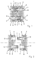
- the coupling shown very diagrammatically in Figs. 1 and 2 comprises a first coupling section 1 and a second coupling section 2 that can be coupled to the first coupling section 1.
- the two coupling sections in Figs. 1 and 2 are essentially identical in design.
- Each coupling section 1, 2 is provided with a first duct 3 and a second duct 4 running parallel thereto.
- Each coupling section 1, 2 is further provided with a male connecting part 5 and a female connecting part 6, it being possible for the male connecting part 5 of the one coupling section to be accommodated in a mating manner in the female connecting part 6 of the other coupling section, as shown in Fig. 1.
- Sealing rings such as O-rings provide for the required seal here.
- the non-return valve 7 is designed to be opened by a medium flowing through the connecting part in question.
- the direction of flow of a medium in the two ducts is indicated by arrows in Fig. 1.
- the non-return valves 7 are closed (see Fig. 2).
- the male connecting part 5 and the female connecting part 6 of each coupling section 1, 2 form an integral part of an end plate 8 on the connection side of the coupling section 1, 2 in question.
- Each of the two coupling sections 1, 2 is provided with a shut-off element 9, 10 for shutting off the ducts 3, 4 in the coupling section 1, 2.
- the shut-off element 9, 10 consists of two discs resting against each other, a first disc 9 and a second disc 10.
- the first disc 9 is provided with two bores 11, situated diametrically opposite each other and in line with the two ducts 3, 4 in the coupling section.
- the second disc 10 is likewise provided with two bores 12, situated diametrically opposite each other. In the uncoupled state of the two coupling sections 1, 2 the bores in the one disc are covered by the other disc (see Fig. 2).
- the two discs 9, 10 are rotatable relative to each other, so that the bores in the one disc can be placed opposite the bores in the other disc (see Fig. 1).
- the bores are situated opposite each other, so that two continuous ducts are present in the coupling.
- the discs 9 and 10 are preferably made of a ceramic material, but other materials suitable for these types of discs can also be used.
- the second disc 10 is situated at the side of the first disc 9 facing the connection side of the coupling section in question.
- the coupling In the coupled state of the two coupling sections 1, 2 (see Fig. 1) the free end part of the male connecting part of the one coupling section projects into one of the bores 12 of the second disc 10 of the other coupling section.
- the head end face of the male connecting part 5 coincides substantially with the contact face of the two discs 9 and 10 of the other coupling section.
- the construction of the coupling is further such that in the coupled state of the two coupling sections 1, 2 the two end plates 8 having thereon the mating male and female connecting parts 5 and 6 and the second discs 10 of the two coupling sections 1 and 2 are rotatable together relative to the first discs 9 that are immovably connected to the coupling sections 1 and 2.
- the coupling shown in Figs. 1 and 2 is completely or virtually completely leak-free, even if the medium in the ducts 3 and 4 remains under pressure during the uncoupling of the coupling.
- the end plates 8 with the connecting parts 5 and 6, and the second discs 10 connected to the end plates 8 are first rotated from the position shown in Fig. 1 through, for example, 90° relative to the first discs 9, to the position shown in Fig. 2.
- the ducts 3 and 4 in the two coupling sections 1 and 2 are shut off.
- the discs rotate relative to each other the head end face of the male connecting part 5 of each coupling section will slide over the first disc 9 of the other coupling section.
- FIG. 3 A practical embodiment of the coupling of Figs. 1 and 2 in the coupled state is shown diagrammatically in Fig. 3.
- Fig. 3 corresponding parts are indicated by the same reference numerals as those in Figs. 1 and 2.
- the various parts may differ slightly in shape.
- the function and operation is, however, the same as in the case of the coupling shown in Figs. 1 and 2, so that the description appertaining to Figs. 1 and 2 is fully applicable to Fig. 3.
- the first coupling section 1 is accommodated in a first housing 21, and the second coupling section 2 is accommodated in a second housing 22.
- the first housing 21 is provided with ducts 23 and 24 that connect to the ducts 3 and 4 in the first coupling section 1.
- the second housing 22 is provided with ducts 25 and 26 that connect to the ducts 3 and 4 in the second coupling section 2.
- the second housing 22 is provided with a cylindrical part 27.
- a connecting part 28 with a cylindrical bore 29 is fitted around this cylindrical part 27.
- the connecting part 28 is rotatable about the cylindrical part 27 and provides a seal thereon.
- the connecting part 28 is provided with two circular ducts 30 and 31 that are open towards the bore 29 and connect to the ducts 25 and 26 in the second housing 22.
- Ducts 32 and 33 connect to these circular ducts 30 and 31.
- the connecting part 28 is retained on the cylindrical part 27 by, for example, a locking ring 34.
- first locking means that are designed to ensure that in the coupled state of the two coupling sections 1 and 2, when the two discs 10 are rotated relative to their position in the uncoupled state of the coupling sections 1 and 2, the two coupling sections 1 and 2 cannot be uncoupled.
- the first locking means consist of a sort of bayonet closure and comprise a number of radial projections 41 of the end plate 8 of the second coupling section 2 and a circular opening 42 in the first housing 21, which opening is bounded in the axial direction by a radially inward projecting edge 43 that is provided with openings (not shown), through which the projections 41 can move when the coupling sections 1 and 2 are inserted into each other.
- the projections 41 grip behind the edge 43, with the result that the two coupling sections 1 and 2 can no longer move apart.
- the connecting parts 5 and 6 that have been inserted into each other and the second discs 10 can be rotated by means of a rotary knob 44 provided with a shaft 45, which near its end 46 is coupled in the direction of rotation to the end plate 8 of the second coupling section 2.
- Each of the two coupling sections 1, 2 of the embodiment of the coupling according to the invention shown in Fig. 3 is further provided with second locking means that are designed to ensure that in the uncoupled state of the two coupling sections 1 and 2 the second disc 10 is not rotatable relative to the first disc 9.
- the second locking means in each of the two coupling sections 1, 2 comprise a ring 51, which is provided with radial projections 52 on the outside and radial projections 53 on the inside.
- the ring 51 is movable in the axial direction in the housing 21 or 22, the projections 52 being slidable in longitudinal grooves 54 on the inside of the housing. Owing to the fact that the projections 52 are accommodated in the longitudinal grooves 54, the ring 51 is not rotatable relative to the housing.
- a spring 55 presses the ring 51 in the direction of the connection side of the coupling section 1 or 2.
- the projections 53 fall into a circular groove 56 in the end plate 8, so that the end plate 8 is rotatable relative to the ring 51, and thus relative to the housing.
- the uncoupled state of the two coupling sections 1, 2, in which the end plate 8 has rotated into a certain position (otherwise the two coupling sections 1, 2 cannot be coupled and uncoupled) the projections 53 fall into radial openings (not shown) situated opposite the projections 53 in the end plate 8.
- the spring 55 presses the ring 51 with the projections 53 into the position concerned.
- the end plate 8 therefore cannot be rotated relative to the housing 21 or 22, and the second disc 10 cannot be rotated relative to the first disc 9, so that the shut-off element 9, 10 keeps the ducts 3 and 4 shut off.
- the coupling according to the invention is suitable in particular for use in central heating systems.
- Lines (hoses) that are connected at the other end to a radiator or the like can be connected to the ducts 31 and 32.
- Fixed pipes of the central heating system can be connected to the ducts 23 and 24.
- the two housings 21 and 22 with the coupling sections 1 and 2 form, as it were, a socket and plug.
- a second coupling section 2 integral with a radiator or the like and to couple the second coupling section 2 to a first coupling section 1 in a fixed position (for example, fixed on a wall), so that the radiator or the like can be connected directly to a central heating system.
Landscapes
- Engineering & Computer Science (AREA)
- General Engineering & Computer Science (AREA)
- Mechanical Engineering (AREA)
- Quick-Acting Or Multi-Walled Pipe Joints (AREA)
Applications Claiming Priority (2)
| Application Number | Priority Date | Filing Date | Title |
|---|---|---|---|
| NL1014275A NL1014275C1 (nl) | 2000-02-03 | 2000-02-03 | Koppeling voor het met elkaar koppelen van leidingdelen. |
| NL1014275 | 2000-02-03 |
Publications (3)
| Publication Number | Publication Date |
|---|---|
| EP1122483A2 true EP1122483A2 (fr) | 2001-08-08 |
| EP1122483A3 EP1122483A3 (fr) | 2002-04-17 |
| EP1122483B1 EP1122483B1 (fr) | 2004-07-21 |
Family
ID=19770738
Family Applications (1)
| Application Number | Title | Priority Date | Filing Date |
|---|---|---|---|
| EP20010200364 Expired - Lifetime EP1122483B1 (fr) | 2000-02-03 | 2001-02-01 | Raccord de tuyaux |
Country Status (3)
| Country | Link |
|---|---|
| EP (1) | EP1122483B1 (fr) |
| DE (1) | DE60104339T2 (fr) |
| NL (1) | NL1014275C1 (fr) |
Cited By (2)
| Publication number | Priority date | Publication date | Assignee | Title |
|---|---|---|---|---|
| GB2466037A (en) * | 2008-12-09 | 2010-06-16 | Bifold Fluidpower Ltd | Hydraulic coupling with seals on both male and female members |
| DE102017220550A1 (de) * | 2017-11-17 | 2019-05-23 | Zf Friedrichshafen Ag | Kühlsystem für ein Antriebssystem und Fahrzeugantriebssystem |
Citations (1)
| Publication number | Priority date | Publication date | Assignee | Title |
|---|---|---|---|---|
| EP0382484A2 (fr) | 1989-02-08 | 1990-08-16 | Hollister Incorporated | Raccord hermaphrodite pour système thermique anatomique |
Family Cites Families (4)
| Publication number | Priority date | Publication date | Assignee | Title |
|---|---|---|---|---|
| US2399525A (en) * | 1943-12-04 | 1946-04-30 | Thompson Prod Inc | Quick disconnect coupling |
| FR2479397A1 (fr) * | 1980-03-31 | 1981-10-02 | Ferodo Sa | Robinet, notamment pour le reglage du chauffage de l'habitacle d'un vehicule automobile |
| DE3436079A1 (de) * | 1984-10-02 | 1986-04-10 | Leybold-Heraeus GmbH, 5000 Köln | Oelgedichtete vakuumpumpe |
| DE3680177D1 (de) * | 1985-11-06 | 1991-08-14 | Voss Armaturen | Schaltventil mit keramischen ventilelementen. |
-
2000
- 2000-02-03 NL NL1014275A patent/NL1014275C1/nl not_active IP Right Cessation
-
2001
- 2001-02-01 DE DE2001604339 patent/DE60104339T2/de not_active Expired - Lifetime
- 2001-02-01 EP EP20010200364 patent/EP1122483B1/fr not_active Expired - Lifetime
Patent Citations (1)
| Publication number | Priority date | Publication date | Assignee | Title |
|---|---|---|---|---|
| EP0382484A2 (fr) | 1989-02-08 | 1990-08-16 | Hollister Incorporated | Raccord hermaphrodite pour système thermique anatomique |
Cited By (3)
| Publication number | Priority date | Publication date | Assignee | Title |
|---|---|---|---|---|
| GB2466037A (en) * | 2008-12-09 | 2010-06-16 | Bifold Fluidpower Ltd | Hydraulic coupling with seals on both male and female members |
| GB2466037B (en) * | 2008-12-09 | 2012-11-14 | Bifold Fluidpower Ltd | Hydraulic coupling |
| DE102017220550A1 (de) * | 2017-11-17 | 2019-05-23 | Zf Friedrichshafen Ag | Kühlsystem für ein Antriebssystem und Fahrzeugantriebssystem |
Also Published As
| Publication number | Publication date |
|---|---|
| EP1122483B1 (fr) | 2004-07-21 |
| DE60104339T2 (de) | 2004-12-02 |
| NL1014275C1 (nl) | 2001-08-06 |
| DE60104339D1 (de) | 2004-08-26 |
| EP1122483A3 (fr) | 2002-04-17 |
Similar Documents
| Publication | Publication Date | Title |
|---|---|---|
| CA2379222C (fr) | Accouplement limiteur universel | |
| US5464042A (en) | Quick connect air-conditioning coupling | |
| US3236251A (en) | Valve unit | |
| JP3354574B2 (ja) | 迅速連結式継手 | |
| EP0897080B1 (fr) | Raccord de tuyaux pour un appareil sous pression | |
| US3472270A (en) | Ball valves | |
| GB2234566A (en) | Double-pipe pipe coupling | |
| US6213149B1 (en) | In-line diversion valve with flow-through capability | |
| US20050230969A1 (en) | Floating seal for undersea hydraulic coupling | |
| CN101142433A (zh) | 用于流体的歧管 | |
| US3377087A (en) | Union for connecting conduits | |
| JPH06154520A (ja) | ろ過器組立体及びろ過方法 | |
| JP7234355B2 (ja) | 流体継手 | |
| RU2008102977A (ru) | Гидравлическая муфта | |
| ATE178699T1 (de) | Schnellrohrkupplung mit einem sicherheitsventil | |
| AU2019100255A4 (en) | Quick Coupler Assembly | |
| EP1122483B1 (fr) | Raccord de tuyaux | |
| US6712027B2 (en) | Hot water heating system and connector for use therewith | |
| EP0890053B1 (fr) | Couplage rapide pour tuyaux et canalisations destines a des milieux sous pression | |
| KR20090056148A (ko) | 퀵 커넥터 | |
| US4029125A (en) | Snap-fitting pipe connecting device | |
| JP2685649B2 (ja) | 流体継手 | |
| CN207599215U (zh) | 一种用于管的快装接头 | |
| CA1281049C (fr) | Raccord de tuyauterie | |
| US2675250A (en) | Quick-disconnect valved coupling |
Legal Events
| Date | Code | Title | Description |
|---|---|---|---|
| PUAI | Public reference made under article 153(3) epc to a published international application that has entered the european phase |
Free format text: ORIGINAL CODE: 0009012 |
|
| AK | Designated contracting states |
Kind code of ref document: A2 Designated state(s): AT BE CH CY DE DK ES FI FR GB GR IE IT LI LU MC NL PT SE TR Kind code of ref document: A2 Designated state(s): DE FR GB NL |
|
| AX | Request for extension of the european patent |
Free format text: AL;LT;LV;MK;RO;SI |
|
| PUAL | Search report despatched |
Free format text: ORIGINAL CODE: 0009013 |
|
| AK | Designated contracting states |
Kind code of ref document: A3 Designated state(s): AT BE CH CY DE DK ES FI FR GB GR IE IT LI LU MC NL PT SE TR |
|
| AX | Request for extension of the european patent |
Free format text: AL;LT;LV;MK;RO;SI |
|
| 17P | Request for examination filed |
Effective date: 20020919 |
|
| AKX | Designation fees paid |
Free format text: DE FR GB NL |
|
| 17Q | First examination report despatched |
Effective date: 20030509 |
|
| GRAP | Despatch of communication of intention to grant a patent |
Free format text: ORIGINAL CODE: EPIDOSNIGR1 |
|
| GRAS | Grant fee paid |
Free format text: ORIGINAL CODE: EPIDOSNIGR3 |
|
| GRAA | (expected) grant |
Free format text: ORIGINAL CODE: 0009210 |
|
| AK | Designated contracting states |
Kind code of ref document: B1 Designated state(s): DE FR GB NL |
|
| REG | Reference to a national code |
Ref country code: GB Ref legal event code: FG4D |
|
| REG | Reference to a national code |
Ref country code: IE Ref legal event code: FG4D |
|
| REF | Corresponds to: |
Ref document number: 60104339 Country of ref document: DE Date of ref document: 20040826 Kind code of ref document: P |
|
| ET | Fr: translation filed | ||
| PLBE | No opposition filed within time limit |
Free format text: ORIGINAL CODE: 0009261 |
|
| STAA | Information on the status of an ep patent application or granted ep patent |
Free format text: STATUS: NO OPPOSITION FILED WITHIN TIME LIMIT |
|
| 26N | No opposition filed |
Effective date: 20050422 |
|
| PGFP | Annual fee paid to national office [announced via postgrant information from national office to epo] |
Ref country code: DE Payment date: 20140225 Year of fee payment: 14 Ref country code: NL Payment date: 20140227 Year of fee payment: 14 |
|
| PGFP | Annual fee paid to national office [announced via postgrant information from national office to epo] |
Ref country code: FR Payment date: 20140224 Year of fee payment: 14 |
|
| PGFP | Annual fee paid to national office [announced via postgrant information from national office to epo] |
Ref country code: GB Payment date: 20140129 Year of fee payment: 14 |
|
| REG | Reference to a national code |
Ref country code: DE Ref legal event code: R119 Ref document number: 60104339 Country of ref document: DE |
|
| REG | Reference to a national code |
Ref country code: NL Ref legal event code: V1 Effective date: 20150901 |
|
| PG25 | Lapsed in a contracting state [announced via postgrant information from national office to epo] |
Ref country code: NL Free format text: LAPSE BECAUSE OF NON-PAYMENT OF DUE FEES Effective date: 20150901 |
|
| GBPC | Gb: european patent ceased through non-payment of renewal fee |
Effective date: 20150201 |
|
| REG | Reference to a national code |
Ref country code: FR Ref legal event code: ST Effective date: 20151030 |
|
| PG25 | Lapsed in a contracting state [announced via postgrant information from national office to epo] |
Ref country code: GB Free format text: LAPSE BECAUSE OF NON-PAYMENT OF DUE FEES Effective date: 20150201 Ref country code: DE Free format text: LAPSE BECAUSE OF NON-PAYMENT OF DUE FEES Effective date: 20150901 |
|
| PG25 | Lapsed in a contracting state [announced via postgrant information from national office to epo] |
Ref country code: FR Free format text: LAPSE BECAUSE OF NON-PAYMENT OF DUE FEES Effective date: 20150302 |