EP1122487A2 - Composants avec support de transmission de lumière - Google Patents
Composants avec support de transmission de lumière Download PDFInfo
- Publication number
- EP1122487A2 EP1122487A2 EP01102149A EP01102149A EP1122487A2 EP 1122487 A2 EP1122487 A2 EP 1122487A2 EP 01102149 A EP01102149 A EP 01102149A EP 01102149 A EP01102149 A EP 01102149A EP 1122487 A2 EP1122487 A2 EP 1122487A2
- Authority
- EP
- European Patent Office
- Prior art keywords
- transmission medium
- light transmission
- light
- component
- section
- Prior art date
- Legal status (The legal status is an assumption and is not a legal conclusion. Google has not performed a legal analysis and makes no representation as to the accuracy of the status listed.)
- Withdrawn
Links
- 230000005540 biological transmission Effects 0.000 title claims description 116
- 239000012533 medium component Substances 0.000 title 1
- 230000005855 radiation Effects 0.000 claims abstract description 17
- 230000005670 electromagnetic radiation Effects 0.000 claims description 18
- 239000000463 material Substances 0.000 claims description 17
- 229910052751 metal Inorganic materials 0.000 claims description 13
- 239000002184 metal Substances 0.000 claims description 13
- 229920003023 plastic Polymers 0.000 claims description 6
- 239000004575 stone Substances 0.000 claims description 6
- 230000000694 effects Effects 0.000 claims description 5
- 239000004033 plastic Substances 0.000 claims description 5
- 239000000126 substance Substances 0.000 claims description 4
- 239000011521 glass Substances 0.000 claims description 3
- 239000002023 wood Substances 0.000 claims description 3
- 238000000149 argon plasma sintering Methods 0.000 claims description 2
- QSHDDOUJBYECFT-UHFFFAOYSA-N mercury Chemical compound [Hg] QSHDDOUJBYECFT-UHFFFAOYSA-N 0.000 abstract description 2
- 230000004913 activation Effects 0.000 abstract 2
- 238000010276 construction Methods 0.000 abstract 1
- 229910052754 neon Inorganic materials 0.000 abstract 1
- GKAOGPIIYCISHV-UHFFFAOYSA-N neon atom Chemical compound [Ne] GKAOGPIIYCISHV-UHFFFAOYSA-N 0.000 abstract 1
- 230000006870 function Effects 0.000 description 9
- 239000011505 plaster Substances 0.000 description 6
- 230000003287 optical effect Effects 0.000 description 4
- 230000008878 coupling Effects 0.000 description 3
- 238000010168 coupling process Methods 0.000 description 3
- 238000005859 coupling reaction Methods 0.000 description 3
- 230000011664 signaling Effects 0.000 description 3
- 229910000870 Weathering steel Inorganic materials 0.000 description 1
- 239000000853 adhesive Substances 0.000 description 1
- 230000001070 adhesive effect Effects 0.000 description 1
- 239000004566 building material Substances 0.000 description 1
- 239000003086 colorant Substances 0.000 description 1
- 230000001419 dependent effect Effects 0.000 description 1
- 238000005265 energy consumption Methods 0.000 description 1
- 230000007613 environmental effect Effects 0.000 description 1
- 239000002360 explosive Substances 0.000 description 1
- 229910052736 halogen Inorganic materials 0.000 description 1
- 150000002367 halogens Chemical class 0.000 description 1
- 238000010438 heat treatment Methods 0.000 description 1
- 239000011796 hollow space material Substances 0.000 description 1
- 230000001771 impaired effect Effects 0.000 description 1
- 238000001746 injection moulding Methods 0.000 description 1
- 238000002372 labelling Methods 0.000 description 1
- 230000007774 longterm Effects 0.000 description 1
- 238000004519 manufacturing process Methods 0.000 description 1
- 229910052753 mercury Inorganic materials 0.000 description 1
- 230000002093 peripheral effect Effects 0.000 description 1
- 229910052698 phosphorus Inorganic materials 0.000 description 1
- 239000011574 phosphorus Substances 0.000 description 1
- -1 phosphorus compound Chemical class 0.000 description 1
- 230000009131 signaling function Effects 0.000 description 1
- 239000000243 solution Substances 0.000 description 1
- 239000005315 stained glass Substances 0.000 description 1
Images

Classifications
-
- G—PHYSICS
- G09—EDUCATION; CRYPTOGRAPHY; DISPLAY; ADVERTISING; SEALS
- G09F—DISPLAYING; ADVERTISING; SIGNS; LABELS OR NAME-PLATES; SEALS
- G09F13/00—Illuminated signs; Luminous advertising
- G09F13/20—Illuminated signs; Luminous advertising with luminescent surfaces or parts
-
- E—FIXED CONSTRUCTIONS
- E01—CONSTRUCTION OF ROADS, RAILWAYS, OR BRIDGES
- E01F—ADDITIONAL WORK, SUCH AS EQUIPPING ROADS OR THE CONSTRUCTION OF PLATFORMS, HELICOPTER LANDING STAGES, SIGNS, SNOW FENCES, OR THE LIKE
- E01F9/00—Arrangement of road signs or traffic signals; Arrangements for enforcing caution
- E01F9/20—Use of light guides, e.g. fibre-optic devices
-
- E—FIXED CONSTRUCTIONS
- E01—CONSTRUCTION OF ROADS, RAILWAYS, OR BRIDGES
- E01F—ADDITIONAL WORK, SUCH AS EQUIPPING ROADS OR THE CONSTRUCTION OF PLATFORMS, HELICOPTER LANDING STAGES, SIGNS, SNOW FENCES, OR THE LIKE
- E01F9/00—Arrangement of road signs or traffic signals; Arrangements for enforcing caution
- E01F9/50—Road surface markings; Kerbs or road edgings, specially adapted for alerting road users
- E01F9/535—Kerbs or road edgings specially adapted for alerting road users
- E01F9/547—Kerbs or road edgings specially adapted for alerting road users illuminated
-
- F—MECHANICAL ENGINEERING; LIGHTING; HEATING; WEAPONS; BLASTING
- F21—LIGHTING
- F21S—NON-PORTABLE LIGHTING DEVICES; SYSTEMS THEREOF; VEHICLE LIGHTING DEVICES SPECIALLY ADAPTED FOR VEHICLE EXTERIORS
- F21S11/00—Non-electric lighting devices or systems using daylight
-
- F—MECHANICAL ENGINEERING; LIGHTING; HEATING; WEAPONS; BLASTING
- F21—LIGHTING
- F21V—FUNCTIONAL FEATURES OR DETAILS OF LIGHTING DEVICES OR SYSTEMS THEREOF; STRUCTURAL COMBINATIONS OF LIGHTING DEVICES WITH OTHER ARTICLES, NOT OTHERWISE PROVIDED FOR
- F21V33/00—Structural combinations of lighting devices with other articles, not otherwise provided for
- F21V33/006—General building constructions or finishing work for buildings, e.g. roofs, gutters, stairs or floors; Garden equipment; Sunshades or parasols
-
- G—PHYSICS
- G02—OPTICS
- G02B—OPTICAL ELEMENTS, SYSTEMS OR APPARATUS
- G02B6/00—Light guides; Structural details of arrangements comprising light guides and other optical elements, e.g. couplings
- G02B6/0001—Light guides; Structural details of arrangements comprising light guides and other optical elements, e.g. couplings specially adapted for lighting devices or systems
- G02B6/0011—Light guides; Structural details of arrangements comprising light guides and other optical elements, e.g. couplings specially adapted for lighting devices or systems the light guides being planar or of plate-like form
- G02B6/0013—Means for improving the coupling-in of light from the light source into the light guide
- G02B6/0023—Means for improving the coupling-in of light from the light source into the light guide provided by one optical element, or plurality thereof, placed between the light guide and the light source, or around the light source
- G02B6/0031—Reflecting element, sheet or layer
-
- G—PHYSICS
- G02—OPTICS
- G02B—OPTICAL ELEMENTS, SYSTEMS OR APPARATUS
- G02B6/00—Light guides; Structural details of arrangements comprising light guides and other optical elements, e.g. couplings
- G02B6/0001—Light guides; Structural details of arrangements comprising light guides and other optical elements, e.g. couplings specially adapted for lighting devices or systems
- G02B6/0011—Light guides; Structural details of arrangements comprising light guides and other optical elements, e.g. couplings specially adapted for lighting devices or systems the light guides being planar or of plate-like form
- G02B6/0081—Mechanical or electrical aspects of the light guide and light source in the lighting device peculiar to the adaptation to planar light guides, e.g. concerning packaging
- G02B6/0095—Light guides as housings, housing portions, shelves, doors, tiles, windows, or the like
-
- E—FIXED CONSTRUCTIONS
- E04—BUILDING
- E04F—FINISHING WORK ON BUILDINGS, e.g. STAIRS, FLOORS
- E04F11/00—Stairways, ramps, or like structures; Balustrades; Handrails
- E04F11/18—Balustrades; Handrails
- E04F2011/1868—Miscellaneous features of handrails not otherwise provided for
- E04F2011/1872—Miscellaneous features of handrails not otherwise provided for illuminated
-
- F—MECHANICAL ENGINEERING; LIGHTING; HEATING; WEAPONS; BLASTING
- F21—LIGHTING
- F21V—FUNCTIONAL FEATURES OR DETAILS OF LIGHTING DEVICES OR SYSTEMS THEREOF; STRUCTURAL COMBINATIONS OF LIGHTING DEVICES WITH OTHER ARTICLES, NOT OTHERWISE PROVIDED FOR
- F21V2200/00—Use of light guides, e.g. fibre optic devices, in lighting devices or systems
- F21V2200/30—Use of light guides, e.g. fibre optic devices, in lighting devices or systems of light guides doped with fluorescent agents
-
- F—MECHANICAL ENGINEERING; LIGHTING; HEATING; WEAPONS; BLASTING
- F21—LIGHTING
- F21V—FUNCTIONAL FEATURES OR DETAILS OF LIGHTING DEVICES OR SYSTEMS THEREOF; STRUCTURAL COMBINATIONS OF LIGHTING DEVICES WITH OTHER ARTICLES, NOT OTHERWISE PROVIDED FOR
- F21V9/00—Elements for modifying spectral properties, polarisation or intensity of the light emitted, e.g. filters
- F21V9/08—Elements for modifying spectral properties, polarisation or intensity of the light emitted, e.g. filters for producing coloured light, e.g. monochromatic; for reducing intensity of light
-
- F—MECHANICAL ENGINEERING; LIGHTING; HEATING; WEAPONS; BLASTING
- F21—LIGHTING
- F21W—INDEXING SCHEME ASSOCIATED WITH SUBCLASSES F21K, F21L, F21S and F21V, RELATING TO USES OR APPLICATIONS OF LIGHTING DEVICES OR SYSTEMS
- F21W2111/00—Use or application of lighting devices or systems for signalling, marking or indicating, not provided for in codes F21W2102/00 – F21W2107/00
- F21W2111/02—Use or application of lighting devices or systems for signalling, marking or indicating, not provided for in codes F21W2102/00 – F21W2107/00 for roads, paths or the like
- F21W2111/027—Use or application of lighting devices or systems for signalling, marking or indicating, not provided for in codes F21W2102/00 – F21W2107/00 for roads, paths or the like for indicating kerbs, steps or stairs
-
- F—MECHANICAL ENGINEERING; LIGHTING; HEATING; WEAPONS; BLASTING
- F21—LIGHTING
- F21W—INDEXING SCHEME ASSOCIATED WITH SUBCLASSES F21K, F21L, F21S and F21V, RELATING TO USES OR APPLICATIONS OF LIGHTING DEVICES OR SYSTEMS
- F21W2111/00—Use or application of lighting devices or systems for signalling, marking or indicating, not provided for in codes F21W2102/00 – F21W2107/00
- F21W2111/08—Use or application of lighting devices or systems for signalling, marking or indicating, not provided for in codes F21W2102/00 – F21W2107/00 for handles or handrails
-
- F—MECHANICAL ENGINEERING; LIGHTING; HEATING; WEAPONS; BLASTING
- F21—LIGHTING
- F21Y—INDEXING SCHEME ASSOCIATED WITH SUBCLASSES F21K, F21L, F21S and F21V, RELATING TO THE FORM OR THE KIND OF THE LIGHT SOURCES OR OF THE COLOUR OF THE LIGHT EMITTED
- F21Y2115/00—Light-generating elements of semiconductor light sources
- F21Y2115/10—Light-emitting diodes [LED]
Definitions
- the invention relates to interior and / or exterior components with signal and information function from an opaque Material.
- the edges of stairs or other edges or parts of any Components must be colored to avoid possible dangers to draw attention or to carry out an information function.
- the component is used in poor lighting conditions, for example during twilight or in the dark, highly limited.
- a solution to the problem can be found in it consist of illuminating the corresponding places so that the colored markings on the components are always detectable stay.
- lighting is very expensive or can, in particular in outdoor areas which have no energy source for feeding the lighting device is present, can not be used. Still is often in security sections both indoors and outdoors Outdoors the use of sparking under certain circumstances Lighting devices strictly prohibited.
- the object of the invention is therefore to provide components to provide for both indoor and outdoor use, which exercise a signal and information function can, and the disadvantages of components described To fix the prior art at least partially.
- the invention already solves this problem with a component from an opaque material and a given light-emitting surface section through an interface one extending into the component Light transmission medium is formed, the light transmission medium spaced from the light-emitting surface section has a first section on which electromagnetic Radiation is recordable, and a second section, in what light to the light-emitting surface section is feasible.
- the invention is based on the idea that the described neuralgic points on or near the components themselves, but that of the components even at least as much light is emitted that it too with impaired visibility, especially with Twilight or darkness, can be easily perceived. Since the light is directed to the surface of the component, it is also ensured that no light is generated effect to be attributed, for example sparking, a negative impact on the location of the invention Component has. These components are suitable therefore also excellent for use in potentially explosive atmospheres Clearing.
- the invention can in principle for all components Information or signal function, e.g. for security or danger zones or to implement information and guidance systems both indoors and outdoors, be used. This applies to seating elements, for example, Columns, bollards, paving elements, wall elements, shut-off elements, Steps, handrails, guide elements etc.
- the basic materials the components of the invention are not on certain building materials limited, but can in particular Natural and concrete stone, metal, wood, glass or plastics include.
- the inventive Components also an aesthetically pleasing Have character.
- the electromagnetic radiation generated by the medium at least partly from the first section of the light transmission medium is recordable.
- the radiation absorbed is over the second Section of the light transmission medium to the light emitting Surface section for emitting visible light be performed.
- this transport generally being the transmission of light encompassed by the medium and also specific optical effects how total reflection or scatter play a role can.
- the light transmission medium against the opaque material to prevent that total reflection diminishes or even stops it can be provided that on the assigned side surfaces of the light transmission medium is a material with a lower refractive index than the refractive index of the light-guiding Portion of the light transmission medium is included.
- the surface of the light-emitting surface section much smaller than the entire surface of the Component, in particular less than 10%.
- the electromagnetic As a means of generating and delivering the electromagnetic
- all radiation sources are possible, especially energy-saving radiation sources.
- no strong light sources are necessary because there is no lighting of a room or an object but only realized a relatively weak light coming from the interface described emerges, must be provided.
- the light transmission medium fluorescent substance, especially a phosphorus compound which have the in the first section of the light transmission medium recorded electromagnetic radiation in Light with a higher visible wavelength converts. This can be achieved at the light emitting Surface section always light of a certain wavelength is emitted, regardless of the radiation source used.
- Adequate radiation sources like a low-pressure mercury lamp emit light at a high frequency, especially UV light.
- Each is optically transparent as the light transmission medium Material, especially a plastic material, well suited, which is easy to form and manufacture and a good one mechanical and optical long-term stability.
- the light transmission medium is colored accordingly and thus white light sources can be used, whereby the unwanted frequency components from the light transmission medium be absorbed.
- the means for generating the electromagnetic radiation together with the second Section of the light transmission medium in a closed and easily accessible cavity is arranged.
- the light transmission medium roughened, light-scattering surfaces in the second section having.
- the light becomes independent of total reflection on the side surfaces of the light transmission medium performed within this.
- the radiation means a has elongated expansion and thus as a source over a predetermined route can serve.
- so-called conventional "light tubes” that a large number of lamps arranged in a row, e.g. Glow lamps or LEDs, which have a single, have common power supply.
- These "light tubes” are easy to handle and replace. Pouring the individual bulbs in the transparent "light tube” represents a special protection, e.g. a fast Laying enables.
- the component is a U-shaped, elongated Includes metal profile, between the legs of which Light transmission medium is arranged, the profile and the light transmission medium has a cavity in the longitudinal direction of the profile in which the means for emitting electromagnetic radiation is arranged.
- the profile emitting light from the pavement can, for example be used as guidance or navigation means, in particular can also be walked on or driven over by vehicles.
- For coupling the light into the light transmission medium can be provided within the U-shaped metal profile that the light transmission medium on the the illuminant facing side has two converging edges.
- the longitudinally extending Illuminants should also be covered.
- the light transmission medium up to Base of the U-shaped metal profile extends while the sections inside the two legs running back to the base have to which the light transmission medium rests, so that each have a longitudinal side wall of the light transmission medium together with an outer leg of the U-profile a cavity forms, which is excellent for recording the already described lamps arranged one behind the other is suitable.
- the light transmission medium down to the base of the metal profile extends, the light transmission medium cannot pass through an excessive weight pad is pressed inwards. It is true that the light is coupled into the light transmission medium Compared to the first embodiment, it may reduced, the intensity of the device at the interface leaving light is, however, sufficient to achieve the desired one Exercise signal and information function.
- the invention is also ideal for labeling tripping hazards, especially stairs, wherein the light emitting surface portion in both the Stair step itself as well as in the front surface of the stairs can be arranged.
- the light transmission medium is advantageous here with an edge surface to the assigned Stair surface arranged flush and extends for example vertically into the step and into one inside the Stairway arranged cavity extending in the longitudinal direction extends the stair step.
- it can Light transmission medium both in several parts and in one part be designed for a single stage.
- For example can be board-shaped, comb-shaped or even several cylindrical Light transmission media for a single stage to Come into play.
- a single cavity on the stair step is for the coupling of light into the individual or also used in the multi-part light transmission medium can be. If the light transmission medium used is in one piece, can be easily used in the stairs e.g. when the stairs are poured.
- the light transmission medium can be disc-shaped Have shape, the axis of the disc with the cylinder axis of the component can coincide, so that Light transmission medium on the side surfaces of the cylindrical Component is surrounded while the light-emitting peripheral surface either flush with the circumference of the component is arranged or offset from it.
- a The component can be the illuminant within the component and / or the light transmission medium has a central recess exhibit.
- Such cylindrical components are suitable also excellent for using several of these disc-shaped light transmission media, for example emit a different color and on the axis of the Component are arranged one above the other, making more complex Information and signal information can be given.
- Light sources assigned to the various panes can be used for this purpose can be controlled electrically independently of one another or the discs have different colors.
- For generation of punctiform optical signaling can Component also cylindrical rods of the light transmission medium have perpendicular to the axis of the cylindrical Component are arranged.
- a means for supplying ambient light to the first section of the light transmission medium is included. Will cover a large area of the first section of the light transmission medium through the ambient light collected through a window, this light, for example by means of a light guide via total reflection at the interface of the light emitting surface portion of the component are delivered.
- refractive or light reflecting devices be used, which increases the efficiency of a device according to the invention can greatly increase.
- this interface can be hard-coated his.
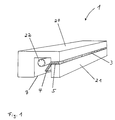
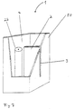
- Fig. 1 represents a specific embodiment of the invention Component in the form of a step, where this stair step both for indoor use and for the outdoor area is suitable.
- the step is with one Step surface 20 and a front surface 21 cast from concrete. Inside the step, a cavity 7 is designed, the side is accessible.
- the light transmission medium from a transparent Plastic material is 3 with its interface arranged flush with the front surface 21.
- the board-shaped light transmission medium comprises a first section 4 as well a second section 5, which has an angular section are interconnected.
- the entire light transmission medium, that extends along the entire staircase, can be produced using an injection molding process, for example become.
- the second section 4 of the light transmission medium protrudes into the cavity 7.
- tubular lighting device 22 which a Includes a large number of glow lamps arranged in a row.
- the Electric lighting device 22 is not shown in Way to a power supply of 230 volts AC connected.
- the electrical power required is in of the order of 1 watt per meter of longitudinal extension of the "Light tube”.
- the component can also be a "light tube” one behind the other have arranged light-emitting diodes, the energy consumption compared to the first described "light tube” is significantly lower.
- To further guide the light in the plastic material are to support in a special embodiment of the Invention the large areas of the light transmission medium shown in Fig. 1 coated with a material which a lower refractive index than the light transmission medium so that a total reflection on these large ones Side surfaces is made possible and thus in section 4 recorded light to a significant extent to the light emitting Surface section 3 are transported can.
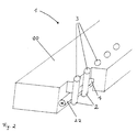
- Fig. 2 shows another in a broken representation Stair step as component 1 according to the invention, the light-emitting section 3 not in the front surface but lies in the step surface 20. Since sections 3 are part of the Tread, they are hard sealed.
- Light transmission media 2 arranged in extend the step into cavity 7, which is a tubular light source 22 already described with a variety of LEDs.
- This single "light tube” therefore supplies all individual light transmission media with light that can be directed to the respective interfaces is.
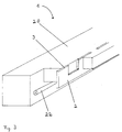
- Fig. 3 is a third embodiment of a step shown according to the invention.
- the light transmission medium 2 here has a board-like shape, with equidistant Intervals breakouts are shaped so that there is a comb-like structure results.
- the end faces of the comb teeth correspond to the light-emitting surface sections 3.
- the light is again from LEDs in a "light tube" 22 emitted and from the lower portion of the light transmission medium recorded and transferred to interface 3, so that a viewer in a longitudinal extension parallel to the edge of the Stairs glowing and equidistantly spaced rectangles sees what the desired notification function is implemented.
- the steps described can be darkened in particular used premises such as cinemas or the like be used.
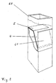
- the area shown in FIG. 4 covers a completely different area Component according to the invention in the form of a U-profile Corten steel, which can be inserted into a plaster.
- the U profile 30 takes the light transmission medium between the legs 2, which lies flush against the legs.
- the seal of the profile with the light transmission medium 2 takes place with an adhesive. Both parts thus form a cavity 7, the again takes up a "light tube” 22.
- the light transmission medium is corresponding to the color impression colored.
- To prevent light directly from the light source is emitted to the light-emitting surface the "light tube” 22 through an opaque cover strip 33 shadowed. The light only comes in later Reflection or scattering on the inside of the U-profile 30 to the light-emitting surface of the light guide medium 2.
- the U-profile 30 is welded to a rectangular profile 31 on both sides, which each has a flange 32.
- the Distance between the flange 32 and the light-emitting surface 3 of the light transmission medium essentially corresponds the height of the paving stones, making the paving stones rest on the flange 32 and thus the component in its Fix the whole in the plaster.
- the flange is direct is arranged parallel to the base 34 of the U-profile, so that the Base rests on the plaster base and thus the component how a patch element can be put on.
- the component shown in Fig. 4 is basically in any length possible. To achieve the desired one Several such elements can also act as a signal or side by side, especially with different ones Color donations. The described contribution in a plaster also allows driving over the invention Component with a vehicle.
- FIG. 5 Another component 1 that can be inserted into a plaster is shown Fig. 5. Again, between the legs of a U-section 30 a light transmission medium extending over the length of the U-profile 2 arranged. In the shown in Fig. 5 Embodiment, however, the light transmission medium 2 runs up to base 34 of the U-profile, making it more resilient the light-emitting interface 3 is provided can be. Thanks to the special design of the U-profile the leg ends 35 running inward to the base is in each case between an outer leg 37 and a longitudinal side wall section 36 of the light transmission medium 2 to its creates a cavity 7 on both sides, which has a “light tube” 22 records. The leg ends 35 cover the "light tube” 22, so that light only reaches the Surface 3 can reach.
- the component 1 can be in again a patch should be placed, with several attached to the U-profile attached T-profiles 31, of which only one is shown, for Serve fixation in the plaster.
- radiation sources emitting in UV are arranged in the cavity 7 and the light transmission medium 2 has a fluorescent substance in the body, which the converts recorded UV radiation into visible light, which leaves the light transmission medium 2 via the surface 3.
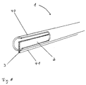
- the cylindrical handrail 40 has one extending into the interior of the handrail Light transmission medium 2 in the form of an elongated, flat Boards on.
- the light transmission medium protrudes above the Surface of the cylindrical handrail 40 so that a side surface 41 protrudes from the handrail.
- At the inside of the hollow handrail is one not shown in the figure "LED tube” arranged, so that from the diodes Light emitted in the tube from the light transmission medium 2 recorded and from this to the stepped, outer edge is led outside the handrail where the light is outside is delivered.
- the light transmission medium that can be formed by heating is also adaptable to bends in the handrail.
- a signaling, i.e. light emitting, edge in the form of Interface 3 are provided because ambient light, which via the side surface 41 into the light transmission medium occurs, from this at least partially to the interface 3 is guided and there leaves the light transmission medium.
- FIG. 7 Another component 1 according to the invention, in particular is stackable for designing walls, is shown in Fig. 7. It consists of a cuboid, hollow body 50 made of wood, in which the "light tube” or the Light transmission medium in the manner already described is introduced. To simplify the illustration, the not necessary facilities for connecting the components shown. Such a component is of course also from Plastic or metal can be produced.
- FIG. 8 shows a columnar component 60 that does not have its own Has light source.
- a light transmission medium is again in the hollow body 2 arranged that with an interface flush with the back surface of the cuboid in the picture Pillar lies.
- a Light window 61 arranged in the form of a glass pane what ambient light on the first section 4 of the light transmission medium can fall.
- the effect of total reflection becomes at least part of light through the second section 5 of the light transmission medium passed through to the interface where there is the device leaves.
- a stone bollard is provided with a hollow space along the axis.
- a disk-shaped light transmission medium the outer radius of which corresponds to the radius of the cylindrical bollard, is arranged in the bollard so that its two longitudinal axes coincide.
- a lamp is arranged in the cavity in such a way that the disk-shaped light transmission medium emits homogeneous light at an angle of 2 ⁇ in the region of its circumference for carrying out a signal or information function.
- optical devices that take advantage of the light refraction or reflection optimized from the light source to transmit the first section of the light transmission medium, so that as much light as possible into the light transmission medium is coupled.
- Such light deflecting devices include, for example, mirrors or lenses, in particular Fresnel lenses.
Landscapes
- Physics & Mathematics (AREA)
- Engineering & Computer Science (AREA)
- General Physics & Mathematics (AREA)
- Optics & Photonics (AREA)
- Architecture (AREA)
- Civil Engineering (AREA)
- Structural Engineering (AREA)
- Theoretical Computer Science (AREA)
- General Engineering & Computer Science (AREA)
- Life Sciences & Earth Sciences (AREA)
- Sustainable Development (AREA)
- Non-Portable Lighting Devices Or Systems Thereof (AREA)
- Illuminated Signs And Luminous Advertising (AREA)
Applications Claiming Priority (2)
| Application Number | Priority Date | Filing Date | Title |
|---|---|---|---|
| DE10004783 | 2000-02-03 | ||
| DE10004783A DE10004783A1 (de) | 2000-02-03 | 2000-02-03 | Bauelemente mit Leuchtkante |
Publications (2)
| Publication Number | Publication Date |
|---|---|
| EP1122487A2 true EP1122487A2 (fr) | 2001-08-08 |
| EP1122487A3 EP1122487A3 (fr) | 2001-08-16 |
Family
ID=7629735
Family Applications (1)
| Application Number | Title | Priority Date | Filing Date |
|---|---|---|---|
| EP01102149A Withdrawn EP1122487A3 (fr) | 2000-02-03 | 2001-02-01 | Composants avec support de transmission de lumière |
Country Status (2)
| Country | Link |
|---|---|
| EP (1) | EP1122487A3 (fr) |
| DE (1) | DE10004783A1 (fr) |
Cited By (4)
| Publication number | Priority date | Publication date | Assignee | Title |
|---|---|---|---|---|
| EP1637656A1 (fr) * | 2004-09-20 | 2006-03-22 | Behrendt Lichtdesign GmbH | Arrangement pour l'integration de diodes électroluminescentes dans des surfaces à marquer, de préférence des surfaces d'ouvrage |
| EP3141796A1 (fr) * | 2015-09-10 | 2017-03-15 | Schott AG | Éclairage lineaire |
| EP3865762A1 (fr) * | 2020-02-17 | 2021-08-18 | Lhotellier SA | Système et procédé d éclairage de l espace ambiant, et programme d ordinateur associé |
| EP3967183B1 (fr) * | 2020-09-15 | 2026-04-22 | Nolte Küchen GmbH & Co. KG | Meuble avec profil illuminé |
Families Citing this family (3)
| Publication number | Priority date | Publication date | Assignee | Title |
|---|---|---|---|---|
| DE20007434U1 (de) | 2000-04-22 | 2000-07-20 | Hess Form & Licht Gmbh & Co | Lichtpoller |
| DE10223245B4 (de) * | 2002-05-21 | 2014-02-27 | Zumtobel Staff Gmbh | Leuchte |
| DE102017208999B4 (de) | 2017-05-29 | 2025-09-04 | Volkswagen Aktiengesellschaft | Beleuchtungsvorrichtung mit einem im Querschnitt G-artig ausgebildeten und im Querschnitt aus zwei jeweils einseitig geöffneten Profilen gebildeten Gehäuse zur Beleuchtung des Innenraums eines Kraftfahrzeugs |
Citations (4)
| Publication number | Priority date | Publication date | Assignee | Title |
|---|---|---|---|---|
| EP0021308A1 (fr) * | 1979-06-29 | 1981-01-07 | Siemens Aktiengesellschaft | Dispositif pour augmenter la luminosité de dispositifs d'affichage passifs |
| DE4101098A1 (de) * | 1991-01-16 | 1992-07-23 | Peter Josef Korzilius Soehne G | Einbauleuchte |
| DE29720292U1 (de) * | 1997-11-07 | 1998-01-15 | Osa Elektronik Gmbh | Lichtleit- und Orientierungselement |
| EP0898030A1 (fr) * | 1997-08-21 | 1999-02-24 | Santo Kagaku Co., Ltd. | Elément antidérapant d'escalier |
Family Cites Families (2)
| Publication number | Priority date | Publication date | Assignee | Title |
|---|---|---|---|---|
| US2297851A (en) * | 1939-08-03 | 1942-10-06 | Western Union Telegraph Co | Illuminated display device |
| US3264462A (en) * | 1964-09-15 | 1966-08-02 | Independent Lock Co | Key display device |
-
2000
- 2000-02-03 DE DE10004783A patent/DE10004783A1/de not_active Withdrawn
-
2001
- 2001-02-01 EP EP01102149A patent/EP1122487A3/fr not_active Withdrawn
Patent Citations (4)
| Publication number | Priority date | Publication date | Assignee | Title |
|---|---|---|---|---|
| EP0021308A1 (fr) * | 1979-06-29 | 1981-01-07 | Siemens Aktiengesellschaft | Dispositif pour augmenter la luminosité de dispositifs d'affichage passifs |
| DE4101098A1 (de) * | 1991-01-16 | 1992-07-23 | Peter Josef Korzilius Soehne G | Einbauleuchte |
| EP0898030A1 (fr) * | 1997-08-21 | 1999-02-24 | Santo Kagaku Co., Ltd. | Elément antidérapant d'escalier |
| DE29720292U1 (de) * | 1997-11-07 | 1998-01-15 | Osa Elektronik Gmbh | Lichtleit- und Orientierungselement |
Cited By (8)
| Publication number | Priority date | Publication date | Assignee | Title |
|---|---|---|---|---|
| EP1637656A1 (fr) * | 2004-09-20 | 2006-03-22 | Behrendt Lichtdesign GmbH | Arrangement pour l'integration de diodes électroluminescentes dans des surfaces à marquer, de préférence des surfaces d'ouvrage |
| EP3141796A1 (fr) * | 2015-09-10 | 2017-03-15 | Schott AG | Éclairage lineaire |
| EP3141797A1 (fr) * | 2015-09-10 | 2017-03-15 | Schott AG | Éclairage lineaire |
| EP3346181A1 (fr) * | 2015-09-10 | 2018-07-11 | Schott Ag | Éclairage lineaire |
| US10569699B2 (en) | 2015-09-10 | 2020-02-25 | Schott Ag | Linear illumination device |
| EP3865762A1 (fr) * | 2020-02-17 | 2021-08-18 | Lhotellier SA | Système et procédé d éclairage de l espace ambiant, et programme d ordinateur associé |
| FR3107335A1 (fr) * | 2020-02-17 | 2021-08-20 | Lhotellier Sa | Système et procédé d’éclairage de l’espace ambiant, et programme d’ordinateur associé |
| EP3967183B1 (fr) * | 2020-09-15 | 2026-04-22 | Nolte Küchen GmbH & Co. KG | Meuble avec profil illuminé |
Also Published As
| Publication number | Publication date |
|---|---|
| EP1122487A3 (fr) | 2001-08-16 |
| DE10004783A1 (de) | 2001-08-09 |
Similar Documents
| Publication | Publication Date | Title |
|---|---|---|
| DE68927279T2 (de) | Schild mit elektrischer Beleuchtung aus einer Niederspannungsquelle | |
| EP1555477B1 (fr) | Luminaire comprenant des sources lumineuses de différentes couleurs ainsi qu'un guide de lumière plan pour émettre un mélange de lumières | |
| DE3542292A1 (de) | Leuchte fuer ein kraftfahrzeug | |
| DE4208922C1 (en) | Flat display background illuminator - has plastics-sealed PCB housing which displays by reflection using diffusing glass in sealing material | |
| EP1379742B1 (fr) | Meuble urbain presentant une vitre eclairee | |
| WO1999023413A1 (fr) | Appareil d'eclairage pour piscines et analogue | |
| DE10128689A1 (de) | Bauelement für einen begehbaren und/oder befahrbaren Bereich | |
| EP0676362B1 (fr) | Dispositif d'éclairage à fibres optiques pour escaliers roulant ou tapis roulant | |
| EP1122487A2 (fr) | Composants avec support de transmission de lumière | |
| DE102007059561A1 (de) | Leuchtende Glaswand | |
| DE19946079B4 (de) | Signalleuchte eines Kraftfahrzeugs | |
| AT6831U1 (de) | Beleuchtungsvorrichtung, insbesondere für strassen, wege, plätze od. dgl. | |
| EP1399692B1 (fr) | Element constitutif pour zone pouvant etre empruntee a pied et/ou a bord d'un vehicule | |
| WO2012055519A1 (fr) | Dispositif d'éclairage pour la zone extérieure | |
| DE69736907T2 (de) | Lichtemittierendes kabel oder ähnliches band | |
| DE202010006973U1 (de) | Baugruppe für einen Schrankenarm | |
| DE4101098A1 (de) | Einbauleuchte | |
| DE20105323U1 (de) | Möbel | |
| EP2642470A2 (fr) | Elément d'éclairage en forme de plaque et lampe dotée d'un élément d'éclairage | |
| DE9106859U1 (de) | Pollerleuchte | |
| DE19503430A1 (de) | Bauelement aus Kunststein und Verfahren zu seiner Herstellung | |
| DE202005001507U1 (de) | Oberflächenleuchtsystem | |
| EP2485208B1 (fr) | Corps d'éclairage | |
| DE2718352C2 (de) | Leitpfosten für Fahrbahnen | |
| DE9113944U1 (de) | Hinweisleuchte |
Legal Events
| Date | Code | Title | Description |
|---|---|---|---|
| PUAI | Public reference made under article 153(3) epc to a published international application that has entered the european phase |
Free format text: ORIGINAL CODE: 0009012 |
|
| PUAL | Search report despatched |
Free format text: ORIGINAL CODE: 0009013 |
|
| AK | Designated contracting states |
Kind code of ref document: A2 Designated state(s): AT BE CH DE LI NL Kind code of ref document: A2 Designated state(s): AT BE CH CY DE DK ES FI FR GB GR IE IT LI LU MC NL PT SE TR |
|
| AX | Request for extension of the european patent |
Free format text: AL;LT;LV;MK;RO;SI |
|
| AK | Designated contracting states |
Kind code of ref document: A3 Designated state(s): AT BE CH CY DE DK ES FI FR GB GR IE IT LI LU MC NL PT SE TR |
|
| AX | Request for extension of the european patent |
Free format text: AL;LT;LV;MK;RO;SI |
|
| AKX | Designation fees paid | ||
| 17P | Request for examination filed |
Effective date: 20020214 |
|
| RBV | Designated contracting states (corrected) |
Designated state(s): AT BE CH DE LI NL |
|
| REG | Reference to a national code |
Ref country code: DE Ref legal event code: 8566 |
|
| RAP1 | Party data changed (applicant data changed or rights of an application transferred) |
Owner name: KOMBILITH ENTWICKLUNGS- UND VERWERTUNGSGESELLSCHAF |
|
| RAP1 | Party data changed (applicant data changed or rights of an application transferred) |
Owner name: CARL CROON GMBH & CO. KG BAUELEMENTEHANDEL Owner name: KOMBILITH ENTWICKLUNGS- UND VERWERTUNGSGESELLSCHAF |
|
| STAA | Information on the status of an ep patent application or granted ep patent |
Free format text: STATUS: THE APPLICATION IS DEEMED TO BE WITHDRAWN |
|
| 18D | Application deemed to be withdrawn |
Effective date: 20060829 |