EP1122495B1 - Dispositif pour l'incinération de matière biomasse particulaire et solide - Google Patents
Dispositif pour l'incinération de matière biomasse particulaire et solide Download PDFInfo
- Publication number
- EP1122495B1 EP1122495B1 EP01101502A EP01101502A EP1122495B1 EP 1122495 B1 EP1122495 B1 EP 1122495B1 EP 01101502 A EP01101502 A EP 01101502A EP 01101502 A EP01101502 A EP 01101502A EP 1122495 B1 EP1122495 B1 EP 1122495B1
- Authority
- EP
- European Patent Office
- Prior art keywords
- gas
- blower
- space
- wall
- dust
- Prior art date
- Legal status (The legal status is an assumption and is not a legal conclusion. Google has not performed a legal analysis and makes no representation as to the accuracy of the status listed.)
- Expired - Lifetime
Links
- 239000002028 Biomass Substances 0.000 title description 9
- 239000007787 solid Substances 0.000 title description 7
- 239000000463 material Substances 0.000 title description 2
- 239000007789 gas Substances 0.000 claims abstract description 97
- 238000002485 combustion reaction Methods 0.000 claims abstract description 48
- 238000002156 mixing Methods 0.000 claims description 51
- 239000000428 dust Substances 0.000 claims description 35
- 238000010276 construction Methods 0.000 claims 1
- 238000007789 sealing Methods 0.000 claims 1
- 239000000203 mixture Substances 0.000 abstract description 5
- 239000003570 air Substances 0.000 description 38
- 238000010304 firing Methods 0.000 description 27
- 238000002347 injection Methods 0.000 description 8
- 239000007924 injection Substances 0.000 description 8
- 239000002023 wood Substances 0.000 description 8
- UGFAIRIUMAVXCW-UHFFFAOYSA-N Carbon monoxide Chemical compound [O+]#[C-] UGFAIRIUMAVXCW-UHFFFAOYSA-N 0.000 description 4
- 239000003546 flue gas Substances 0.000 description 4
- 239000000446 fuel Substances 0.000 description 4
- 150000002430 hydrocarbons Chemical class 0.000 description 4
- 239000001301 oxygen Substances 0.000 description 4
- 229910052760 oxygen Inorganic materials 0.000 description 4
- 230000007704 transition Effects 0.000 description 4
- QVGXLLKOCUKJST-UHFFFAOYSA-N atomic oxygen Chemical compound [O] QVGXLLKOCUKJST-UHFFFAOYSA-N 0.000 description 3
- 238000001816 cooling Methods 0.000 description 3
- 238000011161 development Methods 0.000 description 3
- 230000018109 developmental process Effects 0.000 description 3
- 229930195733 hydrocarbon Natural products 0.000 description 3
- JEIPFZHSYJVQDO-UHFFFAOYSA-N iron(III) oxide Inorganic materials O=[Fe]O[Fe]=O JEIPFZHSYJVQDO-UHFFFAOYSA-N 0.000 description 3
- 238000004519 manufacturing process Methods 0.000 description 3
- 238000009825 accumulation Methods 0.000 description 2
- 238000004891 communication Methods 0.000 description 2
- 238000005516 engineering process Methods 0.000 description 2
- VNWKTOKETHGBQD-UHFFFAOYSA-N methane Chemical compound C VNWKTOKETHGBQD-UHFFFAOYSA-N 0.000 description 2
- 230000001105 regulatory effect Effects 0.000 description 2
- 230000003716 rejuvenation Effects 0.000 description 2
- 239000004215 Carbon black (E152) Substances 0.000 description 1
- 206010053615 Thermal burn Diseases 0.000 description 1
- 239000012080 ambient air Substances 0.000 description 1
- 230000015572 biosynthetic process Effects 0.000 description 1
- 238000007664 blowing Methods 0.000 description 1
- 238000003763 carbonization Methods 0.000 description 1
- 239000003610 charcoal Substances 0.000 description 1
- 239000011362 coarse particle Substances 0.000 description 1
- 238000005336 cracking Methods 0.000 description 1
- 230000001419 dependent effect Effects 0.000 description 1
- 238000009795 derivation Methods 0.000 description 1
- 230000003467 diminishing effect Effects 0.000 description 1
- 239000012717 electrostatic precipitator Substances 0.000 description 1
- 239000003344 environmental pollutant Substances 0.000 description 1
- 238000000605 extraction Methods 0.000 description 1
- 239000012530 fluid Substances 0.000 description 1
- 238000010438 heat treatment Methods 0.000 description 1
- 238000000034 method Methods 0.000 description 1
- 239000013618 particulate matter Substances 0.000 description 1
- 231100000719 pollutant Toxicity 0.000 description 1
- 230000000750 progressive effect Effects 0.000 description 1
- 238000011084 recovery Methods 0.000 description 1
- 238000009420 retrofitting Methods 0.000 description 1
- 239000002893 slag Substances 0.000 description 1
- 239000000243 solution Substances 0.000 description 1
- 230000000087 stabilizing effect Effects 0.000 description 1
- 239000002699 waste material Substances 0.000 description 1
Images



Classifications
-
- F—MECHANICAL ENGINEERING; LIGHTING; HEATING; WEAPONS; BLASTING
- F23—COMBUSTION APPARATUS; COMBUSTION PROCESSES
- F23G—CREMATION FURNACES; CONSUMING WASTE PRODUCTS BY COMBUSTION
- F23G5/00—Incineration of waste; Incinerator constructions; Details, accessories or control therefor
- F23G5/50—Control or safety arrangements
-
- F—MECHANICAL ENGINEERING; LIGHTING; HEATING; WEAPONS; BLASTING
- F23—COMBUSTION APPARATUS; COMBUSTION PROCESSES
- F23G—CREMATION FURNACES; CONSUMING WASTE PRODUCTS BY COMBUSTION
- F23G5/00—Incineration of waste; Incinerator constructions; Details, accessories or control therefor
- F23G5/32—Incineration of waste; Incinerator constructions; Details, accessories or control therefor the waste being subjected to a whirling movement, e.g. cyclonic incinerators
-
- F—MECHANICAL ENGINEERING; LIGHTING; HEATING; WEAPONS; BLASTING
- F23—COMBUSTION APPARATUS; COMBUSTION PROCESSES
- F23G—CREMATION FURNACES; CONSUMING WASTE PRODUCTS BY COMBUSTION
- F23G7/00—Incinerators or other apparatus for consuming industrial waste, e.g. chemicals
- F23G7/10—Incinerators or other apparatus for consuming industrial waste, e.g. chemicals of field or garden waste or biomasses
-
- F—MECHANICAL ENGINEERING; LIGHTING; HEATING; WEAPONS; BLASTING
- F23—COMBUSTION APPARATUS; COMBUSTION PROCESSES
- F23G—CREMATION FURNACES; CONSUMING WASTE PRODUCTS BY COMBUSTION
- F23G2203/00—Furnace arrangements
- F23G2203/40—Stationary bed furnace
-
- F—MECHANICAL ENGINEERING; LIGHTING; HEATING; WEAPONS; BLASTING
- F23—COMBUSTION APPARATUS; COMBUSTION PROCESSES
- F23G—CREMATION FURNACES; CONSUMING WASTE PRODUCTS BY COMBUSTION
- F23G2209/00—Specific waste
- F23G2209/26—Biowaste
- F23G2209/261—Woodwaste
-
- F—MECHANICAL ENGINEERING; LIGHTING; HEATING; WEAPONS; BLASTING
- F23—COMBUSTION APPARATUS; COMBUSTION PROCESSES
- F23G—CREMATION FURNACES; CONSUMING WASTE PRODUCTS BY COMBUSTION
- F23G2900/00—Special features of, or arrangements for incinerators
- F23G2900/50007—Co-combustion of two or more kinds of waste, separately fed into the furnace
-
- F—MECHANICAL ENGINEERING; LIGHTING; HEATING; WEAPONS; BLASTING
- F23—COMBUSTION APPARATUS; COMBUSTION PROCESSES
- F23G—CREMATION FURNACES; CONSUMING WASTE PRODUCTS BY COMBUSTION
- F23G2900/00—Special features of, or arrangements for incinerators
- F23G2900/54402—Injecting fluid waste into incinerator
Definitions
- the invention relates to a device for burning of Organic dust and organic solids.
- Biomass used for heating and for thermal disposal are available, for example, piece wood, shavings, Sawdust, wood chips, biofin dusts and biowaste.
- the progressive development of manufacturing technologies in the woodworking industry has not just shortened Workpiece life, but also to a considerable extent resulted in finer, dusty production waste in the Industry and craft today account for 70 to 80% (Percent) of wood residues.
- Another user wood burning is the bakery trade. The burning such residues is a challenge to the Feuerungsbauer. The regularly used rust with additional Primary air addition achieved in most combustion plants no longer the required low emission levels.
- EP-A-0 877 201 A generic device of the type mentioned is known from EP-A-0 877 201. Between the helical gas flow generating blower device and the firing space fluidly connected thereto a channel-like mixing space formed to the Firebox opens. Comparable is also the EP-A-0 905 442.
- the invention is based on the object, starting from the As described above, a device for burning organic dust masses and organic solid matter specify the least polluting pollutants arise and be emitted.
- the downstream cross-sectional taper of the mixing chamber with the approximately central gas passage opening causes a Constriction of the mixed gas combustion air rotating in the mixing chamber.
- This constricted combustion air relaxes in the downstream firebox in one stable rotating fire roller.
- This fire roller can thereby targeted to the ember bed surface in the firebox be directed. This ultimately causes an optimal and rapid combustion of biomass in the firebox.
- the baffle plate formed in the present example as a heat shield may have a central opening.
- the gases flowing back from the combustion chamber into the mixing chamber are thus not completely deflected radially outwards on the baffle plate, but partly flow directly back into the blower device and then back into the mixing chamber via the annular space. This has a stabilizing effect on the rotating gas cylinder in the mixing chamber and can also be referred to as internal NO x reduction.
- the device according to the invention means for the woodworking Industry and the bakery trade a big one technical progress in terms of thermal Energy generation and disposal of the residues.
- Old and new biomass firings can be combined with the equipped device according to the invention or be retrofitted.
- a device according to the invention can with a through a frequency converter regulated link head blower according to EP 0 344 498 or with operated an impeller with perforated blading become.
- the fresh air can be sucked in the shaft flange area and be used for engine cooling.
- Fresh air can also supplied to the blower area via separate intake openings, rotated and compactly accelerated.
- the according to rotating fresh air is then over a Annulus fed to the mixing chamber, in addition to from the Combustion chamber recirculated hot gas mixed and then the Supplied combustion process.
- blower area and mixing room can be a component in itself firmly connected "gas mixer" arise.
- the Firebox is fluidly gas mixer downstream.
- the transition area or border area between this gas mixer tap and the firebox preferably formed water-cooled.
- the coldest zone This gas mixer is located in the blower area.
- the warmer zone lies in the mixing room.
- Large-area emerging gas swirl nozzle is the prevailing Accumulation heat (about 900 ° C (degrees Celsius)) of the downstream Firing room exposed.
- the in the mixing chamber radially rotating gas mass generates in the center one very strong gas vacuum - eye of an eddy current - what to a backflow of CO-containing hot gas from the firebox leads to the inner baffle plate, which for the sake of a increased thermal load formed as a heat shield can be.
- the CO-laden substream heats the gases in the Mixing room at about 200 to 300 ° C (degrees Celsius).
- the Temperature In the border area between mixing room and firebox lies the Temperature at about 500 ° C to 700 ° C (degrees Celsius).
- the communication zone created by the previously known link head blower the gas flow with the supply air or Ambient air is in the periphery of the annulus, on the inside of the chamber wall.
- the inventively created Communication zone is located with a significantly improved efficiency, however, at the end of the new existing mixing chamber according to a first embodiment of the invention in the cross-sectional area of the swirl nozzle acting gas passage opening in the region of a concentric Rejuvenation of the mixing room in its transition to Firing room, or according to another embodiment of the Invention in the annular gap of the gas passage opening containing annular wall.
- the hot gas roller thus produced leaves in the downstream, existing or retrofitted firing rooms a staufenlose Low-emission combustion of biomass in the control range from 30% to 100% with the necessary temperature mixing and dwell time too.
- By changing the cross sections from the inner heat shield or the swirl nozzle can the spiral radial flow in the firing areas the respective requirements, in particular the Location, shape and size of an ember bed to be adjusted.
- the each resulting spiral, rotating radial flow-type fire roller can last longer due to these changes and more constant or shorter and more unstable with respect to her Rotational form be designed.
- the device according to the invention can be vertical, horizontal or diagonally, as injection and / or underfeed firing be educated.
- a secondary air addition and part of a primary air addition can be done via the swirl nozzle, in one spirally rotating gas cylinder in the axial outflow direction towards the ember bed.
- Another primary air addition in the Front lower firebed area can be accessed via gas exhaust nozzles done in the front wall of the outer Heat shield can be placed. Your air jet can then end and act in the ember bed in the axial outflow direction, especially in the lower part of the ember bed.
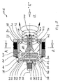
- a firing system 10 is used for burning organic dust masses and organic solids.
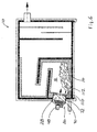
- the furnace 10 has a firing space 12, in the solid masses 14 (Fig. 6) can be burned.
- a gas mixer 20 produces a gas cylinder 90 and represents a compact unit, which in a in the Wall 22 of the furnace 10 existing breakthrough 24 is used gas-tight.
- the gas mixer 20 has an outer housing wall 26 which is in its central area is formed circular cylindrical and a mixing chamber 28th wrapped in a cylindrical shape.
- a central opening in which a shaft 32 rotatably mounted is, via a motor drive 34 about the longitudinal axis 36 of the gas-mixing mixer 20 are set in rotation can.
- On the shaft 32 are in the present case two rings attached by chain links 38, 40, which together with the Shaft 32 can rotate about the axis 36.
- the wreaths are movably attached to the shaft 32.
- Outflow side in the transition area between the blower area 46 and the mixing chamber 28, is a centric heat shield 50 available.
- the heat shield 50 On its inflow side is the heat shield 50 surrounded by a housing 52.
- In this case 52 projects into a conduit 54, which the fan area 46th and the back wall 30 pierces.
- the opening 56 of this Line 54 provides a suction for fresh air and Rezigas dar. Fresh air and Rezigas can so through the Line 42 (in the fan section 46) and through the line 54 (in the region of the housing 52 of the heat shield 50) each initiated.
- the housing 52 has opening slots 58 through which the in the housing 52 introduced mixture of fresh air and Rezigas can emerge radially in an annular space 60, the Heat shield 50 radially outwardly surrounds.
- the annulus 60 is so formed between the heat shield 50 and the housing wall 26 and adjusts the fluid connection to Mixing room 28 dar.
- annular wall 70 formed as an outer heat shield is.
- the annular wall 70 has a central opening 72. Die Inside the annular wall 70 is in a flowing transition connected to the housing wall 26. This on the ring wall 70th adjacent housing wall portion 78 is connected to the housing wall 26th integrally connected.
- the metallic in this case Housing wall 26 thus forms in the region of the annular wall 70 a inner lining of this annular wall 70.
- Fig. 1st right side of this ring wall 70 is the Furnace space 12, in particular of FIG. 6 schematically can be seen.
- full-surface Heat shield 50 is shown in the in Fig. 2 in section Heat shield 50.2 a central opening 62 available. This allows a certain flow compensation between the Blower area 46 and the mixing space 28 take place. Instead of an opening 62 can also be arranged a plurality of openings be.
- furnace 10.5 are fed the bio-dust masses via a blowing-in line 18 (Arrow 16).
- the sparger 18 is in this embodiment Component of the gas mixer 20.
- the injection line 18 protrudes largely centrally through the Mixing chamber 28 through and ends in the region of the opening 72nd With her other end, she pierces the heat shield 50 and the housing 52 and ends outside the rear wall 30th
- the firing system 10 or 10.5 works following way:
- a rotating air roller is generated in the region of the annular space 60, which continues on the inside of the housing wall 26 through the mixing space 28 as a gas roller 90.
- this gas cylinder 90 experiences a central constriction (gas roller 90.2).
- this gas cylinder 90.2 relaxes more or less abruptly to the outside.
- a radially expanding hot gas roller (fire roller) 90.4 is created which ends above the ember bed of the solid mass 14 (FIG. 6). Due to the strong rotation of this gas cylinder 90, 90.2, 90.4 forms in the region of its axis of rotation, a significant negative pressure.
- a gas backflow (arrow 100) is effected which returns CO laden hot gas as a partial flow from the firing chamber 12 into the region of the mixing chamber 28.
- This gas recirculation 100 heats the gases in the mixing chamber to about 200 to 300 ° C (degrees Celsius), the gases in the region of the opening 72 to about 500 to 700 ° C.
- the gas recirculation 100 is completely deflected outwards (arrows 104) and mixes with the gas cylinder 90.
- FIG 2 FIG 2
- Openings 110 present through the air from the Mixing chamber 28 in the firing chamber 12 as a result of by the Gas roll 90 flow through the mixing chamber 28 generated gas flow can.
- the openings 110 are aligned so that this additionally directed into the firing chamber 12 gas flow (Primary air) in the direction of the solid mass 14 or whose ember bed 112 is directed.
- Fig. 7 is a compared to the embodiments shown in FIGS. 1 and 5 comparatively very thick wall 70.7 available. This allows a constricted longer in the flow direction permanent gas or fire roller 90.4 achieve.
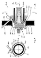
- Fig. 8 In the furnace 10.8 shown in Fig. 8 is the in the above-described furnace 10 existing Ring wall 70 as relatively far into the firing 12th protruding pipe or channel piece 70.8 formed. In addition, between this piece of pipe 70.8 and the combustion chamber 12 limiting wall 22 an annular gap 116 available.
- the injection line, in the Fig. 5 in the Mixing chamber 28 protrudes, is 10.8 in this furnace 10.8 outside the gas mixer 20 available by protrudes through the wall 22 and outside of the pipe section 70.8 ends directly in the firing chamber 12. Your end Injection nozzle for introducing coarse and in particular also Fine dust in the firing chamber 12, and thus its outlet opening 118, is aligned in the firing chamber 12 that the dust 120 is parallel to a pipe section 70.8 concentric can flow out surrounding circular cylinder.
- This furnace 10.8 is based on the knowledge that a coarse and fine dust combustion no constriction of Gas roller, as described in Figures 1 to 7 is needed.
- the ignition of coarse and fine dust 120 takes place immediately after leaving the injection line 18.8 and thus after flowing out of the outlet opening 118.
- the in the rotating gas or fire roller 90.8 in the firing chamber 12 immediately released heat accumulation allows a fast and optimal combustion without Grobasche- and Slag formation.
- the firing chamber 12 is due to the ruling high temperatures fireproof.
- the internal Rezigas recirculation and the NO x reduction are carried out in the same manner as in the ember bed furnace described above in connection with FIGS. 1 and 7.
- the externally recirculated flue gas with its oxygen content contributes all the more to the NO x reduction, the more unburned hydrocarbons (CO) are present in the externally recirculated Rezigas.
Landscapes
- Engineering & Computer Science (AREA)
- Mechanical Engineering (AREA)
- General Engineering & Computer Science (AREA)
- Environmental & Geological Engineering (AREA)
- Life Sciences & Earth Sciences (AREA)
- Sustainable Development (AREA)
- Sustainable Energy (AREA)
- Solid-Fuel Combustion (AREA)
- Incineration Of Waste (AREA)
- Structures Of Non-Positive Displacement Pumps (AREA)
- Air Bags (AREA)
Claims (19)
- Dispositif (10, 10.5, 10.8) pour l'incinération de matières biomasses particulaires et de matières biomasses solides (14, 16), comportant :caractérisé en ce que la chambre de mélange (28) comporte du côté de l'échappement un étranglement de sa section transversale pourvu d'un orifice à peu près central (72) de passage du gaz.une enceinte de chauffage ou de combustion (12),une installation de ventilation ou de soufflante (48) pour produire un tourbillon de feu en rotation (90, 90.2, 90.4, 90.8) dans l'enceinte de chauffage ou de combustion (12),un écran d'accumulation conçu en tant que bouclier thermique (50, 50.2) et délimitant, du côté de l'échappement, le dispositif de ventilation ou de soufflante, pour isoler au moins partiellement le dispositif de ventilation (48) des gaz chauds qui refoulent depuis l'enceinte de chauffage (12),un espace annulaire (60) qui entoure radialement l'écran d'accumulation,une paroi de cuve (26, 26.8) qui entoure extérieurement l'espace annulaire (60),une chambre de mélange (28) entre l'enceinte de chauffage (12) et le dispositif de ventilation via laquelle communiquent, sur le plan de l'écoulement, le dispositif de ventilation et l'enceinte de chauffage (12),
- Dispositif selon la revendication 1, caractérisé en ce qu'au moins une ouverture centrale (62) est ménagée dans l'écran d'accumulation ou encore dans le bouclier thermique (50.2).
- Dispositif selon l'une des revendications précédentes, caractérisé en ce que des ouvertures de passage ou de sortie du gaz (110) pour l'air sont ménagées dans la paroi circulaire (70) délimitant l'orifice de passage du gaz (72) de la chambre de mélange (28) de telle sorte que le courant d'air évacué par ces ouvertures de passage ou de sortie du gaz (110) est orienté vers le lit incandescent (112) disposé dans l'enceinte de chauffage.
- Dispositif selon l'une des revendications précédentes, caractérisé en ce qu'une fente annulaire (116) est prévue pour un tourbillon de gaz (90.8) provenant de la chambre de mélange (28) et s'écoulant dans l'enceinte de chauffage (12) dans la paroi circulaire (70.8) de la chambre de mélange comportant l'orifice de passage du gaz (72).
- Dispositif selon la revendication 4, caractérisé en ce que la paroi circulaire est conçue à la façon d'un élément de type canal ou tubulaire (70.8) qui pénètre dans l'enceinte de chauffage (12).
- Dispositif selon la revendication 4 ou 5, caractérisé en ce que l'élément de type canal ou tubulaire (70.8) est conçu de façon à être refroidi, en particulier refroidi par eau.
- Dispositif selon l'une des revendications précédentes, caractérisé en ce qu'au moins une ouverture centrale (62) est ménagée dans l'écran d'accumulation ou encore le bouclier thermique (50.2).
- Dispositif selon l'une des revendications précédentes, caractérisé en ce qu'il est prévu une conduite d'amenée (18, 18.8) destinée à amener les poussières grossières et fines dans l'enceinte de chauffage (12).
- Dispositif selon la revendication 8, caractérisé en ce que la conduite d'amenée (18) pour les poussières grossières et les poussières fines (16) débouche dans la chambre de mélange (28) ou dans la zone de l'orifice de passage du gaz (72).
- Dispositif selon la revendication 9, caractérisé en ce que la conduite d'amenée (18.8) pour les poussières grossières et les poussières fines (120) débouche dans l'enceinte de chauffage (12).
- Dispositif selon la revendication 10, caractérisé en ce que la zone d'extrémité de la conduite d'amenée (18.8) des poussières (120) est orientée avec son orifice de sortie (118) à peu près parallèlement à la paroi de l'élément de type canal ou tubulaire (70.8), de telle sorte que la poussière (120) s'écoule hors de l'orifice de sortie (118) dans une paroi en forme de cylindre circulaire orientée concentriquement à l'axe longitudinal (36) de l'élément de type canal ou tubulaire (70.8).
- Dispositif selon l'une des revendications précédentes, caractérisé en ce que le dispositif de ventilation (48) comporte au moins une ouverture d'aspiration (42, 56) pour l'air frais.
- Dispositif selon l'une des revendications précédentes, caractérisé en ce que le dispositif de ventilation (48) comporte au moins une ouverture d'aspiration (42, 56) pour le gaz recyclé ou de recirculation.
- Dispositif selon l'une des revendications précédentes, caractérisé en ce que la paroi de cuve ou de boítier qui entoure l'espace annulaire existe également dans la zone de la chambre de mélange (28) sous forme d'une paroi de séparation extérieure, de telle sorte qu'un élément de construction servant à générer le tourbillon de feu (90) est présent.
- Dispositif selon la revendication 14, caractérisé en ce que la paroi de cuve (26, 26.8, 78) s'étend jusqu'à l'orifice de passage du gaz (72).
- Dispositif selon l'une des revendications précédentes, caractérisé en ce que la paroi circulaire (70, 70.7, 70.8) délimitant l'orifice de passage du gaz (72) est conçue en tant que bouclier thermique extérieur.
- Dispositif selon l'une des revendications précédentes, caractérisé en ce que le dispositif de ventilation (48) comporte une roue de ventilateur ou de soufflante (32, 38, 40).
- Dispositif selon la revendication 17, caractérisé en ce que la roue de ventilateur ou de soufflante comporte un arbre central (32) et des éléments de type aube fixés à l'arbre de façon mobile (38, 40).
- Dispositif selon la revendication 18, caractérisé en ce que les éléments de type aube possèdent respectivement des éléments réciproquement mobiles (38, 40).
Applications Claiming Priority (2)
| Application Number | Priority Date | Filing Date | Title |
|---|---|---|---|
| DE20001926U | 2000-02-04 | ||
| DE20001926U DE20001926U1 (de) | 2000-02-04 | 2000-02-04 | Vorrichtung zum Verbrennen von Biofeinstaub- und Feststoffmassen |
Publications (2)
| Publication Number | Publication Date |
|---|---|
| EP1122495A1 EP1122495A1 (fr) | 2001-08-08 |
| EP1122495B1 true EP1122495B1 (fr) | 2005-03-23 |
Family
ID=7936813
Family Applications (1)
| Application Number | Title | Priority Date | Filing Date |
|---|---|---|---|
| EP01101502A Expired - Lifetime EP1122495B1 (fr) | 2000-02-04 | 2001-01-24 | Dispositif pour l'incinération de matière biomasse particulaire et solide |
Country Status (3)
| Country | Link |
|---|---|
| EP (1) | EP1122495B1 (fr) |
| AT (1) | ATE291722T1 (fr) |
| DE (2) | DE20001926U1 (fr) |
Families Citing this family (1)
| Publication number | Priority date | Publication date | Assignee | Title |
|---|---|---|---|---|
| CN111059556A (zh) * | 2019-12-31 | 2020-04-24 | 苏州如陆环保科技有限公司 | 一种高效催化燃烧设备 |
Family Cites Families (5)
| Publication number | Priority date | Publication date | Assignee | Title |
|---|---|---|---|---|
| DE3917049A1 (de) | 1989-05-25 | 1990-11-29 | Christian Geb Gaertner Priska | Vorrichtung zum verbrennen von bio- und feststoffmassen |
| DE4125047A1 (de) * | 1991-07-29 | 1993-02-04 | Paul Christian | Vorrichtung zur heissgasmischung und staubreduzierung in brennkammern |
| DE19525106C1 (de) * | 1995-06-29 | 1997-03-13 | Richard Kablitz & Mitthof Gmbh | Feuerungsanlage |
| DE29707893U1 (de) * | 1997-05-05 | 1997-06-26 | Christian, Paul, 74177 Bad Friedrichshall | Vorrichtung zum Verbrennen von Bio- und Feststoffmassen |
| DE19743338A1 (de) * | 1997-09-30 | 1999-04-01 | Koeb & Schaefer Kg | Feuerungsanlage |
-
2000
- 2000-02-04 DE DE20001926U patent/DE20001926U1/de not_active Expired - Lifetime
-
2001
- 2001-01-24 DE DE50105661T patent/DE50105661D1/de not_active Expired - Fee Related
- 2001-01-24 EP EP01101502A patent/EP1122495B1/fr not_active Expired - Lifetime
- 2001-01-24 AT AT01101502T patent/ATE291722T1/de not_active IP Right Cessation
Also Published As
| Publication number | Publication date |
|---|---|
| DE50105661D1 (de) | 2005-04-28 |
| ATE291722T1 (de) | 2005-04-15 |
| EP1122495A1 (fr) | 2001-08-08 |
| DE20001926U1 (de) | 2000-03-23 |
Similar Documents
| Publication | Publication Date | Title |
|---|---|---|
| DE60209759T2 (de) | Verbrennungsvorrichtung | |
| DE60015740T2 (de) | Biomassenverbrennungskammer für eine gasturbine | |
| DE2716216A1 (de) | Brenner fuer pulverfoermigen brennstoff | |
| DE102021210662B4 (de) | Vorrichtung und Verfahren zum Trocknen von Material sowie Asphaltmischanlage mit einer derartigen Vorrichtung | |
| DE60120787T2 (de) | Kombiniertes wirbelbett- und kohlenstaubverbrennungsverfahren | |
| DE2804513A1 (de) | Brenner | |
| DE4230311C1 (de) | Verfahren und Verbrennungsofen zum Verbrennen von Abfällen | |
| WO1988005494A1 (fr) | Combustion de charbon avec un foyer a lit fluidise | |
| DE2745756C3 (de) | Verbrennungsofen | |
| EP0952396B1 (fr) | Dispositif pour brûler des matériaux combustibles particulaires | |
| EP1122495B1 (fr) | Dispositif pour l'incinération de matière biomasse particulaire et solide | |
| EP0473618B1 (fr) | Dispositif de combustion de biomasses et de matieres solides | |
| DE202008009650U1 (de) | Mehrstoff-Brenner | |
| DE3126419C2 (de) | Feuerungsanlage für Stroh oder ähnliches Material | |
| CH671822A5 (en) | Solid fuel fired boiler - has after burning chamber connected to primary combustion chamber by mixing tube | |
| DE3524962C2 (fr) | ||
| EP1352197A1 (fr) | Bruleur pour la combustion de combustible pulverulent | |
| EP0525711A2 (fr) | Dispositif de combustion de biomasses et de matières solides | |
| DE19850376A1 (de) | Vorrichtung zum Verbrennen von Bio- und Feststoffmassen mit primärer Schadstoffminderung - CO, NOx und Staub | |
| WO1982000331A1 (fr) | Generateur de gaz chaud | |
| WO1989009364A1 (fr) | Appareil de combustion pour bruler des combustibles solides | |
| EP1162405A2 (fr) | Dispositif de combustion pour combustibles renouvelables granulés, notamment boulettes de bois | |
| EP0877201A1 (fr) | Dispositif pour la combustion de matières biologiques et solides | |
| DE102010051601A1 (de) | Heizkessel | |
| EP0180657B1 (fr) | Brûleur pour combutibles peu volatiles |
Legal Events
| Date | Code | Title | Description |
|---|---|---|---|
| PUAI | Public reference made under article 153(3) epc to a published international application that has entered the european phase |
Free format text: ORIGINAL CODE: 0009012 |
|
| AK | Designated contracting states |
Kind code of ref document: A1 Designated state(s): AT BE CH CY DE DK ES FI FR GB GR IE IT LI LU MC NL PT SE TR |
|
| AX | Request for extension of the european patent |
Free format text: AL;LT;LV;MK;RO;SI |
|
| 17P | Request for examination filed |
Effective date: 20020131 |
|
| AKX | Designation fees paid |
Free format text: AT BE CH CY DE DK ES FI FR GB GR IE IT LI LU MC NL PT SE TR |
|
| AXX | Extension fees paid |
Free format text: LT PAYMENT 20020131 |
|
| 17Q | First examination report despatched |
Effective date: 20030613 |
|
| RAP1 | Party data changed (applicant data changed or rights of an application transferred) |
Owner name: CHRISTIAN, PAUL Owner name: MUELLER AG HOLZFEUERUNGEN Owner name: VAN MEEGEN, GERHARD |
|
| RIN1 | Information on inventor provided before grant (corrected) |
Inventor name: CHRISTIAN, PAUL |
|
| GRAP | Despatch of communication of intention to grant a patent |
Free format text: ORIGINAL CODE: EPIDOSNIGR1 |
|
| RAP1 | Party data changed (applicant data changed or rights of an application transferred) |
Owner name: MUELLER AG HOLZFEUERUNGEN Owner name: VAN MEEGEN, GERHARD |
|
| GRAS | Grant fee paid |
Free format text: ORIGINAL CODE: EPIDOSNIGR3 |
|
| GRAA | (expected) grant |
Free format text: ORIGINAL CODE: 0009210 |
|
| AK | Designated contracting states |
Kind code of ref document: B1 Designated state(s): AT BE CH CY DE DK ES FI FR GB GR IE IT LI LU MC NL PT SE TR |
|
| AX | Request for extension of the european patent |
Extension state: LT |
|
| PG25 | Lapsed in a contracting state [announced via postgrant information from national office to epo] |
Ref country code: IT Free format text: LAPSE BECAUSE OF FAILURE TO SUBMIT A TRANSLATION OF THE DESCRIPTION OR TO PAY THE FEE WITHIN THE PRE;WARNING: LAPSES OF ITALIAN PATENTS WITH EFFECTIVE DATE BEFORE 2007 MAY HAVE OCCURRED AT ANY TIME BEFORE 2007. THE CORRECT EFFECTIVE DATE MAY BE DIFFERENT FROM THE ONE RECORDED.SCRIBED TIME-LIMIT Effective date: 20050323 Ref country code: GB Free format text: LAPSE BECAUSE OF FAILURE TO SUBMIT A TRANSLATION OF THE DESCRIPTION OR TO PAY THE FEE WITHIN THE PRESCRIBED TIME-LIMIT Effective date: 20050323 Ref country code: IE Free format text: LAPSE BECAUSE OF FAILURE TO SUBMIT A TRANSLATION OF THE DESCRIPTION OR TO PAY THE FEE WITHIN THE PRESCRIBED TIME-LIMIT Effective date: 20050323 Ref country code: FI Free format text: LAPSE BECAUSE OF FAILURE TO SUBMIT A TRANSLATION OF THE DESCRIPTION OR TO PAY THE FEE WITHIN THE PRESCRIBED TIME-LIMIT Effective date: 20050323 |
|
| REG | Reference to a national code |
Ref country code: GB Ref legal event code: FG4D Free format text: NOT ENGLISH |
|
| REG | Reference to a national code |
Ref country code: CH Ref legal event code: EP |
|
| REG | Reference to a national code |
Ref country code: IE Ref legal event code: FG4D Free format text: GERMAN |
|
| REF | Corresponds to: |
Ref document number: 50105661 Country of ref document: DE Date of ref document: 20050428 Kind code of ref document: P |
|
| PG25 | Lapsed in a contracting state [announced via postgrant information from national office to epo] |
Ref country code: GR Free format text: LAPSE BECAUSE OF FAILURE TO SUBMIT A TRANSLATION OF THE DESCRIPTION OR TO PAY THE FEE WITHIN THE PRESCRIBED TIME-LIMIT Effective date: 20050623 Ref country code: DK Free format text: LAPSE BECAUSE OF FAILURE TO SUBMIT A TRANSLATION OF THE DESCRIPTION OR TO PAY THE FEE WITHIN THE PRESCRIBED TIME-LIMIT Effective date: 20050623 |
|
| PG25 | Lapsed in a contracting state [announced via postgrant information from national office to epo] |
Ref country code: ES Free format text: LAPSE BECAUSE OF FAILURE TO SUBMIT A TRANSLATION OF THE DESCRIPTION OR TO PAY THE FEE WITHIN THE PRESCRIBED TIME-LIMIT Effective date: 20050704 |
|
| LTIE | Lt: invalidation of european patent or patent extension |
Effective date: 20050323 |
|
| PG25 | Lapsed in a contracting state [announced via postgrant information from national office to epo] |
Ref country code: PT Free format text: LAPSE BECAUSE OF FAILURE TO SUBMIT A TRANSLATION OF THE DESCRIPTION OR TO PAY THE FEE WITHIN THE PRESCRIBED TIME-LIMIT Effective date: 20050907 |
|
| REG | Reference to a national code |
Ref country code: CH Ref legal event code: NV Representative=s name: ISLER & PEDRAZZINI AG |
|
| GBV | Gb: ep patent (uk) treated as always having been void in accordance with gb section 77(7)/1977 [no translation filed] |
Effective date: 20050323 |
|
| REG | Reference to a national code |
Ref country code: IE Ref legal event code: FD4D |
|
| PG25 | Lapsed in a contracting state [announced via postgrant information from national office to epo] |
Ref country code: AT Free format text: LAPSE BECAUSE OF NON-PAYMENT OF DUE FEES Effective date: 20060124 |
|
| PLBE | No opposition filed within time limit |
Free format text: ORIGINAL CODE: 0009261 |
|
| STAA | Information on the status of an ep patent application or granted ep patent |
Free format text: STATUS: NO OPPOSITION FILED WITHIN TIME LIMIT |
|
| PG25 | Lapsed in a contracting state [announced via postgrant information from national office to epo] |
Ref country code: BE Free format text: LAPSE BECAUSE OF NON-PAYMENT OF DUE FEES Effective date: 20060131 Ref country code: LU Free format text: LAPSE BECAUSE OF NON-PAYMENT OF DUE FEES Effective date: 20060131 Ref country code: MC Free format text: LAPSE BECAUSE OF NON-PAYMENT OF DUE FEES Effective date: 20060131 |
|
| 26N | No opposition filed |
Effective date: 20051227 |
|
| EN | Fr: translation not filed | ||
| PG25 | Lapsed in a contracting state [announced via postgrant information from national office to epo] |
Ref country code: DE Free format text: LAPSE BECAUSE OF NON-PAYMENT OF DUE FEES Effective date: 20060801 |
|
| REG | Reference to a national code |
Ref country code: CH Ref legal event code: PCAR Free format text: ISLER & PEDRAZZINI AG;POSTFACH 1772;8027 ZUERICH (CH) |
|
| BERE | Be: lapsed |
Owner name: VAN MEEGEN, GERHARD Effective date: 20060131 Owner name: MULLER A.G. HOLZFEUERUNGEN Effective date: 20060131 |
|
| PG25 | Lapsed in a contracting state [announced via postgrant information from national office to epo] |
Ref country code: SE Free format text: LAPSE BECAUSE OF FAILURE TO SUBMIT A TRANSLATION OF THE DESCRIPTION OR TO PAY THE FEE WITHIN THE PRESCRIBED TIME-LIMIT Effective date: 20050623 |
|
| PG25 | Lapsed in a contracting state [announced via postgrant information from national office to epo] |
Ref country code: TR Free format text: LAPSE BECAUSE OF FAILURE TO SUBMIT A TRANSLATION OF THE DESCRIPTION OR TO PAY THE FEE WITHIN THE PRESCRIBED TIME-LIMIT Effective date: 20050323 |
|
| PG25 | Lapsed in a contracting state [announced via postgrant information from national office to epo] |
Ref country code: FR Free format text: LAPSE BECAUSE OF FAILURE TO SUBMIT A TRANSLATION OF THE DESCRIPTION OR TO PAY THE FEE WITHIN THE PRESCRIBED TIME-LIMIT Effective date: 20050323 Ref country code: CY Free format text: LAPSE BECAUSE OF FAILURE TO SUBMIT A TRANSLATION OF THE DESCRIPTION OR TO PAY THE FEE WITHIN THE PRESCRIBED TIME-LIMIT Effective date: 20050323 |
|
| PGFP | Annual fee paid to national office [announced via postgrant information from national office to epo] |
Ref country code: CH Payment date: 20100125 Year of fee payment: 10 |
|
| PG25 | Lapsed in a contracting state [announced via postgrant information from national office to epo] |
Ref country code: NL Free format text: LAPSE BECAUSE OF NON-PAYMENT OF DUE FEES Effective date: 20050323 |
|
| REG | Reference to a national code |
Ref country code: CH Ref legal event code: PL |
|
| PG25 | Lapsed in a contracting state [announced via postgrant information from national office to epo] |
Ref country code: CH Free format text: LAPSE BECAUSE OF NON-PAYMENT OF DUE FEES Effective date: 20110131 Ref country code: LI Free format text: LAPSE BECAUSE OF NON-PAYMENT OF DUE FEES Effective date: 20110131 |