EP1122496A1 - Abgasabführung - Google Patents
Abgasabführung Download PDFInfo
- Publication number
- EP1122496A1 EP1122496A1 EP01200320A EP01200320A EP1122496A1 EP 1122496 A1 EP1122496 A1 EP 1122496A1 EP 01200320 A EP01200320 A EP 01200320A EP 01200320 A EP01200320 A EP 01200320A EP 1122496 A1 EP1122496 A1 EP 1122496A1
- Authority
- EP
- European Patent Office
- Prior art keywords
- moisture
- flue
- gas
- windshield
- discharge system
- Prior art date
- Legal status (The legal status is an assumption and is not a legal conclusion. Google has not performed a legal analysis and makes no representation as to the accuracy of the status listed.)
- Withdrawn
Links
- 239000003546 flue gas Substances 0.000 title claims abstract description 56
- UGFAIRIUMAVXCW-UHFFFAOYSA-N Carbon monoxide Chemical compound [O+]#[C-] UGFAIRIUMAVXCW-UHFFFAOYSA-N 0.000 title claims abstract description 54
- 230000001681 protective effect Effects 0.000 claims abstract description 65
- 230000008878 coupling Effects 0.000 claims description 96
- 238000010168 coupling process Methods 0.000 claims description 96
- 238000005859 coupling reaction Methods 0.000 claims description 96
- 239000007789 gas Substances 0.000 claims description 10
- 238000009833 condensation Methods 0.000 description 3
- 230000005494 condensation Effects 0.000 description 3
- 238000010438 heat treatment Methods 0.000 description 3
- 239000002244 precipitate Substances 0.000 description 3
- 238000002485 combustion reaction Methods 0.000 description 2
- 230000005484 gravity Effects 0.000 description 2
- 238000000034 method Methods 0.000 description 2
- 230000008569 process Effects 0.000 description 2
- XLYOFNOQVPJJNP-UHFFFAOYSA-N water Substances O XLYOFNOQVPJJNP-UHFFFAOYSA-N 0.000 description 2
- 230000000694 effects Effects 0.000 description 1
- 230000008014 freezing Effects 0.000 description 1
- 238000007710 freezing Methods 0.000 description 1
- 238000012986 modification Methods 0.000 description 1
- 230000004048 modification Effects 0.000 description 1
- 230000009467 reduction Effects 0.000 description 1
Images

Classifications
-
- F—MECHANICAL ENGINEERING; LIGHTING; HEATING; WEAPONS; BLASTING
- F23—COMBUSTION APPARATUS; COMBUSTION PROCESSES
- F23L—SUPPLYING AIR OR NON-COMBUSTIBLE LIQUIDS OR GASES TO COMBUSTION APPARATUS IN GENERAL ; VALVES OR DAMPERS SPECIALLY ADAPTED FOR CONTROLLING AIR SUPPLY OR DRAUGHT IN COMBUSTION APPARATUS; INDUCING DRAUGHT IN COMBUSTION APPARATUS; TOPS FOR CHIMNEYS OR VENTILATING SHAFTS; TERMINALS FOR FLUES
- F23L17/00—Inducing draught; Tops for chimneys or ventilating shafts; Terminals for flues
- F23L17/02—Tops for chimneys or ventilating shafts; Terminals for flues
- F23L17/14—Draining devices
-
- F—MECHANICAL ENGINEERING; LIGHTING; HEATING; WEAPONS; BLASTING
- F23—COMBUSTION APPARATUS; COMBUSTION PROCESSES
- F23L—SUPPLYING AIR OR NON-COMBUSTIBLE LIQUIDS OR GASES TO COMBUSTION APPARATUS IN GENERAL ; VALVES OR DAMPERS SPECIALLY ADAPTED FOR CONTROLLING AIR SUPPLY OR DRAUGHT IN COMBUSTION APPARATUS; INDUCING DRAUGHT IN COMBUSTION APPARATUS; TOPS FOR CHIMNEYS OR VENTILATING SHAFTS; TERMINALS FOR FLUES
- F23L17/00—Inducing draught; Tops for chimneys or ventilating shafts; Terminals for flues
- F23L17/02—Tops for chimneys or ventilating shafts; Terminals for flues
-
- F—MECHANICAL ENGINEERING; LIGHTING; HEATING; WEAPONS; BLASTING
- F23—COMBUSTION APPARATUS; COMBUSTION PROCESSES
- F23J—REMOVAL OR TREATMENT OF COMBUSTION PRODUCTS OR COMBUSTION RESIDUES; FLUES
- F23J2213/00—Chimneys or flues
- F23J2213/50—Top cover
Definitions
- the present invention relates in general to a flue-gas discharge system, intended to be attached to a substantially vertically oriented outlet pipe for flue gases, which flue-gas discharge system comprises an annular windshield which, in the mounted state, extends around the free end of a flue-gas discharge duct and may furthermore be provided with a protective cap which extends transversely across the free outlet opening of the outlet duct.
- central heating boilers can be subdivided into three types: "standard efficiency”, “improved efficiency”, and “high efficiency”, with respective efficiencies of ⁇ 83%, 83-90%, and >90%.
- the flue gas contains very large amounts of moisture, with the result that in freezing conditions it is possible for large amounts of ice to be formed on the system; to counteract this, it is desirable that the drainage takes place inwards, in which case it is permitted that water, such as rainwater, reaches the boiler via the outlet pipe.
- water such as rainwater
- flue-gas discharge systems of the improved-efficiency type have been developed, and flue-gas discharge systems of the high-efficiency type have also been developed, these types respectively satisfying the requirements imposed for improved-efficiency boilers (and standard-efficiency boilers) and the requirements imposed for high-efficiency boilers.
- the known flue-gas discharge systems are either of the improved-efficiency type or of the high-efficiency type, and these two types differ considerably. For a manufacturer, this means that he has to produce two different types, which has the effect of increasing costs.
- the present invention aims to achieve a cost reduction by reducing the number of components. More particularly, the present invention aims to provide a flue-gas discharge system which comprises a few components which can be connected to one another, a flue-gas discharge system of the high-efficiency type being assembled using exactly the same components as a flue-gas discharge system of the improved-efficiency type, but with the difference between the high-efficiency version and the improved-efficiency version being expressed in the mounting orientation of at least one of the said components.
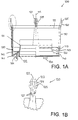
- FIG. 1A shows a side view, partially in cross section, of a windshield assembly 100 which comprises a first, substantially annular windshield 110.
- the first windshield ring 110 has a substantially circular-cylindrical contour.
- a centre axis of the windshield ring 110 is indicated by 111.
- the windshield ring 110 has a top edge 112 and a bottom edge 113.
- a number of coupling arms 120 extend upwards from the top edge 112, for coupling to a protective cap 200 which is to be discussed in more detail. The number of these coupling arms is not critical, and in the example shown is four.
- the coupling arms 120 are distributed at regular intervals along the circumference of the windshield ring 110.
- each coupling arm 120 for this purpose comprises, at its free top end, two substantially axially oriented coupling fingers 121, which are defined by a gap 122 which extends downwards from the free top end of the coupling arm 120, each coupling finger 121 being designed in the shape of an arrow at its end, with an inclined run-in surface 123 and a hook 124 and, at a short axial distance therefrom, a support platform 125.
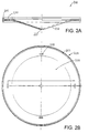
- FIG 2A shows a side view, partially in cross section, of a protective cap 200 which is suitable for mounting on the windshield assembly 100.
- the protective cap 200 is designed in general as a flat, round disc with a circumferential edge 201 which in the example shown is thickened.
- coupling holes 210 are arranged at regular intervals around the centre of the protective cap 200, as can also be seen clearly from the plan view of figure 2B.
- Each coupling hole 210 is substantially rectangular.
- the positions of the coupling holes 210 correspond to the positions of the coupling arms 120 of the windshield ring 110 of system 100, and the dimensions of the coupling holes 210 correspond to the dimensions of the said coupling arms 120, more particularly the dimensions of the coupling fingers 121, as will be clear to a person skilled in the art.
- the protective cap 200 It is particularly easy to arrange the protective cap 200 on the windshield assembly 100.
- the edges of the coupling holes 210 press onto the inclined run-in surfaces 123 of the coupling fingers 121, with the result that the coupling fingers 121 are pressed towards one another and can penetrate into the coupling holes 210.
- This movement ends when the edges of the coupling holes 210 reach the support platforms 125 of the coupling arms 120. Further movement is then prevented. Since the axial distance (i.e.
- the vertical distance in the figure) between the hooks 124 and the corresponding support platform 125 of each coupling arm 120 corresponds to the thickness of the protective cap 200, in this situation the coupling fingers 121 can move apart again, with the result that the hook sections 124 of the coupling fingers 121 engage behind the upperside of the edges of the coupling holes 210.
- the protective cap 200 can then no longer be removed from the windshield assembly 100 except by manually pinching the coupling fingers 121 towards each other.
- the support platforms 125 of the coupling arms 120 are situated at an axial distance from the top edge 112 of the windshield ring 110, which axial distance also defines the axial distance between the protective cap 200 and the windshield ring 110. This distance has been selected in order to define between the windshield ring 110 and the protective cap 200 a suitable passage opening 2 for flue gases.
- the size of this passage opening, and therefore the said vertical distance between the top edge 112 of the windshield ring 110 and the support platforms 125 of the coupling arms 120, is not in itself critical and can be selected by the person skilled in the art according to his own opinion, taking into account applicable approval specifications.
- the coupling holes 210 in the protective cap 200 are of substantially rectangular contour, and their longitudinal dimension oriented substantially tangentially, corresponding to an embodiment of the coupling arms 120 in which the coupling fingers 121 are arranged tangentially next to one another.
- the coupling fingers 121 of the coupling arms 120 may also be arranged next to one another in the radial direction, in which case the longitudinal dimension of the coupling holes 210 will also be radially oriented.
- the dimension of the coupling fingers 121 is such that the coupling holes 210 in the protective cap 200 have a square contour. Obviously, other suitable contours are also possible.
- the protective cap 200 is designed in general as a disc-shaped body which, at least at a central section 220, is shaped in such a manner that the disc-like protective cap 200 is concave on one side and convex on the other side. More particularly, the central section 220 of the disc-like protective cap 200 is of substantially conical design, the vertex 221 of the said conical central part 220 being located substantially centrally.
- the protective cap 200 can be attached to the windshield assembly 100 in two orientations, namely a first mounting orientation in which the vertex 221 of the conical central part 220 is directed upwards, and therefore the convex side of the protective cap 200 faces upwards, and a second mounting orientation, in which the vertex 221 of the conical central part 220 is directed downwards and therefore the concave side faces upwards.
- a first mounting orientation in which the vertex 221 of the conical central part 220 is directed upwards, and therefore the convex side of the protective cap 200 faces upwards
- a second mounting orientation in which the vertex 221 of the conical central part 220 is directed downwards and therefore the concave side faces upwards.
- the coupling fingers 121 of the coupling arms 120 of the windshield assembly 100 fit into the coupling holes 210 in the protective cap 200, and the protective cap can thus be fixed to the windshield assembly 100 by means of a click-fit connection.
- Figure 4A shows a side view, partially in cross section, of an assembled flue-gas discharge system 1, in which the protective cap 200 is mounted on the windshield assembly 100 in the first possible mounting orientation
- figure 4B shows a similar side view, with the protective cap 200 mounted in the second possible mounting orientation.
- the first possible mounting orientation as illustrated in figure 4A is intended for application with gas boilers of the improved-efficiency type
- the second mounting orientation as illustrated in figure 4B is intended for application in gas boilers of the high-efficiency type.
- moisture on the top surface of the protective cap 200 such as rain or condensation, will collect along the outer edge of the protective cap 200, while in the high-efficiency mounting version of figure 4B, such moisture will collect in the centre of the concave top surface of the protective cap. Furthermore, in the improved-efficiency mounting version of figure 4A, moisture on the bottom surface of the protective cap 200 will collect along the circumferential edge 201 of the protective cap 200 and will ultimately drip down off it, while in the high-efficiency mounting version of figure 4B, such moisture will collect at the vertex 221 of the central section 220 and will ultimately drop down off it.
- the protective cap when used in high-efficiency gas boilers, the protective cap may if desired be omitted, since protection against direct ingression of rain is then not necessary per se.
- the flue-gas discharge system 1 has a substantially cylindrical first gas-guiding collar 130, which forms part of the windshield assembly 100 and, in the position in which it has been fitted on a flue-gas outlet pipe, extends substantially in line with such outlet pipe, while the top edge 131 of this cylindrical first gas-guiding collar 130 defines the outlet end of the flue-gas discharge duct.
- the bottom edge 113 of the windshield ring 110 is situated at a lower axial level than the free top edge 131 of this cylindrical first gas-guiding collar 130.
- a first substantially annular moisture-discharge flange 140 is mounted which, as seen from the inside outwards in the radial direction, is directed downwards, i.e. its outer edge 141 is situated at an axially lower level than its inner edge 142.
- the first moisture-discharge flange 140 is attached to the bottom edge 113 of the windshield ring 110 by means of substantially axially oriented coupling limbs 150. In this way, a moisture-discharge opening 143 is defined between the bottom edge 113 of the windshield ring 110 and the outer edge 141 of the moisture-discharge collar 140.
- first gas-guiding collar 130, the first moisture-discharge flange 140 and the windshield ring 110 may in principle be designed as separate components which are subsequently fitted together, these components are preferably, and as shown, produced as an integral unit.
- the coupling limbs 150 between the windshield ring 110 and the first moisture-discharge flange 140 are substantially aligned with the coupling arms 120 between the windshield ring 110 and the protective cap 200.
- the coupling arms 120 and the coupling limbs 150 aligned therewith may, for the sake of sturdy and stable mounting, be designed as a single, continuous coupling bar of a thickness which is greater than the thickness of the windshield ring 110.
- a flue-gas discharge system 1 is provided on its bottom side with a protective skirt 400 which will extend over a gas inlet, not shown for the sake of simplicity. Moisture which reaches the outer surface of this protective skirt 400, for example rainwater, will drip downwards along the said outer surface and will thus reach the roof covering.
- the flue-gas discharge system is therefore provided, beneath the first gas-guiding collar 130, with an annular collection element of a design which is such that moisture from the inner surface of the first gas-guiding collar 130 is collected and discharged radially outwards.
- the flue-gas discharge system is provided, beneath the first moisture-discharge flange, with an annular collection element of a design which is such that moisture which drops downwards from the outer edge of the moisture-discharge flange is collected and is discharged towards the interior of the system, towards the interior of the outlet pipe.
- annular collection element 300 is provided, with a design which is such that it can be mounted in two possible orientations between the windshield assembly 100 and the skirt 400, this collection element 300, in a first mounting orientation as shown in figure 4A, satisfying the requirements imposed for use in improved-efficiency boilers, i.e. that moisture be discharged from the inside outwards, and in the second mounting orientation as shown in figure 4B satisfying the requirements imposed for use in high-efficiency boilers, i.e. that moisture be discharged from the outside inwards.
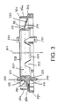
- FIG. 3 An embodiment of this annular collection element 300 will now be discussed in more detail with reference to Figure 3.
- the annular collection element 300 has in general a circular contour, and comprises a second annular moisture-discharge flange 310 with an inner edge 311 and an outer edge 312, which flange 310 has an oblique orientation with respect to the centre axis 301, as can be seen clearly from the cross section of figure 3.
- this second moisture-discharge flange 310 is not critical, it is advantageous if this flange 310 is flat, therefore being shaped according to part of a conical surface.
- the second moisture-discharge flange 310 is provided with a second substantially cylindrical gas-guiding collar 320, the diameter of which substantially corresponds to that of the first cylindrical gas-guiding collar 130 of the windshield assembly 100.
- the second gas-guiding collar 320 has a first axial edge 323 and a second axial edge 324.
- the annular collection element 300 is shown in an orientation in which the inner edge 311 of the second moisture-discharge flange 310 is situated at an axially higher level than the outer edge 312 of the second moisture-discharge flange 310.
- the top surface of the moisture-discharge flange 310 will be referred to hereinafter by the term first surface 313 while the bottom surface of the second moisture-discharge flange 310 in this orientation will be referred to hereinafter by the term second surface 314.
- the annular collection element 300 is provided with substantially axially oriented first coupling members 330, which are able to interact with corresponding second coupling members 160 of the windshield assembly 100.
- first coupling members 330 any suitable coupling members can be used for this purpose, but preferably these coupling members are suitable for producing a click-fit connection, such as the preferred embodiment which is to be discussed below by way of example.
- the first coupling members 330 of the annular collection element 300 are positioned at a radial distance with respect to the second gas-guiding collar 320, so that there is a radial space 321 for accommodating the free end of a gas outlet pipe (not shown) between the said second gas-guiding collar 320 and the first coupling members 330.
- the first coupling members 330 extend in the axial direction from the first surface 313 of the second moisture-discharge flange 310.
- the first coupling members 330 are arranged at regular angular intervals. The number of these coupling members 330 is not critical and may, for example, as in the example illustrated, be three.
- the positions of the corresponding second coupling members 160 of the windshield assembly 100 are adapted accordingly, as will be clear to a person skilled in the art.
- the radial distance between the centre axis 111 and the second coupling members 160 of the windshield assembly 100 is greater than the radial distance between the centre axis 301 and the first coupling members 330 of the annular receiving element 300, in such a manner that during assembly the first coupling members 330 bear against these second coupling members 160, the first coupling members 330 being situated inside the second coupling members 160, as seen in the radial direction.
- the second coupling members of the windshield assembly 100 are provided with a click-fit opening 161 for receiving a barb 331 which is formed on the outer surface of the first coupling members 330.
- the precise contour of such a barb is not critical, as will be clear to a person skilled in the art.
- Axially oriented coupling members are also arranged on the second surface 314 of the second moisture-discharge flange 310, which members will be referred to hereinafter by the term third coupling members 340.
- the third coupling members 340 preferably have a design identical to the design of the first coupling members 330, although this is not essential.
- the third coupling members 340 are provided with a barb 341, similar to the barb 331 of the first coupling members 330, and that there is a radial space 322 for receiving the free end of a gas outlet pipe (not shown) between the second gas-guiding collar 320 and the third coupling members 340.
- the first coupling members 330 and the third coupling members 340 are aligned with one another, but this too is not essential.
- the diameter of the outer edge 312 of the second water-discharge flange 310 is greater than the diameter of the outer edge 141 of the first water-discharge flange 140 of the windshield assembly 100. Furthermore, the diameter of the outer edge 312 of the second water-discharge flange 310 is greater than that of the top end of the said protective skirt 400.
- the first gas-guiding collar 130 has a bottom edge 132, the diameter of which is slightly greater than the diameter of the second gas-guiding collar 320.
- the dimensions of the various components are such that, when the annular element 300 is clicked securely beneath the windshield assembly 100 in the improved-efficiency orientation (figure 4A), i.e. with the first axial edge 323 of the second gas-guiding collar 320 directed upwards, the outermost bottom edge 132 of the first gas-guiding collar 130 is situated at a slightly lower level than the outermost top edge 323 of the second gas-guiding collar 320.
- a first annular gap 351 is defined between the bottom edge 132 of the first gas-guiding collar 130 of the windshield assembly 100 and the top edge 323 of the second gas-guiding collar 320 of the annular element 300.
- Moisture which drips downwards along the inner surface of the first gas-guiding collar 130 falls off the bottom edge 132 of the first gas-guiding collar 130 outside the second gas-guiding collar 320 and passes onto the first surface 313, which runs obliquely downwards towards the outside, of the second water-discharge flange 310, with the result that this moisture is also discharged radially outwards and falls downwards off the outer edge 312 of the second moisture-discharge flange 310, onto the outer surface of the said skirt 400.
- a second, substantially cylindrical windshield ring 360 is preferably, and as shown, positioned on the first surface 313 of the second water-discharge flange 310, the vertical or axial dimension of which second windshield ring 360 is such that the free top edge 361 of this second windshield ring 360 is situated at substantially the same axial position as the outer edge 141 of the first water-discharge flange 140.
- the second windshield ring 360 is substantially axially oriented, although this is not necessary.
- said second windshield ring 360 is provided at its bottom with at least one, and preferably a plurality of passage openings 362.
- such passage openings 362 are aligned in the tangential direction with the said first and second coupling members 330, 160, so that those coupling members 330, 160 also function as a windbreak for wind which nevertheless blows inwards via said passage holes 362.
- the vertical or axial dimension of the second windshield ring 360 is such that the free top edge 361 thereof adjoins the outer edge 141 of the first water-discharge flange 140 or the bottom surface of the first water-discharge flange 140. In such a case, moisture which flows downwards on the first water-discharge flange 140 would drip downwards along the outer wall of the second windshield ring 360. It is therefore not essential that the second windshield ring 360 has a greater diameter than the diameter of the outer circumference of the first water-discharge flange 140.
- annular element 300 may also, by means of the third coupling members 340, be clicked securely in an inverted position onto the windshield assembly 100, in which case it functions to discharge moisture to the interior of the flue-gas discharge system 1, towards the interior of a gas outlet pipe.
- the second water-discharge flange 310 is provided with a third windshield ring 370 which extends axially from the second surface 314 of the second water-discharge flange 310, i.e. vertically upwards in the high-efficiency orientation shown in figure 4B.
- the third windshield ring 370 adjoins the outer edge 312 of the second water-discharge flange 310.
- the third windshield ring 370 is substantially axially oriented, but this is not necessary.
- the free edge 371 of the third windshield ring 370 is situated radially outside the circumferential edge 141 of the first water-discharge flange 140 and may be situated at virtually the same vertical level or higher, when viewed in the axial direction. Moisture which drips downwards from the outer edge 141 of the first water-discharge flange 140 then reaches the second surface 314 of the second water-discharge flange 310, the inclination of which is such that this moisture is conveyed inwards, towards the inner edge 311 of the second water-discharge flange 310 and thus towards the second gas-guiding collar 320. Moisture which drips downwards along the inner surface of the first gas-guiding collar 130 and falls down off the bottom edge 132 of this first gas-guiding collar 130 will likewise reach the second surface 314 of the second water-discharge flange 310.
- the first axial end edge of the second gas-guiding collar 320 is directed downwards, and the second axial end edge 324 is directed upwards.
- the second gas-guiding collar 320 is provided with a few passage openings 325, in the example shown in the form of V-shaped cutouts. Said openings 325 are situated in that part of the second gas-guiding collar 320 which extends between the second axial end edge 324 and the inner edge 311 of the second water-discharge flange 310, and preferably adjoin the second surface 314 of the second water-discharge flange 310.
- the number of these passage openings 325 is not critical, and in the example shown is six.
- the third coupling members 340 are designed to create a connection between the annular element 300 and the protective skirt 400 in the first mounting orientation (improved-efficiency; figure 4A), and the first coupling members 330 are designed to create a connection between the annular element 300 and the protective skirt 400 in the second mounting orientation (high-efficiency; figure 4B).
- Figures 4A and 4B illustrate that the protective skirt 400 is provided with a support ring 403 which is directed inwards from the top edge 402 and has an inner edge 404, the diameter of which corresponds to the outer surface of the first and third coupling members 330, 340 of the annular element 300.
- the barbs 341 of the third coupling members 340 engage beneath this inner edge 404, in order thus to create a click-fit connection.
- the annular element 300 is provided, on its second surface 314, with first support ribs 380 which rest on the top surface of the support ring 403 of the protective skirt 400.
- the barbs 331 of the first coupling members 330 engage beneath this inner edge 404, in order thus to create a click-fit connection.
- the annular element 300 is provided, on its first surface 313, with second support ribs 390 which rest on the top surface of the support ring 403 of the protective skirt 400.
- the present invention provides a flue-gas discharge system 1 which comprises three components, namely the windshield assembly 100, the annular element 300 and the protective cap 200.
- the annular element 300 can be attached in two axial orientations to the underside of the windshield assembly 100, preferably in each case by means of a click-fit connection.
- the annular element 300 makes the flue-gas discharge system suitable for improved-efficiency specifications, since moisture is discharged from the interior of the flue-gas discharge system towards the outside.
- the annular element 300 makes the flue-gas discharge system suitable for high-efficiency specifications, since moisture is discharged from the outside of the flue-gas discharge system towards the interior.
- the protective cap 200 can likewise be attached to the top side of the windshield assembly 100 in two axial orientations, likewise preferably by means of a click-fit connection. In a first mounting orientation, the protective cap 200 is concave on its underside, so that the protective cap allows the flue-gas discharge system to satisfy improved-efficiency specifications, while in the second mounting orientation the protective cap is convex on its underside and allows the flue-gas discharge system to satisfy high-efficiency specifications.
Landscapes
- Engineering & Computer Science (AREA)
- Chemical & Material Sciences (AREA)
- Combustion & Propulsion (AREA)
- Mechanical Engineering (AREA)
- General Engineering & Computer Science (AREA)
- Chimneys And Flues (AREA)
- Filtering Of Dispersed Particles In Gases (AREA)
Applications Claiming Priority (2)
| Application Number | Priority Date | Filing Date | Title |
|---|---|---|---|
| NL1014235A NL1014235C2 (nl) | 2000-01-31 | 2000-01-31 | Rookgasafvoerstelsel. |
| NL1014235 | 2000-01-31 |
Publications (1)
| Publication Number | Publication Date |
|---|---|
| EP1122496A1 true EP1122496A1 (de) | 2001-08-08 |
Family
ID=19770705
Family Applications (1)
| Application Number | Title | Priority Date | Filing Date |
|---|---|---|---|
| EP01200320A Withdrawn EP1122496A1 (de) | 2000-01-31 | 2001-01-29 | Abgasabführung |
Country Status (2)
| Country | Link |
|---|---|
| EP (1) | EP1122496A1 (de) |
| NL (1) | NL1014235C2 (de) |
Cited By (3)
| Publication number | Priority date | Publication date | Assignee | Title |
|---|---|---|---|---|
| EP1243856A1 (de) * | 2001-03-20 | 2002-09-25 | InterActive bouwprodukten B.V. | Rauchgasabzug mit Kupplungsring |
| WO2005083324A1 (en) * | 2004-03-01 | 2005-09-09 | Ivo Vesely | Cowl for reduction of chimney effect |
| CN115095879A (zh) * | 2022-07-25 | 2022-09-23 | 珠海格力电器股份有限公司 | 烟管组件和家用电器 |
Citations (3)
| Publication number | Priority date | Publication date | Assignee | Title |
|---|---|---|---|---|
| EP0801266A2 (de) * | 1996-04-10 | 1997-10-15 | InterActive Holding B.V. | Aufsatz für ein Abgasrohr einer Heizungsanlage |
| NL1005472C2 (nl) * | 1997-03-07 | 1998-09-18 | Muelink & Grol Bv | Uitstroommondstuk voor rookgasafvoer van een verbrandingshaard. |
| WO2000077454A1 (en) * | 1999-06-16 | 2000-12-21 | Interactive Bouwprodukten B.V. | Shielding device |
-
2000
- 2000-01-31 NL NL1014235A patent/NL1014235C2/nl not_active IP Right Cessation
-
2001
- 2001-01-29 EP EP01200320A patent/EP1122496A1/de not_active Withdrawn
Patent Citations (3)
| Publication number | Priority date | Publication date | Assignee | Title |
|---|---|---|---|---|
| EP0801266A2 (de) * | 1996-04-10 | 1997-10-15 | InterActive Holding B.V. | Aufsatz für ein Abgasrohr einer Heizungsanlage |
| NL1005472C2 (nl) * | 1997-03-07 | 1998-09-18 | Muelink & Grol Bv | Uitstroommondstuk voor rookgasafvoer van een verbrandingshaard. |
| WO2000077454A1 (en) * | 1999-06-16 | 2000-12-21 | Interactive Bouwprodukten B.V. | Shielding device |
Cited By (3)
| Publication number | Priority date | Publication date | Assignee | Title |
|---|---|---|---|---|
| EP1243856A1 (de) * | 2001-03-20 | 2002-09-25 | InterActive bouwprodukten B.V. | Rauchgasabzug mit Kupplungsring |
| WO2005083324A1 (en) * | 2004-03-01 | 2005-09-09 | Ivo Vesely | Cowl for reduction of chimney effect |
| CN115095879A (zh) * | 2022-07-25 | 2022-09-23 | 珠海格力电器股份有限公司 | 烟管组件和家用电器 |
Also Published As
| Publication number | Publication date |
|---|---|
| NL1014235C2 (nl) | 2001-08-01 |
Similar Documents
| Publication | Publication Date | Title |
|---|---|---|
| US8298053B2 (en) | Omnidirectional vent cap | |
| CN103562512B (zh) | 排气烟囱管道罩盖 | |
| US3650198A (en) | Dome type vent top | |
| EP1122496A1 (de) | Abgasabführung | |
| US8246430B1 (en) | Chimney cap | |
| US4638727A (en) | Chimney cowls | |
| US20040182763A1 (en) | Rainwater surface drain | |
| US20030178349A1 (en) | Down pipe filter | |
| AU719283B2 (en) | Static venting system | |
| US4206693A (en) | Chimney cowls | |
| JP2000084352A (ja) | 煙突一体型排煙脱硫装置 | |
| EP0809074B1 (de) | Eisbildungsfreier Abfuhraufbau | |
| US4249920A (en) | Scrubber and method utilizing wetted slotted screens for removing flyash from flue gas | |
| CN217662152U (zh) | 一种烟囱雨分离器 | |
| EP0182534B1 (de) | Schornsteinaufsatz | |
| EP0753703A2 (de) | Schornsteinkopf | |
| EP1108188B1 (de) | Schutzvorrichtung | |
| NL1013646C2 (nl) | Beschermkorf voor een muurdoorvoersysteem. | |
| US2427413A (en) | Chimney hood | |
| EP0679841B1 (de) | Anordnung eines Luftzufuhrrohres und/oder eines Rauchgas-Abfuhrrohres für die Verbindung zu einem Ofen | |
| CN216855966U (zh) | 管束除雾器的导流结构 | |
| CN208435483U (zh) | 用于吸尘器的尘杯和吸尘器 | |
| SE515183C2 (sv) | Takventilationsdon | |
| CN215027523U (zh) | 一种新型动态可调双挡板直排脱水器 | |
| CN209934456U (zh) | 一种烟囱冷凝水收集装置 |
Legal Events
| Date | Code | Title | Description |
|---|---|---|---|
| PUAI | Public reference made under article 153(3) epc to a published international application that has entered the european phase |
Free format text: ORIGINAL CODE: 0009012 |
|
| AK | Designated contracting states |
Kind code of ref document: A1 Designated state(s): DE FR GB IT NL |
|
| AX | Request for extension of the european patent |
Free format text: AL;LT;LV;MK;RO;SI |
|
| 17P | Request for examination filed |
Effective date: 20020114 |
|
| AKX | Designation fees paid |
Free format text: DE FR GB IT NL |
|
| GRAP | Despatch of communication of intention to grant a patent |
Free format text: ORIGINAL CODE: EPIDOSNIGR1 |
|
| STAA | Information on the status of an ep patent application or granted ep patent |
Free format text: STATUS: THE APPLICATION IS DEEMED TO BE WITHDRAWN |
|
| 18D | Application deemed to be withdrawn |
Effective date: 20050330 |