EP1122508A2 - Vorrichtung zur Identifikation von Schützen - Google Patents
Vorrichtung zur Identifikation von Schützen Download PDFInfo
- Publication number
- EP1122508A2 EP1122508A2 EP00125455A EP00125455A EP1122508A2 EP 1122508 A2 EP1122508 A2 EP 1122508A2 EP 00125455 A EP00125455 A EP 00125455A EP 00125455 A EP00125455 A EP 00125455A EP 1122508 A2 EP1122508 A2 EP 1122508A2
- Authority
- EP
- European Patent Office
- Prior art keywords
- detection unit
- evaluation
- shot
- shooting range
- shooter
- Prior art date
- Legal status (The legal status is an assumption and is not a legal conclusion. Google has not performed a legal analysis and makes no representation as to the accuracy of the status listed.)
- Granted
Links
- 238000001514 detection method Methods 0.000 claims description 47
- 238000011156 evaluation Methods 0.000 claims description 29
- 230000005855 radiation Effects 0.000 claims description 13
- 238000010304 firing Methods 0.000 abstract description 6
- 239000007789 gas Substances 0.000 description 7
- 238000005259 measurement Methods 0.000 description 5
- 238000010586 diagram Methods 0.000 description 2
- 238000000034 method Methods 0.000 description 2
- 230000005540 biological transmission Effects 0.000 description 1
- 238000002592 echocardiography Methods 0.000 description 1
- 230000004807 localization Effects 0.000 description 1
- 238000012545 processing Methods 0.000 description 1
- 230000002123 temporal effect Effects 0.000 description 1
- 230000001960 triggered effect Effects 0.000 description 1
Images

Classifications
-
- F—MECHANICAL ENGINEERING; LIGHTING; HEATING; WEAPONS; BLASTING
- F41—WEAPONS
- F41J—TARGETS; TARGET RANGES; BULLET CATCHERS
- F41J11/00—Target ranges
Definitions
- the invention relates to a device for identifying shooters according to the preamble of claim 1.
- At shooting ranges marked by several shooting lanes their each is equipped with an automatic hit detection system and which in temporal connection between multiple shooters is common the problem, the hit situation signaled by a hit detection system a shot to a specific shooter or weapon assign.
- This is the case, for example, with parallel shooting lanes not to rule out that one, signaled by a hit detection system Hit position comes from a shooter who is just this shooting range not currently used, so there is a misregistration of such a hit is coming.
- the one used in the device Detection unit for detecting infrared radiation is set up. Every shot is known for the sudden release of hot gases characterized, and according to the invention this occurrence of hot gases determined by a corresponding sensor arrangement of the detection unit and represented by a corresponding electrical signal.
- everybody Shot is associated with a single expulsion of hot gas, so that based on a temperature pattern related to gas ejection - seen over time - the triggering of a shot can be ascertained perfectly is.
- the detection unit responds to infrared radiation Sensors, for example photodiodes used, their extraordinary high cut-off frequency even a detection of high closing speeds enables, without the problem of misinterpretation of the received measurement signals.
- the detection unit is for this purpose at a defined distance from the shooter's usual location a firing lane, basically each of the several Such a detection unit is assigned to shooting lanes of the shooting range which is thus set up to generate such a signal which indicates that from the point of the Protect a shot has been fired.
- a radar can also be used as a detection unit. This is with the proviso arranged and set up so that a floor is recorded in any case, which is fired by a shooter using the respective shooting range has been.
- a monostatic radar is preferably used, which receiver and transmitter are combined in one unit are, which can be arranged to the side or above the shooting range.
- bistatic radar devices in which transmitters and Receivers are spatially separated from each other. As part of the any radar method can be used, their signal evaluation on transit time measurements, frequency shifts of Frequencies of transmission and reception signals etc. based. In particular can do anything, based on a continuous or pulsed radiation Radar methods are used.
- a Doppler radar is preferred for use.
- the detection unit is designed that their reception characteristics to the location of the Protecting a particular shooting range is limited. For example by one that precedes the radiation-sensitive sensors Focusing lens system can be achieved through which as a result, reception of infrared radiation from neighboring shooting ranges is suppressed.
- the radar device used as the detection unit corresponds to the features of claim 4 also arranged and furnished with the proviso that its directional characteristic to the area of each to be monitored Shooting range is limited.
- the radar device is such created that floor movements of neighboring shooting lanes are not recorded become.
- the triggering of a shot is with the sudden local appearance hot gas, but especially when used intensively as well as the run of the respective one at high shot sequence speeds Gun warms up and thus becomes a source of infrared radiation.
- Detection unit own discriminator circuit which is set up accordingly is that of those received via the radiation sensitive sensors
- Such signals are separable, which is formed by the hot gas is, so that other received infrared signals are not correct as a trigger of a shot are interpretable.
- claims 6 to 8 are based on the further embodiment of the Device directed as far as the evaluation of the detection unit determined signal goes.
- an evaluation unit is provided that with the detection unit on the one hand and an automatic hit detection system on the other hand, which is related to the latter records transfers to the evaluation unit, each denoting hit locations, namely Hit locations with regard to the target assigned to the respective shooting range.
- the detection unit ensures that only those data are correct interpreted as the hit positions of the shooter using this shooting range so that other hit data are ignored.
- the filter function described above can be implemented in such detection units whose principle is based on the evaluation of infrared radiation, but also for those that are designed as radar. Especially in the latter Trap, another filter function can be implemented in that the speed of the floor is detected, by defining Limits of the speed measurement data of such projectiles are hidden can be whose speed data does not match that of the current corresponds to the projectile used.
- a system is thus available in the device according to the invention, which in a simple and reproducible way, a clear assignment of hits to the shooter who has the respective shooting range several shooting lanes equipped shooting range.
- Measurement processing speed which is favored by the fact that ultimately an electromagnetic and none for shooter identification Sound wave is used.
- the result is much more reliable Rifle identification.
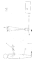
- FIG. 1 denotes a detection unit, which is located in front of one at the bottom Protect 2 and place it on the output side with an evaluation unit 3 communicates.
- the evaluation unit 3 also has a drawing non-reproduced hit detection device in connection, the related is set up that according to the respective hit situation preferably an electrical signal is generated and the evaluation unit 3 is transmitted.
- the detection unit 1 is intended and set up for the purpose of firing to determine a weapon 4 developed infrared radiation and this finding represented by an electrical signal.
- the opening angle 6 in connection with the distance 7 of the detection unit 1 from the shooter 2 is designed so that the detection range is one of several, for example parallel, shooting lanes limited is.
- the detection unit 1 receives through the input lens system 5 thus a spatially limited reception characteristic, through which the Evaluation of such infrared radiation from the firing of a weapon an immediately adjacent shooting range, is excluded.
- the Detection unit 1 is thus at a defined distance from the Protect and in such an orientation with respect to the longitudinal axis of the Shooting range that the above limitation of the recorded Infrared radiation is given.
- the evaluation unit 3 is now set up in such a way that a a record describing a hit situation only for evaluation or registration arrives when it has been determined via the detection unit 1 is that the shot associated with the record is actually from the weapon 4 of shooter 2, who used the current shooting range. He goes no such signal from the detection unit 1, the one hit position descriptive record ignored.
- the exemplary embodiment shown in FIG. 2 essentially corresponds to that 1, with corresponding functional elements also corresponding are numbered, so that a related description is repeated can be dispensed with.
- the detection unit 8 now by a radar device here a monostatic Radar is formed, in particular a Doppler radar
- the directional characteristic runs vertically. Its directional characteristic, especially its The main lobe is designed in such a way that the swept angle 9 is approximately the same Corresponds to the width of the shooting range to be monitored. Instead of a vertical one Orientation is also considered here, at an angle from the shooter 2 runs away.
- the evaluation of the gained, at least the presence of a storey signal is the same as for the Embodiment according to FIG. 1.
- the projectile radar measurement however, also includes the acquisition of trajectory data as well as the speed, which is a further refined evaluation enable.
- the further evaluation of the information obtained using radar or data takes place in a similar manner as in the exemplary embodiment 1.
Landscapes
- Engineering & Computer Science (AREA)
- General Engineering & Computer Science (AREA)
- Aiming, Guidance, Guns With A Light Source, Armor, Camouflage, And Targets (AREA)
- Radar Systems Or Details Thereof (AREA)
- Optical Radar Systems And Details Thereof (AREA)
- Radiation Pyrometers (AREA)
- Geophysics And Detection Of Objects (AREA)
Abstract
Description
Claims (8)
- Vorrichtung zur Identifikation von Schützen (2) zur Verwendung auf einem durch mehrere Bahnen gekennzeichneten Schießstand mit einer Detektionseinheit (1) zur Identifizierung des Schützen (2), dadurch gekennzeichnet, dass die Detektionseinheit (1) zur Erfassung der durch einen Schuss emittierten Infrarotstrahlung eingerichtet ist.
- Vorrichtung zur Identifikation von Schützen (2) zur Verwendung auf einem durch mehrere Bahnen gekennzeichneten Schießstand mit einer Detektionseinheit (8) zur Identifizierung des Schützen (2), durch gekennzeichnet, dass die Detektionseinheit (8) ein Radargerät ist.
- Vorrichtung nach Anspruch 1, dadurch gekennzeichnet, dass die Empfangscharakteristik der Detektionseinheit (1) auf den räumlichen Bereich des Standorts des Schützen der jeweiligen Schießbahn beschränkt ist.
- Vorrichtung nach Anspruch 2, dadurch gekennzeichnetdass die Sende- und Empfangscharakteristik der Detektionseinheit (8) auf den räumlichen Bereich der jeweiligen Schießbahn beschränkt ist.
- Vorrichtung nach Anspruch 1 oder 3, dadurch gekennzeichnet, dass die Detektionseinheit (1) mit einer Diskriminatorschaltung zur Erkennung solcher Infrarotsignale eingerichtet ist, die auf die mit einem Schuss verbundenen Gastemperaturen abgestimmt ist.
- Vorrichtung nach einem der vorangegangenen Ansprüche 1 bis 5, gekennzeichnet durch eine Auswerteinheit (3), die mit der Detektionseinheit (1,8) einerseits und mit einem Treffererkennungssystem andererseits in Verbindung steht.
- Vorrichtung nach Anspruch 6, dadurch gekennzeichnet, dass die Auswerteinheit (3) dahingehend eingerichtet ist, dass lediglich solche Trefferlagen beschreibende Datensätze registriert und einer Auswertung zugänglich gemacht werden, die auf mittels der Detektionseinheit (1,8) erkannte Schüsse und damit einen bestimmten Schützen (2) zurückführbar sind.
- Vorrichtung nach einem der vorangegangenen Ansprüche 1 bis 7, dadurch gekennzeichnet, dass die Auswerteinheit (3) zusätzlich zur Auswertung der Laufzeit eines Geschosses eingerichtet ist.
Applications Claiming Priority (2)
| Application Number | Priority Date | Filing Date | Title |
|---|---|---|---|
| DE20001720U DE20001720U1 (de) | 2000-02-01 | 2000-02-01 | Vorrichtung zur Identifikation von Schützen |
| DE20001720U | 2000-02-01 |
Publications (3)
| Publication Number | Publication Date |
|---|---|
| EP1122508A2 true EP1122508A2 (de) | 2001-08-08 |
| EP1122508A3 EP1122508A3 (de) | 2003-11-05 |
| EP1122508B1 EP1122508B1 (de) | 2005-10-12 |
Family
ID=7936676
Family Applications (1)
| Application Number | Title | Priority Date | Filing Date |
|---|---|---|---|
| EP20000125455 Expired - Lifetime EP1122508B1 (de) | 2000-02-01 | 2000-11-21 | Vorrichtung zur Identifikation von Schützen |
Country Status (2)
| Country | Link |
|---|---|
| EP (1) | EP1122508B1 (de) |
| DE (2) | DE20001720U1 (de) |
Cited By (3)
| Publication number | Priority date | Publication date | Assignee | Title |
|---|---|---|---|---|
| US11436823B1 (en) | 2019-01-21 | 2022-09-06 | Cyan Systems | High resolution fast framing infrared detection system |
| US11448483B1 (en) | 2019-04-29 | 2022-09-20 | Cyan Systems | Projectile tracking and 3D traceback method |
| US11637972B2 (en) | 2019-06-28 | 2023-04-25 | Cyan Systems | Fast framing moving target imaging system and method |
Families Citing this family (2)
| Publication number | Priority date | Publication date | Assignee | Title |
|---|---|---|---|---|
| DE20304597U1 (de) * | 2003-03-22 | 2004-05-06 | Bücheler, Gerd | Anordnung zur Identifikation eines Schützen |
| WO2009122407A1 (en) * | 2008-04-01 | 2009-10-08 | Alon Naim | Automatic mobile land target especially for golf and method of using it |
Family Cites Families (9)
| Publication number | Priority date | Publication date | Assignee | Title |
|---|---|---|---|---|
| US3699341A (en) * | 1968-09-23 | 1972-10-17 | Gen Electric | Muzzle flash detector |
| DE2346588C2 (de) | 1973-09-15 | 1986-06-05 | Allen Stefan Dipl.-Ing. 4000 Düsseldorf Wojcinski | Vorrichtung zur Markierung und Sichtbarmachung von Geschoßeinschlägen |
| GB1522831A (en) | 1975-06-24 | 1978-08-31 | Rfd Systems Eng Ltd | Gunnery training aids having projectors with light beam deflection means |
| US4030097A (en) * | 1976-02-02 | 1977-06-14 | Gedeon Anthony A | Muzzle velocity chronograph |
| DE4411261C2 (de) | 1993-04-03 | 1998-07-02 | Secotron Elektrogeraetebau Gmb | Interaktives Videosystem |
| US5577733A (en) * | 1994-04-08 | 1996-11-26 | Downing; Dennis L. | Targeting system |
| DE4413628A1 (de) | 1994-04-19 | 1995-11-09 | Karl Stefan Riener | Verfahren und Vorrichtung zum Betreiben einer Filmprojectionsvorrichtung, insbesondere in einem Schießkino |
| US5686889A (en) * | 1996-05-20 | 1997-11-11 | The United States Of America As Represented By The Secretary Of The Army | Infrared sniper detection enhancement |
| DE29819394U1 (de) * | 1998-10-30 | 1999-12-02 | Bücheler, Gerd, 70376 Stuttgart | Vorrichtung zur Treffererkennung bei Schießanlagen |
-
2000
- 2000-02-01 DE DE20001720U patent/DE20001720U1/de not_active Expired - Lifetime
- 2000-11-21 EP EP20000125455 patent/EP1122508B1/de not_active Expired - Lifetime
- 2000-11-21 DE DE50011330T patent/DE50011330D1/de not_active Expired - Fee Related
Non-Patent Citations (1)
| Title |
|---|
| None |
Cited By (6)
| Publication number | Priority date | Publication date | Assignee | Title |
|---|---|---|---|---|
| US11436823B1 (en) | 2019-01-21 | 2022-09-06 | Cyan Systems | High resolution fast framing infrared detection system |
| US11810342B2 (en) | 2019-01-21 | 2023-11-07 | Cyan Systems | High resolution fast framing infrared detection system |
| US11448483B1 (en) | 2019-04-29 | 2022-09-20 | Cyan Systems | Projectile tracking and 3D traceback method |
| US11994365B2 (en) | 2019-04-29 | 2024-05-28 | Cyan Systems | Projectile tracking and 3D traceback method |
| US11637972B2 (en) | 2019-06-28 | 2023-04-25 | Cyan Systems | Fast framing moving target imaging system and method |
| US12075185B2 (en) | 2019-06-28 | 2024-08-27 | Cyan Systems | Fast framing moving target imaging system and method |
Also Published As
| Publication number | Publication date |
|---|---|
| DE20001720U1 (de) | 2000-03-30 |
| EP1122508B1 (de) | 2005-10-12 |
| EP1122508A3 (de) | 2003-11-05 |
| DE50011330D1 (de) | 2005-11-17 |
Similar Documents
| Publication | Publication Date | Title |
|---|---|---|
| DE69526139T2 (de) | Verfahren und System zur Positionsbestimmung einer Schusswaffe mittels einer akustischer Detektion | |
| EP0890818A2 (de) | Schusssimulationsverfahren und Vorrichtung zur Durchführung des Verfahrens | |
| DE102015002737A1 (de) | Verfahren und Vorrichtung zum Bereitstellen eines Scheinzieles zum Schutz eines Fahrzeuges und / oder Objektes vor radargelenkten Suchköpfen | |
| EP1122508B1 (de) | Vorrichtung zur Identifikation von Schützen | |
| DE3028545C2 (de) | Verfahren zur Schußsimulation bei beweglichen Zielen mittels Lichtsignalen | |
| EP3348953B1 (de) | Vorrichtung zum ermitteln der treffsicherheit eines schützen | |
| EP0152516B1 (de) | Mine | |
| DE2922592C2 (de) | Verfahren zur Abwehr von Flugkörpern | |
| DE3317925C2 (de) | Detektionsanordnung zur Detektion ankommender Objekte | |
| CH694668A5 (de) | Identifikations- und Simulationssystem und Verfahren zur Simulation eines Schusses. | |
| EP0154809A1 (de) | Verfahren zur Gefechtssimulation | |
| DE3927662C2 (de) | ||
| DE60219564T2 (de) | Verfahren zum Einstellen eines Geschosszünders, Programmiereinrichtung und Zeitzünder die in einen solchem Verfahren verwendet werden | |
| EP1159578B1 (de) | Verfahren zur schusssimulation | |
| DE102009011447B4 (de) | Verfahren zum Zünden eines Gefechtskopfs einer Granate und Fahrzeug | |
| EP3260808B1 (de) | Verfahren zur ablagekorrekture eines waffensystems | |
| EP3034983B2 (de) | Maschinenwaffe | |
| EP2840414B1 (de) | Verfahren zum Schützen eines Schutzobjekts | |
| DE3404402C1 (de) | Einrichtung zur optischen winkelmäßigen Erkennung eines beweglichen Zieles | |
| DE3843601C2 (de) | ||
| DE102019105769B4 (de) | Geschoss | |
| DE69408079T2 (de) | System zur Lokalisierung von mobilen Objekten | |
| DE29819394U1 (de) | Vorrichtung zur Treffererkennung bei Schießanlagen | |
| DE2734787C1 (de) | Anordnung zum selektiven Abfeuern einer horizontal wirkenden Waffe | |
| EP2600172B1 (de) | Radarvorrichtung |
Legal Events
| Date | Code | Title | Description |
|---|---|---|---|
| PUAI | Public reference made under article 153(3) epc to a published international application that has entered the european phase |
Free format text: ORIGINAL CODE: 0009012 |
|
| AK | Designated contracting states |
Kind code of ref document: A2 Designated state(s): AT BE CH CY DE DK ES FI FR GB GR IE IT LI LU MC NL PT SE TR |
|
| AX | Request for extension of the european patent |
Free format text: AL;LT;LV;MK;RO;SI |
|
| PUAL | Search report despatched |
Free format text: ORIGINAL CODE: 0009013 |
|
| AK | Designated contracting states |
Kind code of ref document: A3 Designated state(s): AT BE CH CY DE DK ES FI FR GB GR IE IT LI LU MC NL PT SE TR |
|
| AX | Request for extension of the european patent |
Extension state: AL LT LV MK RO SI |
|
| 17P | Request for examination filed |
Effective date: 20040127 |
|
| AKX | Designation fees paid |
Designated state(s): CH DE GB LI |
|
| 17Q | First examination report despatched |
Effective date: 20040622 |
|
| GRAP | Despatch of communication of intention to grant a patent |
Free format text: ORIGINAL CODE: EPIDOSNIGR1 |
|
| GRAS | Grant fee paid |
Free format text: ORIGINAL CODE: EPIDOSNIGR3 |
|
| GRAA | (expected) grant |
Free format text: ORIGINAL CODE: 0009210 |
|
| AK | Designated contracting states |
Kind code of ref document: B1 Designated state(s): CH DE GB LI |
|
| PG25 | Lapsed in a contracting state [announced via postgrant information from national office to epo] |
Ref country code: GB Free format text: LAPSE BECAUSE OF FAILURE TO SUBMIT A TRANSLATION OF THE DESCRIPTION OR TO PAY THE FEE WITHIN THE PRESCRIBED TIME-LIMIT Effective date: 20051012 |
|
| REG | Reference to a national code |
Ref country code: GB Ref legal event code: FG4D Free format text: NOT ENGLISH |
|
| REG | Reference to a national code |
Ref country code: CH Ref legal event code: EP |
|
| REG | Reference to a national code |
Ref country code: CH Ref legal event code: NV Representative=s name: A. BRAUN, BRAUN, HERITIER, ESCHMANN AG PATENTANWAE |
|
| REF | Corresponds to: |
Ref document number: 50011330 Country of ref document: DE Date of ref document: 20051117 Kind code of ref document: P |
|
| GBV | Gb: ep patent (uk) treated as always having been void in accordance with gb section 77(7)/1977 [no translation filed] |
Effective date: 20051012 |
|
| PLBE | No opposition filed within time limit |
Free format text: ORIGINAL CODE: 0009261 |
|
| STAA | Information on the status of an ep patent application or granted ep patent |
Free format text: STATUS: NO OPPOSITION FILED WITHIN TIME LIMIT |
|
| 26N | No opposition filed |
Effective date: 20060713 |
|
| PGFP | Annual fee paid to national office [announced via postgrant information from national office to epo] |
Ref country code: CH Payment date: 20061123 Year of fee payment: 7 |
|
| PGFP | Annual fee paid to national office [announced via postgrant information from national office to epo] |
Ref country code: DE Payment date: 20061202 Year of fee payment: 7 |
|
| REG | Reference to a national code |
Ref country code: CH Ref legal event code: PFA Owner name: BUECHELER, GERD Free format text: BUECHELER, GERD#KOELNER STRASSE 18#70376 STUTTGART (DE) $ WOLFGANG SCHNITZLER#GARTENSTRASSE 6#78112 ST. GEORGEN (DE) -TRANSFER TO- BUECHELER, GERD#KOELNER STRASSE 18#70376 STUTTGART (DE) $ WOLFGANG SCHNITZLER#GARTENSTRASSE 6#78112 ST. GEORGEN (DE) |
|
| PG25 | Lapsed in a contracting state [announced via postgrant information from national office to epo] |
Ref country code: LI Free format text: LAPSE BECAUSE OF NON-PAYMENT OF DUE FEES Effective date: 20071130 Ref country code: CH Free format text: LAPSE BECAUSE OF NON-PAYMENT OF DUE FEES Effective date: 20071130 |
|
| REG | Reference to a national code |
Ref country code: CH Ref legal event code: PL |
|
| PG25 | Lapsed in a contracting state [announced via postgrant information from national office to epo] |
Ref country code: DE Free format text: LAPSE BECAUSE OF NON-PAYMENT OF DUE FEES Effective date: 20080603 |