EP1122648A2 - Procedé pour la réalisation et/ou l'utilisation d' un support-chargeur pour un appareil mobile - Google Patents
Procedé pour la réalisation et/ou l'utilisation d' un support-chargeur pour un appareil mobile Download PDFInfo
- Publication number
- EP1122648A2 EP1122648A2 EP01200003A EP01200003A EP1122648A2 EP 1122648 A2 EP1122648 A2 EP 1122648A2 EP 01200003 A EP01200003 A EP 01200003A EP 01200003 A EP01200003 A EP 01200003A EP 1122648 A2 EP1122648 A2 EP 1122648A2
- Authority
- EP
- European Patent Office
- Prior art keywords
- cradle
- computer
- power
- cable
- electronic device
- Prior art date
- Legal status (The legal status is an assumption and is not a legal conclusion. Google has not performed a legal analysis and makes no representation as to the accuracy of the status listed.)
- Withdrawn
Links
Images








Classifications
-
- H—ELECTRICITY
- H02—GENERATION; CONVERSION OR DISTRIBUTION OF ELECTRIC POWER
- H02J—ELECTRIC POWER NETWORKS; CIRCUIT ARRANGEMENTS OR SYSTEMS FOR SUPPLYING OR DISTRIBUTING ELECTRIC POWER; SYSTEMS FOR STORING ELECTRIC ENERGY
- H02J7/00—Circuit arrangements for charging or discharging batteries or for supplying loads from batteries
- H02J7/02—Circuit arrangements for charging or discharging batteries or for supplying loads from batteries for charging batteries from AC mains by converters
-
- G—PHYSICS
- G06—COMPUTING OR CALCULATING; COUNTING
- G06F—ELECTRIC DIGITAL DATA PROCESSING
- G06F1/00—Details not covered by groups G06F3/00 - G06F13/00 and G06F21/00
- G06F1/26—Power supply means, e.g. regulation thereof
- G06F1/266—Arrangements to supply power to external peripherals either directly from the computer or under computer control, e.g. supply of power through the communication port, computer controlled power-strips
-
- H—ELECTRICITY
- H02—GENERATION; CONVERSION OR DISTRIBUTION OF ELECTRIC POWER
- H02J—ELECTRIC POWER NETWORKS; CIRCUIT ARRANGEMENTS OR SYSTEMS FOR SUPPLYING OR DISTRIBUTING ELECTRIC POWER; SYSTEMS FOR STORING ELECTRIC ENERGY
- H02J4/00—Circuit arrangements for mains or distribution networks not specified as AC or DC; Circuit arrangements for mains or distribution networks combining AC and DC sections or sub-networks
- H02J4/20—Networks integrating separated AC and DC power sections
- H02J4/25—Networks integrating separated AC and DC power sections for transfer of electric power between AC and DC networks, e.g. for supplying the DC section within a load from an AC mains system
-
- H—ELECTRICITY
- H04—ELECTRIC COMMUNICATION TECHNIQUE
- H04M—TELEPHONIC COMMUNICATION
- H04M2250/00—Details of telephonic subscriber devices
- H04M2250/02—Details of telephonic subscriber devices including a Bluetooth® interface
Definitions
- the present invention relates to the field of short distance wireless communications. More specifically, the present invention relates to a method of using a charging cradle to enable short distance wireless communication between a personal computer and at least one other short distance wireless communication enabled electronic device.
- IR communication Infrared
- PC personal computer
- IR communication has shortcomings in being a very short distance communication technique (typically a few meters at best) and requires an uninterrupted line of sight between RF ports on both devices. Both of the limitations associated with IR communication are problematic in the modern world of portable electronic devices.
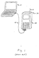
- FIG. 1 illustrates a prior art embodiment of a legacy architecture portable computer 10 that is coupled via a cable 12 to a portable telephone 14, as required by such a system.
- Portable telephone 14 provides RF transceiver functionality for portable computer 10.
- FIG 2 illustrates another prior art embodiment of a short distance RF communication system in which a legacy architecture portable computer 10 is coupled via a data cable 12 to a dedicated short distance RF communication module or device 16 (i.e., which is able to transmit and receive RF signals over a short distance - e.g., up to 10 meters).
- RF module or device 16 has an antenna 18 and RF circuitry 20 (typically transceiver functionality) coupled to antenna 18.
- RF circuitry 20 typically transceiver functionality
- portable computer 10, portable phone 14 and RF module or device 16 each require a power source for proper operation. While one or more of these devices may derive its power solely from batteries, the more common and practical practice is to have each device derive its power from batteries while the device is in a portable mode and from a power cord coupled to a conventional power supply when the device is near a permanent power supply.
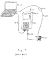
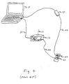
- Figures 3 and 4 illustrate the systems of Figures 1 and 2, respectively, in which portable computer 10, portable phone 14 and RF device 16 obtain their power from a power cord 22 coupled to a conventional power supply 24 (such as a power receptacle - for example, 110 VAC).
- Devices having an input voltage requirement less than the supply voltage may also have a step down transformer or voltage reducing circuit 26.
- a transformer or other voltage conversion or regulator circuitry may be used to reduce a supply voltage of 110 VAC, supplied by a power receptacle on a wall, to the required input voltage of the device.
- an AC/DC converter may also coupled between the step down transformer and the device.
- Rechargeable batteries may be recharged in one of three methods. First, batteries 28 within a portable electronic device may be physically removed from the device and placed in a battery recharge mechanism 30 until recharged, as illustrated in Figure 5. The batteries are replaced in the electronic device after being recharged.
- batteries 28 may be recharged within the electronic device it powers (in this case portable computer 10, portable telephone 14 or RF device 16) via a power cord 22 (typically having a transformer 26 at one end of the power cord - typically the portion that plugs into the power source) coupling the portable electronic device to a conventional power supply 24, as discussed above and illustrated in Figures 3 and 4.
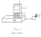
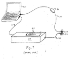
- batteries within small portable electronic devices, such as portable phone 14 may also be recharged within the device while the device is placed within a charging cradle or receptacle 32 that is coupled, via a power cord 22, to a conventional power supply 24, as illustrated in Figure 6.
- Removing a device's batteries for recharging is awkward and burdensome.
- the electronic device using the batteries is typically unusable - if of the battery only type - while its batteries are removed. There is also the potential problem of losing or damaging the batteries and/or the device itself through mishandling of the device or batteries and wear resulting from the continual process of removing and replacing batteries. If the device is of the type allowing operation from a power cord only, the mobility of the device is limited to the length of the power cord.
- the method of recharging batteries shown in Figures 3 and 4 is more convenient than the method of Figure 5 in that the batteries are not removed from the device while recharging, which facilitates immediate operation of the device, even if the batteries are not fully charged.
- the recharging cradle is the most convenient method of recharging.
- One disadvantage of the charging cradles of the prior art is that they require a power cable coupling the charging cradle to a dedicated power source, such as a 110VAC wall outlet or 12VDC outlet (such as an automotive cirgarette lighter power supply).
- a dedicated power source such as a 110VAC wall outlet or 12VDC outlet (such as an automotive cirgarette lighter power supply).
- Such recharging techniques are useless in situations where there are no, or insufficient, discrete power sources available to plug in the power cord of the charging cable.
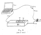
- FIG 7 illustrates a cradle 34 adapted to supply both power and data to an electronic device 14.
- cradle 34 has both a connector for power 36 and a data connector 38.
- cradle 34 has a single power and data connector 40 for coupling power (via cable 22) and data (via cable 12) to the portable phone 14.
- the invention disclosed herein comprises a method of using a mobile device-charging cradle to enable short distance wireless RF communication between a personal computer and at least one other short distance wireless RF communication enabled electronic device.
- a short distance wireless radio transmitter - Bluetooth in this example
- antenna are added to a charging cradle to produce a combination charging and short distance wireless communication enabled cradle which is coupled via a data cable to a personal computer.
- the short distance wireless (in this case RF) communication enabled cradle enables a system in which a legacy architecture personal computer may communicate with other short distance RF communication enabled electronic devices. Such communication is enabled whether or not another RF communication enabled portable electronic device is coupled to the cradle.
- a universal serial bus "USB" in a computer as a power source for the previously described cradle.
- a data/power cable couples a computer having an external USB connector to the short distance wireless communication enabled cradle.
- the cable includes electronic circuitry for converting the voltage level supplied by the USB to a voltage level usable by the cradle - including its Bluetooth radio and any peripheral electronic device that may be coupled to the cradle.
- Advantages of the above-described embodiments of the invention include: elimination of the need to purchase a Bluetooth enabled computer in order to enable Bluetooth communications between a non-Bluetooth enabled computer and another Bluetooth enabled electronic device; elimination of the need to purchase a Bluetooth enabled computer in order to enable Bluetooth communications between a Bluetooth enabled computer having disabled or disabled Bluetooth capability with another Bluetooth enabled electronic device; elimination of the need for a second power cable when the computer and the cradle are used together - saving both cost of acquiring the additional power cable and travel space; a reduction from two dedicated power sources (one for computer and one for the cradle) to one (for the computer only); and a convenient way to supply power to the cradle from the computer's batteries when no external power source is available for either device.
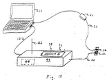
- FIG. 10 discloses a preferred embodiment of the invention in which an antenna 42 and an RF transceiver or radio 44 (a Bluetooth radio in the preferred embodiment, but could also be any other RF transceiver having a low power transmitter capable of short distance transmissions of less than 100m) are added to a charging cradle (such as charging cradle 34) to produce a combination charging and short distance communication (in this case Bluetooth) enabled cradle 46.
- a charging cradle such as charging cradle 34
- Figure 11 illustrates one technique for coupling the data cable 12 to a USB hub 43.
- USB hub 43 is coupled to radio 44 and to data connector 38.
- Power line 22 is coupled to power connector 36 and radio 44.
- Short distance RF communication enabled cradle 46 enables a system in which a legacy architecture personal computer 10 (to which it is coupled) to communicate to other short distance RF communication enabled electronic devices. Such communication is enabled whether or not another RF communication enabled portable electronic device is coupled to cradle 46.
- Figure 12 is a high-level block diagram of a system comprising personal computer 10, data cable 12 and cradle 46.
- Figure 13 illustrates the high level block diagram of the system of Figure 12 further including another short distance RF communication device 50, such as a computer system, PDA, keyboard, etc., which can communicate with short distance RF communication enabled system 48.
- Figure 14 illustrates the system of Figure 13 further including a mobile device without a Bluetooth radio 52.
- mobile device 52 is a cellular telephone that includes a transceiver and antenna to communicate with cellular telephone base stations, but is not otherwise enabled to communicate with low power short distance wireless devices.
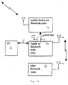
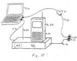
- Figure 15 illustrates a system implementation of the block diagram of Figure 14.
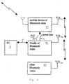
- Figure 16 illustrates the system of Figure 13 further including a mobile device with a Bluetooth radio 54.
- mobile device 54 is a cellular telephone that includes a transceiver and antenna to communicate with cellular telephone base stations and includes a transceiver and antenna to communicate with low power short distance wireless devices.
- Figure 17 illustrates a system implementation of the block diagram of Figure 16.
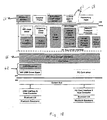
- Figure 18 illustrates a high level block diagram of the relevant portions of personal computer 10 that enable the computer to communicate with the Bluetooth radio in cradle 46.
- Computer 10 includes a bus driver 56 (one example being shown on Figure 3, page 12, of the WinHEC 99 White Page Bluetooth Radio System Overview, hereby incorporated by reference).
- RF Communication 58 emulates a serial port to personal computer 10 (or, as an alternative, it can interface to the Network Transport Protocols, as shown in Figure 3 of the WinHEC 99 White Page Bluetooth Radio System Overview). As a result, a PC application programmer only sees the serial port, not the Bluetooth connection that is behind the serial port.
- Bluetooth profiles 60 such as found in the Bluetooth Profile Specification, which can be found at www.Bluetooth.com or www.Bluetooth.net, hereby incorporated by reference, which are applications that insure compatibility between devices - not just at the physical layer or protocol layer, but compatibility at the application layer so that if, for example, data synchronization is required, the computer knows how to do data synchronization with mobile device 54 (see for example, Fig. 21 in the Profile Stack section on page 171 of the Bluetooth Profile Specification).
- Computer 10 can be enhanced by the addition of an application 60 that enables the user to configure, control, and use all Bluetooth devices that are connected to a computer (e.g., application such as Bluetooth Advisor - see WinHEC 99 White Paper submitted herewith, or Bluetooth Neighborhood - see also www.Bluetooth.net).
- application such as Bluetooth Advisor - see WinHEC 99 White Paper submitted herewith, or Bluetooth Neighborhood - see also www.Bluetooth.net.
- USB Universal Serial Bus
- the computer 10 also requires a USB driver 62 in addition to a PC operating system 61, such as Microsoft's Windows 98.
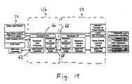
- FIG 19 is a high-level block diagram of the relevant elements of cradle 46.
- cradle 46 requires a bus driver. If computer 10 is to be coupled to cradle 46 via a Universal Serial Bus "USB", cradle 46 will require a USB driver 62.
- USB driver 62 is coupled to HCI 64 (which is a set of commands that describes how the cradle communicates with the computer - an example of which can also be see in HCI USB Transport Layer - addendum to the HCI document - in particular Figure 1.2 on page 753 of the Bluetooth Specification Version 1.08, hereby incorporated by reference - or in general Host Controller Interface Functional Specification page 516-748, also incorporated by reference).
- HCI 64 which is a set of commands that describes how the cradle communicates with the computer - an example of which can also be see in HCI USB Transport Layer - addendum to the HCI document - in particular Figure 1.2 on page 753 of the Bluetooth Specification Version 1.08, hereby
- USB driver 62 and HCI 64 are further coupled to a Link Manager (carries control information exchange between the Link Manager master and slave - one example being shown on page 77 or the Bluetooth Baseband Specification - see also pages 191-244) and a Link Controller 66 (carries low level link control information like ARQ flow control and payload characterization - one example being shown on page 77 of the Bluetooth Baseband Specification and otherwise discussed in the Bluetooth Baseband Specification) and to a Bluetooth Base Band processor 68 (such as a BSN 6020 Base Band processor available from Texas Instruments).
- the Blue tooth applications do not run on the phone. For example, on computer 10, you can implement an application called "Bluetooth Advisor" or something similar.
- Bluetooth Advisor which, when selected, utilizes a data sync profile to work with a service discovery profile, which would list all of the devices around computer 10 that are Bluetooth devices. All of the Bluetooth software stack below HCI is performed by the Bluetooth radio on cradle 46. The software below the host controller interface is run on the radio in cradle 46. The rest is run on computer 10's processor. The result to computer 10 is the same as if computer 10 were itself short distance RF wireless communication enabled.
- An advantage of the present invention is that it enables Legacy architecture computers (PC without Bluetooth) to now become Bluetooth enabled. It also enables a Bluetooth enabled computer, having a defective or disabled Bluetooth capability, to become Bluetooth enabled.
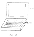
- FIG. 20 illustrates a portable computer 70 equipped with at least one universal serial bus "USB" connector 72.
- USB connector 72 is coupled to a USB within computer 70 (not shown).
- Universal serial bus is defined in the Universal Serial Bus Specification Revision 1.1, September 23, 1998, incorporated herein by reference.
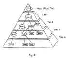
- Figure 21 illustrates a bus topology of the USB.
- the USB connects USB devices with the USB host.
- the USB physical interconnect is a tiered star topology.
- a hub is at the center of each star.
- Each wire segment is a point-to-point connection between the host and a hub or function, or a hub connected to another hub or function.
- the USB interface to the host computer system is referred to as the Host Controller.
- the Host Controller may be implemented in a combination of hardware, firmware, or software.
- a root hub is integrated within the host system to provide one or more attachment points.
- USB devices are one of the following: hubs, which provide additional attachment points to the USB; or functions, which provide capabilities to the system, such as an ISDN connection, a digital joystick, speakers, etc.
- USB devices present a standard USB interface in terms of the following: their comprehension of the USB protocol; their response to standard USB operations, such as configuration and reset; and their standard capability descriptive information.
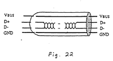
- the USB transfers signal and power over a four-wire cable, shown in Figure 22.
- the signal occurs over two wires on each point-to-point segment.
- the low-speed mode requires less EMI protection. Both modes can be supported in the same USB bus by automatic dynamic mode switching between transfers.
- the low-speed mode is defined to support a limited number of low-bandwidth devices, such as mice, because general use would degrade bus utilization.
- the clock is transmitted, encoded along with the differential data.
- the clock-encoding scheme is NRZI with bit stuffing to ensure adequate transitions.
- the cable also carries Vbus is nominally +5V at the source.
- the USB allows cable segments of variable lengths, up to several meters, by choosing the appropriate conductor gauge to match the specified IR drop and other attributes such as device power budget and cable flexibility.
- biased terminations are used at each end of the cable. The terminations also permit the detection of attach and detach at each port and differentiate between full-speed and low-speed devices.
- a low power function is one that draws up to one unit load from the USB cable when operational.
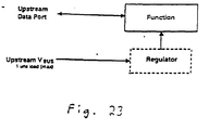
- Figure 23 shows a typical bus-powered, low-power function, such as a mouse. Low-power regulation can be integrated into the function silicon. Low-power functions must be capable of operating with input Vbus voltages as low as 4.40V, measured at the end of the cable.
- a function is defined as being high-power if, when fully powered, it draws over one but less than five unit loads from the USB cable.
- a high-power function requires staged switching of power. It must first come up in a reduced power state of less than one unit load. At bus enumeration time, its total power requirements are obtained and compared against the available power budget. If sufficient power exists, the remainder of the function may be powered on.
- a typical high-power function is shown in Figure 24.
- the function's electronics have been partitioned into two sections. The function controller contains the minimum amount of circuitry necessary to permit enumeration and power budgeting. The remainder of the function resides in the function block.
- High-power functions must be capable of operating in their low-power (one unit load) mode with an input voltage as low as 4.40V, so that it may be detected and enumerated even when plugged into a bus-powered hub. They must also be capable of operating at full power (up to five unit loads) with a Vbus voltage of 4.75V, measured at the upstream plug end of the cable.
- the universal serial bus in a computer has power lines (+4.5 VDC and GND), which may be tapped to power a peripherally coupled Bluetooth radio and any other peripherally coupled portable electronic device, such as cellular telephone.
- Figure 25 illustrates a system for using the voltage available on a universal serial bus in computer 70 as the source of power for Bluetooth radio 44 in cradle 74, while also providing a source of power to connector 36 to provide a source a power for any peripheral portable electronic device coupled to connector 36.
- electronic circuitry within a connector 76 couples a USB connector 70 on portable computer 70 to a four-conductor cable 78 (for power and data).
- Power and data cable 78 is connected to cradle 74 wherein two data lines of cable 78 are connected to a USB function controller 80. Two power lines of cable 78 are connected to Bluetooth radio 44, USB function controller 80 and power connector 36. Electronic circuitry within connector 76 converts the voltage outputted by the USB of computer 70 to a voltage that may be used to power Bluetooth radio 44, USB function controller 80 and power connector 36. As an alternative embodiment, the electronic circuitry for converting the voltage outputted by the USB of computer 70 could be placed in cradle 74 instead of in connector 76.
- Figure 26 illustrates the system of Figure 25 and further illustrates the power and data cable connections between the components within cradle 74.
- FIG. 27 is a block diagram of the electronic circuitry 82 within connector 76.
- Electronic circuitry 82 comprises a voltage regulator 84 having a first lead 86 coupled, via a conductor in USB connector 76, to receive the +4.5 VDC available on the USB of portable computer 70, and a second lead 88 coupled, via another conductor in USB connector 76, to ground.
- Connector 76 further has a third lead 90 coupled to a first data line in connector 70 and a fourth lead 92 coupled to a second data line in connector 70.
- Regulator 84 further has a first output coupled to the +VDC lead line of cable 78 and a second output coupled to the "GND" lead line of cable 78.
- Data lines 90 and 92 extend into the D+ and D- lead lines of cable 78.
- circuitry 82 is disclosed as being within connector 76, which is directly connected to connector 72 on computer 70 in the present embodiment, circuitry 82 could just as easily be placed in a module spaced anywhere in the cable coupling connector 72 to cradle 74 or in cradle 74 itself.
- Figure 28 discloses an embodiment of the invention in which circuitry 82 is in a module or protective case 94 coupled to connector 72 via a first four-wire cable 78. Circuitry 82 is further connected to cradle 74 via a second four-wire cable 78.
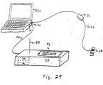
- Figure 29 discloses an embodiment of the invention in which cradle 74 has a combined power/data connector.
- the power and data leads of cable 78 terminate in connector 96, which couples to the corresponding power/data connector in a peripheral coupled electronic device, such as cellular phone 52 (or 54).
- All embodiments of the invention facilitate the elimination of a need for a power cable that couples cradle 74 to a dedicated power source - which eliminates the expense of the cable, and the extra room required to transport the cable during mobile operations.
- the invention facilitates using the power available on a universal serial bus in a computer as the power source for powering a Bluetooth radio, a USB function controller and a peripherally coupled portable electronic device (which facilitates recharging of the device's batteries).
- the USB is able to accommodate the power needs of Bluetooth radio 44, USB function controller 80 and a peripherally coupled portable electronic device (such as phone 52 or 54) since computer 70 has a voltage converter or regulator, which can provide for the additional demands of these devices.
- the USB controller in the cradle 74 contains at least the minimum amount of circuitry for a USB function controller to permit enumeration and power budgeting.
- a USB host in the computer but no USB function controller (in general there is always a USB host in a USB enabled computer while the USB function controllers are in the devices that are connected to the computer via USB cable. Therefore, the circuitry must enumerate the USB device (which in this case is the connector), in order to draw current out of the USB port on the computer.
- the actual amount of current drawn could vary from, e.g., 1...5 unit loads or the USB function controller could negotiate with the USB host the maximum amount of current the host will grant to the connector, and convert the voltage level from Vbus to whatever voltage level is required by the phone. The result is cost and space savings.
- Yet another advantage of the present invention is the fact that Bluetooth radio 44, USB function controller 80 and a peripherally coupled portable electronic device (such as phone 52 or 54) can draw power from computer 70 while computer 70 is running solely on its batteries - e.g., no power source is available to plug into. This is an important advantage while traveling. Indeed, in such a situation where the computer is running on battery power, only one cable is required to supply power and data to cradle 74.
Landscapes
- Engineering & Computer Science (AREA)
- Theoretical Computer Science (AREA)
- General Engineering & Computer Science (AREA)
- Power Engineering (AREA)
- Computer Hardware Design (AREA)
- Physics & Mathematics (AREA)
- General Physics & Mathematics (AREA)
- Telephone Function (AREA)
- Charge And Discharge Circuits For Batteries Or The Like (AREA)
- Power Sources (AREA)
- Telephone Set Structure (AREA)
- Telephonic Communication Services (AREA)
- Mobile Radio Communication Systems (AREA)
Applications Claiming Priority (2)
| Application Number | Priority Date | Filing Date | Title |
|---|---|---|---|
| US09/476,986 US6255800B1 (en) | 2000-01-03 | 2000-01-03 | Bluetooth enabled mobile device charging cradle and system |
| US476986 | 2000-01-03 |
Publications (2)
| Publication Number | Publication Date |
|---|---|
| EP1122648A2 true EP1122648A2 (fr) | 2001-08-08 |
| EP1122648A3 EP1122648A3 (fr) | 2004-05-26 |
Family
ID=23894035
Family Applications (1)
| Application Number | Title | Priority Date | Filing Date |
|---|---|---|---|
| EP01200003A Withdrawn EP1122648A3 (fr) | 2000-01-03 | 2001-01-03 | Procedé pour la réalisation et/ou l'utilisation d' un support-chargeur pour un appareil mobile |
Country Status (3)
| Country | Link |
|---|---|
| US (1) | US6255800B1 (fr) |
| EP (1) | EP1122648A3 (fr) |
| JP (1) | JP2001274878A (fr) |
Cited By (2)
| Publication number | Priority date | Publication date | Assignee | Title |
|---|---|---|---|---|
| GB2366952A (en) * | 2000-01-28 | 2002-03-20 | Mitel Telecom Ltd | Short range base stations connected to main power wiring |
| GB2377136A (en) * | 2001-06-28 | 2002-12-31 | Nec Corp | Mobile telephone inter-connecting apparatus |
Families Citing this family (146)
| Publication number | Priority date | Publication date | Assignee | Title |
|---|---|---|---|---|
| US20080043675A1 (en) * | 1998-05-29 | 2008-02-21 | Research In Motion Limited | System and Method for Redirecting Data to a Wireless Device Over a Plurality of Communication Paths |
| US7606936B2 (en) * | 1998-05-29 | 2009-10-20 | Research In Motion Limited | System and method for redirecting data to a wireless device over a plurality of communication paths |
| JP3297389B2 (ja) * | 1998-12-07 | 2002-07-02 | インターナショナル・ビジネス・マシーンズ・コーポレーション | 消費電力制御方法および電気機器 |
| US6728546B1 (en) * | 1999-03-23 | 2004-04-27 | Legerity, Inc. | Computer peripheral base station for a cordless telephone |
| JP2000316006A (ja) * | 1999-04-28 | 2000-11-14 | Nec Corp | バスマネージャ機能自動切換対応ノード、移動端末、及び、移動端末システム |
| US6633932B1 (en) * | 1999-09-14 | 2003-10-14 | Texas Instruments Incorporated | Method and apparatus for using a universal serial bus to provide power to a portable electronic device |
| US6405027B1 (en) * | 1999-12-08 | 2002-06-11 | Philips Electronics N.A. Corporation | Group call for a wireless mobile communication device using bluetooth |
| US6446118B1 (en) * | 2000-02-29 | 2002-09-03 | Designtech International, Inc. | E-mail notification device |
| JP3485060B2 (ja) * | 2000-03-08 | 2004-01-13 | 日本電気株式会社 | 情報処理端末装置及びそれに用いる携帯電話端末接続方法 |
| KR100612004B1 (ko) * | 2000-04-06 | 2006-08-11 | 삼성전자주식회사 | Bluetooth 무선 통신을 지원하는 통신장치에서의 수신 데이터 처리 방법 |
| US6766160B1 (en) * | 2000-04-11 | 2004-07-20 | Nokia Corporation | Apparatus, and associated method, for facilitating authentication of communication stations in a mobile communication system |
| US6643336B1 (en) * | 2000-04-18 | 2003-11-04 | Widcomm, Inc. | DC offset and bit timing system and method for use with a wireless transceiver |
| US7389334B2 (en) * | 2000-04-24 | 2008-06-17 | Microsoft Corporation | Exposing bluetooth compliant wireless device connection as modems or sockets |
| US6714797B1 (en) * | 2000-05-17 | 2004-03-30 | Nokia Corporation | System and method for the transfer of digital data to a mobile device |
| JP3789725B2 (ja) * | 2000-05-26 | 2006-06-28 | 富士通株式会社 | 通信デバイス |
| WO2001097453A1 (fr) * | 2000-06-13 | 2001-12-20 | Red-M (Communications) Limited | Adaptateur bluetooth |
| US6874037B1 (en) * | 2000-06-19 | 2005-03-29 | Sony Corporation | Method and apparatus for synchronizing device information |
| US6731751B1 (en) * | 2000-06-27 | 2004-05-04 | Vxi Corporation | Apparatus for cordless computer telephony |
| EP1175111A1 (fr) * | 2000-07-17 | 2002-01-23 | Lucent Technologies Inc. | Système de communication en réseau sans fil et appareil pour utilisation dans ce système de communication en réseau sans fil |
| US7207059B1 (en) * | 2000-08-16 | 2007-04-17 | Hewlett-Packard Development Company, L.P. | Wireless communication system utilizing antenna dongle |
| JP4689812B2 (ja) * | 2000-11-17 | 2011-05-25 | 富士通コンポーネント株式会社 | ワイヤレスマウス |
| JPWO2002051039A1 (ja) * | 2000-12-21 | 2004-04-22 | 松下電器産業株式会社 | 無線システム、無線装置、無線接続方法、プログラム、および媒体 |
| US6936936B2 (en) * | 2001-03-01 | 2005-08-30 | Research In Motion Limited | Multifunctional charger system and method |
| US6946817B2 (en) * | 2001-03-01 | 2005-09-20 | Research In Motion Limited | System and method for powering and charging a mobile communication device |
| JP3533376B2 (ja) * | 2001-03-16 | 2004-05-31 | 多摩川精機株式会社 | 回転型非接触コネクタ |
| US20020140690A1 (en) * | 2001-03-30 | 2002-10-03 | Gamsaragan Edward V. | Computer with communicating separable computing display subsystem |
| US7269183B2 (en) * | 2001-04-27 | 2007-09-11 | Broadcom Corporation | System and method for connecting bluetooth-enabled devices to a personal computer |
| US6926130B2 (en) * | 2001-05-08 | 2005-08-09 | Restech, Inc. | Portable docking station and cord reel assembly |
| US6892051B2 (en) * | 2001-06-25 | 2005-05-10 | Cingular Wireless Ii, Llc | System and method for providing an adapter module |
| US6636749B2 (en) * | 2001-06-25 | 2003-10-21 | At&T Wireless Services, Inc. | Method and apparatus for providing power and wireless protocol capability to a wireless device, such as a wireless phone |
| US6889065B2 (en) * | 2001-06-25 | 2005-05-03 | Cingular Wireless Ii, Llc | System and method for providing an adapter module |
| US7103760B1 (en) * | 2001-07-16 | 2006-09-05 | Billington Corey A | Embedded electronic device connectivity system |
| US6362610B1 (en) * | 2001-08-14 | 2002-03-26 | Fu-I Yang | Universal USB power supply unit |
| US20030036351A1 (en) * | 2001-08-16 | 2003-02-20 | Leonard Forbes | Portable memory module, and method of portable data transfer |
| EP1428134A2 (fr) * | 2001-08-22 | 2004-06-16 | Peerless Systems Corporation | Systeme et procede de gestion de sortie permettant l'impression via des dispositifs sans fil |
| US20030078965A1 (en) * | 2001-08-22 | 2003-04-24 | Cocotis Thomas A. | Output management system and method for enabling printing via wireless devices |
| KR100866239B1 (ko) * | 2001-10-23 | 2008-10-30 | 삼성전자주식회사 | 블루투스 외장형 모뎀 겸용 헤드셋 및 그 제어 방법 |
| US7164886B2 (en) * | 2001-10-30 | 2007-01-16 | Texas Instruments Incorporated | Bluetooth transparent bridge |
| US6498458B1 (en) * | 2001-11-01 | 2002-12-24 | Cliff Chen | Battery charger for charging a wireless signal source and detachable receiver |
| US7555287B1 (en) | 2001-11-01 | 2009-06-30 | Nokia Corporation | Customized messaging between wireless access point and services |
| US20030087601A1 (en) * | 2001-11-05 | 2003-05-08 | Aladdin Knowledge Systems Ltd. | Method and system for functionally connecting a personal device to a host computer |
| US20030092384A1 (en) * | 2001-11-14 | 2003-05-15 | Ross W. Anthony | Piconetwork radiotelephone interfaces for vehicles including wireless pointing and display devices |
| JP3625799B2 (ja) * | 2001-11-30 | 2005-03-02 | 三洋電機株式会社 | 真贋判別回路を備えるパック電池 |
| US7483403B2 (en) * | 2002-01-10 | 2009-01-27 | Robert Bosch Gmbh | Protocol for reliable, self-organizing, low-power wireless network for security and building automation systems |
| US20030151513A1 (en) * | 2002-01-10 | 2003-08-14 | Falk Herrmann | Self-organizing hierarchical wireless network for surveillance and control |
| KR100539530B1 (ko) * | 2002-02-01 | 2005-12-30 | 엘지전자 주식회사 | 일체형 무선 가입자 망 단말기 |
| US7340214B1 (en) * | 2002-02-13 | 2008-03-04 | Nokia Corporation | Short-range wireless system and method for multimedia tags |
| US6920337B2 (en) * | 2002-03-01 | 2005-07-19 | Hewlett-Packard Development Company, L.P. | Apparatus, system, and method for wireless notifications |
| US6844813B2 (en) * | 2002-03-08 | 2005-01-18 | Vending Management Services Limited | Cooperative vending machine data reporting |
| US7102640B1 (en) * | 2002-03-21 | 2006-09-05 | Nokia Corporation | Service/device indication with graphical interface |
| US6664758B2 (en) * | 2002-03-29 | 2003-12-16 | Fu-I Yang | Universal power adapter |
| US6876838B1 (en) * | 2002-04-26 | 2005-04-05 | Methode Electronics, Inc. | Electrical transceiver module with alternate peripheral device connector |
| US20030207703A1 (en) * | 2002-05-03 | 2003-11-06 | Liou Ruey-Ming | Multi-purpose wireless communication device |
| US6895445B2 (en) * | 2002-05-28 | 2005-05-17 | Mercurymd, Inc. | Docking stations for transferring data between handheld electronic devices and other devices via infrared communications |
| US7135987B1 (en) | 2002-06-03 | 2006-11-14 | Gsi Group Corporation | Wireless chart recorder system and method |
| EP1777642A1 (fr) | 2002-06-04 | 2007-04-25 | Mineral Lassen LLC | Transmission d'informations en utilisant des transpondeurs à rétrodiffusion |
| US7697946B2 (en) * | 2002-06-04 | 2010-04-13 | Forster Ian J | Reflective communication using radio-frequency devices |
| US20030233590A1 (en) * | 2002-06-17 | 2003-12-18 | Henry Liu | Conversion device bult in with signal and level conversion circuits |
| FR2841425B1 (fr) * | 2002-06-20 | 2004-09-24 | Cit Alcatel | Procede de fourniture de donnees de configuration de service a un dispositif de telephonie mobile, par un terminal informatique |
| FR2841699B1 (fr) * | 2002-07-01 | 2005-10-14 | France Telecom | Chargeur et dispositif de recharge |
| US20040023686A1 (en) * | 2002-07-31 | 2004-02-05 | Lavaflow, Llp | Method of and apparatus for outputting a picture file |
| US20040044913A1 (en) * | 2002-08-29 | 2004-03-04 | Wu Kuang Ming | Method for coordinating built-in bluetooth modules |
| US6794845B2 (en) * | 2002-09-17 | 2004-09-21 | Motorola, Inc. | Charging device for charging a plurality of devices |
| JP4338170B2 (ja) * | 2002-09-30 | 2009-10-07 | キヤノン株式会社 | 画像形成装置 |
| US6909946B1 (en) | 2002-10-31 | 2005-06-21 | Garmin Ltd. | System and method for wirelessly linking electronic marine components |
| US20070077926A1 (en) * | 2005-09-30 | 2007-04-05 | Arati Manjeshwar | Method and system to reconfigure a network to improve network lifetime using most reliable communication links |
| US7525291B1 (en) * | 2003-01-21 | 2009-04-28 | Microsemi Corporation | Linearly regulated battery charger |
| US20040198464A1 (en) * | 2003-03-04 | 2004-10-07 | Jim Panian | Wireless communication systems for vehicle-based private and conference calling and methods of operating same |
| US20040181517A1 (en) * | 2003-03-13 | 2004-09-16 | Younghee Jung | System and method for social interaction |
| USD486829S1 (en) | 2003-03-28 | 2004-02-17 | Tai-Chang Wang | Bluetooth USB dongle |
| US20040267883A1 (en) * | 2003-06-27 | 2004-12-30 | Nokia Corporation | Repository for a mobile telephone |
| US7671803B2 (en) * | 2003-07-25 | 2010-03-02 | Hewlett-Packard Development Company, L.P. | Wireless communication system |
| US6927970B2 (en) * | 2003-07-31 | 2005-08-09 | International Business Machines Corporation | Universal infrared coupling device |
| US6975884B2 (en) * | 2003-08-20 | 2005-12-13 | Motorola, Inc. | Wireless local area network vehicular adapter |
| DE20314317U1 (de) * | 2003-09-16 | 2003-11-20 | Audioton Kabelwerk GmbH Zweigniederlassung Scheinfeld, 91443 Scheinfeld | Verbindungssystem, Grundteil und Adapterteil zur Verbindung von Mobilfunk-Endgeräten |
| JP2005242717A (ja) * | 2004-02-26 | 2005-09-08 | Toshiba Corp | 記録装置、記録方法及び記録システム |
| US20050278756A1 (en) * | 2004-06-12 | 2005-12-15 | Brown Alan E | Information processing apparatus featuring a multi-subsystem wireless bus architecture |
| GB2416718A (en) * | 2004-07-29 | 2006-02-08 | Eminox Ltd | Gas treatment apparatus |
| US20060068857A1 (en) * | 2004-07-30 | 2006-03-30 | Asseily Alexander M | Hybrid mobile headset |
| US8085962B2 (en) * | 2004-09-01 | 2011-12-27 | Bose Corporation | Audio system for portable device |
| US8103033B2 (en) * | 2004-09-01 | 2012-01-24 | Bose Corporation | Audio system for portable device |
| US20060100841A1 (en) * | 2004-09-02 | 2006-05-11 | Tung-Ho Wu | Automatic system and method for testing mobile phone |
| US20060274037A1 (en) * | 2005-06-06 | 2006-12-07 | Stewart Sheila K | Onboard pointer system |
| US20060075075A1 (en) * | 2004-10-01 | 2006-04-06 | Malinen Jouni I | Method and system to contextually initiate synchronization services on mobile terminals in an enterprise environment |
| US7664027B2 (en) * | 2004-10-20 | 2010-02-16 | Sigmatel, Inc. | Infrared adapter with data packet throttle |
| KR100703408B1 (ko) * | 2004-12-06 | 2007-04-03 | 삼성전자주식회사 | 가로 거치 겸용 세로 거치 유형 충전 거치대 |
| US7539513B2 (en) | 2005-02-02 | 2009-05-26 | National Telephone Products, Inc. | Portable phone with ergonomic image projection system |
| US20060223579A1 (en) * | 2005-04-04 | 2006-10-05 | Parrish Whitaker | Universal battery charger and data transfer system |
| DE102005015265A1 (de) * | 2005-04-04 | 2006-10-05 | Robert Bosch Gmbh | Ladeeinheit mit einer Übertragungseinheit |
| GB2425490A (en) * | 2005-04-26 | 2006-11-01 | Steven Lipman | Wireless communication toy |
| TWI273782B (en) * | 2005-07-25 | 2007-02-11 | Sin Etke Technology Co Ltd | Short-distance wireless transmission system of electric device in vehicle |
| US7925320B2 (en) | 2006-03-06 | 2011-04-12 | Garmin Switzerland Gmbh | Electronic device mount |
| US7574187B2 (en) * | 2006-05-30 | 2009-08-11 | Sony Ericsson Mobile Communications Ab | Battery charger antenna, method and device incorporating the same |
| JP4864609B2 (ja) * | 2006-08-28 | 2012-02-01 | ルネサスエレクトロニクス株式会社 | データ通信用アダプタ及び無線通信モジュール |
| KR100836634B1 (ko) * | 2006-10-24 | 2008-06-10 | 주식회사 한림포스텍 | 무선 데이타 통신과 전력 전송이 가능한 무접점 충전장치,충전용 배터리팩 및 무접점 충전장치를 이용한 휴대용단말기 |
| US20080203968A1 (en) * | 2007-02-28 | 2008-08-28 | Campbell Christopher D | Multiple charging unit |
| US20080305758A1 (en) * | 2007-06-05 | 2008-12-11 | Hatch Thomas W | Wireless computer mouse receiver |
| US20090006699A1 (en) * | 2007-06-28 | 2009-01-01 | Broadcom Corporation | Universal serial bus dongle device with global positioning and system for use therewith |
| GB0714148D0 (en) | 2007-07-19 | 2007-08-29 | Lipman Steven | interacting toys |
| US8351629B2 (en) * | 2008-02-21 | 2013-01-08 | Robert Preston Parker | Waveguide electroacoustical transducing |
| US8295526B2 (en) * | 2008-02-21 | 2012-10-23 | Bose Corporation | Low frequency enclosure for video display devices |
| US7913020B2 (en) * | 2008-04-29 | 2011-03-22 | Bose Corporation | Automated exchangeable docking configuration |
| US7910833B2 (en) | 2008-05-27 | 2011-03-22 | Voltstar Technologies, Inc. | Energy-saving power adapter/charger |
| US7960648B2 (en) | 2008-05-27 | 2011-06-14 | Voltstar Technologies, Inc. | Energy saving cable assemblies |
| US7910834B2 (en) * | 2008-05-27 | 2011-03-22 | Voltstar Technologies, Inc. | Energy saving cable assemblies |
| US20090319644A1 (en) * | 2008-06-19 | 2009-12-24 | Symbol Technologies, Inc. | Methods and apparatus for automatically configuring computing devices for wireless network connections |
| CA2739200A1 (fr) * | 2008-07-11 | 2010-01-14 | Bby Solutions, Inc. | Clef usb dongle de haut-parleur sans fil avec sortie audio auxiliaire |
| US8335546B2 (en) | 2008-12-19 | 2012-12-18 | Harris Technology, Llc | Portable telephone with connection indicator |
| US20100194197A1 (en) * | 2009-02-04 | 2010-08-05 | Kung-Neng Lee | Power converter with communication capability |
| US8742814B2 (en) | 2009-07-15 | 2014-06-03 | Yehuda Binder | Sequentially operated modules |
| US20110021147A1 (en) * | 2009-07-21 | 2011-01-27 | Tout Walid R | System and method for determining connectivity status of short range wireless devices |
| CN102012883B (zh) * | 2009-09-07 | 2012-09-12 | 郑国书 | 无线电射频同步通讯的方法 |
| US20110095728A1 (en) | 2009-10-28 | 2011-04-28 | Superior Communications, Inc. | Method and apparatus for recharging batteries in a more efficient manner |
| JP5570053B2 (ja) * | 2009-12-25 | 2014-08-13 | パナソニック株式会社 | 電子機器 |
| US20110167180A1 (en) * | 2010-01-06 | 2011-07-07 | Clear Wireless Llc | Antenna docking station |
| US9178363B2 (en) | 2010-01-26 | 2015-11-03 | Broadcom Corporation | Smart powering and pairing system and related method |
| US9153995B2 (en) * | 2010-01-26 | 2015-10-06 | Broadcom Corporation | Smart power delivery system and related method |
| US8265310B2 (en) * | 2010-03-03 | 2012-09-11 | Bose Corporation | Multi-element directional acoustic arrays |
| US20110230209A1 (en) * | 2010-03-22 | 2011-09-22 | Dsp Group Ltd. | Method and Mobile Device for Automatic Activation of Applications |
| PL2563172T5 (pl) * | 2010-04-30 | 2022-08-29 | Fontem Holdings 4 B.V. | Urządzenie elektroniczne do palenia |
| US8553894B2 (en) | 2010-08-12 | 2013-10-08 | Bose Corporation | Active and passive directional acoustic radiating |
| EP3584675B1 (fr) * | 2011-01-11 | 2023-10-18 | Avago Technologies International Sales Pte. Limited | Système d'alimentation et d'appariement intelligent et procédé associé |
| US9525293B2 (en) | 2011-12-30 | 2016-12-20 | Makita Corporation | Battery charger having angled wall in battery receiving opening, and battery pack charging system and cordless power tool system including same |
| US9490648B2 (en) | 2012-04-30 | 2016-11-08 | Hewlett-Packard Development Company, L.P. | Alternating current direct current adapter with wireless charging |
| US9781496B2 (en) | 2012-10-25 | 2017-10-03 | Milwaukee Electric Tool Corporation | Worksite audio device with wireless interface |
| CN103219771B (zh) * | 2013-04-24 | 2015-04-22 | 山东比特电子工业有限公司 | 一种可与固定电话连接的充电设备 |
| US10281953B2 (en) | 2013-11-29 | 2019-05-07 | Motiv Inc. | Wearable device and data transmission method |
| EP3074838A4 (fr) | 2013-11-29 | 2017-08-02 | Motiv Inc. | Dispositif informatique vestimentaire |
| CN103973854A (zh) * | 2014-04-22 | 2014-08-06 | 魏家满 | 移动个人通信设备指环支架 |
| USD756999S1 (en) | 2014-06-02 | 2016-05-24 | Motiv Inc. | Wearable computing device |
| EP4183282B1 (fr) | 2014-12-25 | 2025-12-17 | Fontem Ventures B.V. | Gestion dynamique de puissance de sortie pour dispositif à fumer électronique |
| US10057701B2 (en) | 2015-03-31 | 2018-08-21 | Bose Corporation | Method of manufacturing a loudspeaker |
| US9451355B1 (en) | 2015-03-31 | 2016-09-20 | Bose Corporation | Directional acoustic device |
| WO2016161454A1 (fr) | 2015-04-03 | 2016-10-06 | Pinn, Inc. | Station multimédia personnelle sans fil |
| US10551498B2 (en) | 2015-05-21 | 2020-02-04 | Navico Holding As | Wireless sonar device |
| US9759813B2 (en) | 2015-06-22 | 2017-09-12 | Appetite Lab Inc. | Devices and methods for locating and visualizing underwater objects |
| US10578706B2 (en) | 2015-08-06 | 2020-03-03 | Navico Holding As | Wireless sonar receiver |
| US9401158B1 (en) | 2015-09-14 | 2016-07-26 | Knowles Electronics, Llc | Microphone signal fusion |
| US9779716B2 (en) | 2015-12-30 | 2017-10-03 | Knowles Electronics, Llc | Occlusion reduction and active noise reduction based on seal quality |
| US9830930B2 (en) | 2015-12-30 | 2017-11-28 | Knowles Electronics, Llc | Voice-enhanced awareness mode |
| US9812149B2 (en) | 2016-01-28 | 2017-11-07 | Knowles Electronics, Llc | Methods and systems for providing consistency in noise reduction during speech and non-speech periods |
| US20180062399A1 (en) * | 2016-03-18 | 2018-03-01 | Battery-Biz Inc. | Power supply system |
| JP6738016B2 (ja) * | 2016-07-27 | 2020-08-12 | 富士通クライアントコンピューティング株式会社 | 拡張装置、システム及びプログラム |
| US10719077B2 (en) | 2016-10-13 | 2020-07-21 | Navico Holding As | Castable sonar devices and operations in a marine environment |
| TWM578888U (zh) * | 2017-12-18 | 2019-06-01 | 光興國際股份有限公司 | 小型熱插拔收發裝置 |
| US11103013B2 (en) | 2018-09-07 | 2021-08-31 | Fontem Holdings 1 B.V. | Pivotable charging case for electronic smoking device |
Family Cites Families (6)
| Publication number | Priority date | Publication date | Assignee | Title |
|---|---|---|---|---|
| US5561282A (en) * | 1993-04-30 | 1996-10-01 | Microbilt Corporation | Portable signature capture pad |
| US5892949A (en) * | 1996-08-30 | 1999-04-06 | Schlumberger Technologies, Inc. | ATE test programming architecture |
| US5959287A (en) * | 1997-04-23 | 1999-09-28 | Lxe Inc. | Apparatus and method for supporting a cradle |
| US6016476A (en) * | 1997-08-11 | 2000-01-18 | International Business Machines Corporation | Portable information and transaction processing system and method utilizing biometric authorization and digital certificate security |
| US6028764A (en) * | 1998-09-28 | 2000-02-22 | Intel Corporation | Portable computer with separable screen |
| US6023241A (en) * | 1998-11-13 | 2000-02-08 | Intel Corporation | Digital multimedia navigation player/recorder |
-
2000
- 2000-01-03 US US09/476,986 patent/US6255800B1/en not_active Expired - Lifetime
-
2001
- 2001-01-03 EP EP01200003A patent/EP1122648A3/fr not_active Withdrawn
- 2001-01-04 JP JP2001000228A patent/JP2001274878A/ja not_active Abandoned
Cited By (4)
| Publication number | Priority date | Publication date | Assignee | Title |
|---|---|---|---|---|
| GB2366952A (en) * | 2000-01-28 | 2002-03-20 | Mitel Telecom Ltd | Short range base stations connected to main power wiring |
| GB2377136A (en) * | 2001-06-28 | 2002-12-31 | Nec Corp | Mobile telephone inter-connecting apparatus |
| GB2377136B (en) * | 2001-06-28 | 2005-01-05 | Nec Corp | Mobile radiotelephone connecting apparatus and mobile radiotelephone connecting system |
| US7020466B2 (en) | 2001-06-28 | 2006-03-28 | Nec Corporation | Mobile radiotelephone connecting apparatus and mobile radiotelephone connecting system |
Also Published As
| Publication number | Publication date |
|---|---|
| JP2001274878A (ja) | 2001-10-05 |
| US6255800B1 (en) | 2001-07-03 |
| EP1122648A3 (fr) | 2004-05-26 |
Similar Documents
| Publication | Publication Date | Title |
|---|---|---|
| US6255800B1 (en) | Bluetooth enabled mobile device charging cradle and system | |
| US6633932B1 (en) | Method and apparatus for using a universal serial bus to provide power to a portable electronic device | |
| US6028764A (en) | Portable computer with separable screen | |
| EP2342646B1 (fr) | Port de communication avec alimentation intelligente | |
| EP1351409B1 (fr) | Modem de communication sur ligne de courant | |
| US6067583A (en) | Modular, reconfigurable components methods for wireless data transfer between a computer and a communications system | |
| US20070054550A1 (en) | Multi-device power charger and data communication device | |
| CN1307752C (zh) | 用于移动装置的传输充电二用转接器 | |
| JP2002108514A (ja) | Usb自動充電装置およびその操作方法 | |
| EP1126377A2 (fr) | Support-chargeur pour un appareil mobile et système | |
| WO2005003983A1 (fr) | Adaptateur de telephone mobile | |
| US7447437B2 (en) | Interface arrangement for opto-electronic data transfer, and plug-in opto-electronic transceiver | |
| US7028126B1 (en) | Universal serial bus for mobile devices having expansion modules | |
| US20050246557A1 (en) | Laptop computer recharging using Ethernet connection | |
| US20060179165A1 (en) | Multipurpose charging system with transmission function | |
| GB2383720A (en) | Battery-charging and data transmission arrangement for a mobile telephone | |
| US8295702B2 (en) | Optical media converter system | |
| JP3739639B2 (ja) | 外部デバイスへの電力供給部を備えるインターフェイス装置および外部デバイスへの電力供給方法 | |
| CN211152101U (zh) | 无线传屏设备和交互系统 | |
| CN104137020B (zh) | 包括在电源设备中的有线通信连接器 | |
| US20070099466A1 (en) | Information processing apparatus and electronic device system | |
| KR20030058745A (ko) | 유에스비 전원을 사용하는 데이터 케이블 장치 | |
| CN101685934A (zh) | 可插拔式转接器及可携式系统 | |
| CN117498105B (zh) | 一种电子设备和连接部件 | |
| CN218383953U (zh) | 一种新型应用电路及高效传输的扩展坞 |
Legal Events
| Date | Code | Title | Description |
|---|---|---|---|
| PUAI | Public reference made under article 153(3) epc to a published international application that has entered the european phase |
Free format text: ORIGINAL CODE: 0009012 |
|
| AK | Designated contracting states |
Kind code of ref document: A2 Designated state(s): AT BE CH CY DE DK ES FI FR GB GR IE IT LI LU MC NL PT SE TR |
|
| AX | Request for extension of the european patent |
Free format text: AL;LT;LV;MK;RO;SI |
|
| PUAL | Search report despatched |
Free format text: ORIGINAL CODE: 0009013 |
|
| RIC1 | Information provided on ipc code assigned before grant |
Ipc: 7H 02J 7/00 B Ipc: 7H 04B 1/38 B Ipc: 7H 04L 12/56 A |
|
| AK | Designated contracting states |
Kind code of ref document: A3 Designated state(s): AT BE CH CY DE DK ES FI FR GB GR IE IT LI LU MC NL PT SE TR |
|
| AX | Request for extension of the european patent |
Extension state: AL LT LV MK RO SI |
|
| 17P | Request for examination filed |
Effective date: 20041126 |
|
| AKX | Designation fees paid |
Designated state(s): AT BE CH CY DE DK ES FI FR GB GR IE IT LI LU MC NL PT SE TR |
|
| 17Q | First examination report despatched |
Effective date: 20080718 |
|
| STAA | Information on the status of an ep patent application or granted ep patent |
Free format text: STATUS: THE APPLICATION IS DEEMED TO BE WITHDRAWN |
|
| 18D | Application deemed to be withdrawn |
Effective date: 20090129 |