EP1122813A2 - Terminal à réseau d'antennes à commande de phase pour constellations de satellites équatoriales - Google Patents
Terminal à réseau d'antennes à commande de phase pour constellations de satellites équatoriales Download PDFInfo
- Publication number
- EP1122813A2 EP1122813A2 EP01101660A EP01101660A EP1122813A2 EP 1122813 A2 EP1122813 A2 EP 1122813A2 EP 01101660 A EP01101660 A EP 01101660A EP 01101660 A EP01101660 A EP 01101660A EP 1122813 A2 EP1122813 A2 EP 1122813A2
- Authority
- EP
- European Patent Office
- Prior art keywords
- antenna
- digital
- radiation elements
- bit stream
- beams
- Prior art date
- Legal status (The legal status is an assumption and is not a legal conclusion. Google has not performed a legal analysis and makes no representation as to the accuracy of the status listed.)
- Granted
Links
- 230000005855 radiation Effects 0.000 claims abstract description 24
- 238000000034 method Methods 0.000 claims description 16
- 238000012545 processing Methods 0.000 claims description 7
- 230000007246 mechanism Effects 0.000 description 12
- 238000003491 array Methods 0.000 description 5
- 230000008901 benefit Effects 0.000 description 2
- 238000006243 chemical reaction Methods 0.000 description 2
- 238000004891 communication Methods 0.000 description 2
- 230000021615 conjugation Effects 0.000 description 2
- 238000010586 diagram Methods 0.000 description 2
- 238000005516 engineering process Methods 0.000 description 2
- 239000011159 matrix material Substances 0.000 description 2
- 239000002184 metal Substances 0.000 description 2
- 230000008569 process Effects 0.000 description 2
- 230000009467 reduction Effects 0.000 description 2
- 230000005540 biological transmission Effects 0.000 description 1
- 230000015572 biosynthetic process Effects 0.000 description 1
- 230000008859 change Effects 0.000 description 1
- 230000001143 conditioned effect Effects 0.000 description 1
- 238000011161 development Methods 0.000 description 1
- 230000007613 environmental effect Effects 0.000 description 1
- 238000002347 injection Methods 0.000 description 1
- 239000007924 injection Substances 0.000 description 1
- 238000004519 manufacturing process Methods 0.000 description 1
- 238000012986 modification Methods 0.000 description 1
- 230000004048 modification Effects 0.000 description 1
- 235000013550 pizza Nutrition 0.000 description 1
- 230000010287 polarization Effects 0.000 description 1
- 230000000135 prohibitive effect Effects 0.000 description 1
- 239000000243 solution Substances 0.000 description 1
- 230000007704 transition Effects 0.000 description 1
Images


Classifications
-
- H—ELECTRICITY
- H01—ELECTRIC ELEMENTS
- H01Q—ANTENNAS, i.e. RADIO AERIALS
- H01Q13/00—Waveguide horns or mouths; Slot antennas; Leaky-waveguide antennas; Equivalent structures causing radiation along the transmission path of a guided wave
- H01Q13/20—Non-resonant leaky-waveguide or transmission-line antennas; Equivalent structures causing radiation along the transmission path of a guided wave
- H01Q13/22—Longitudinal slot in boundary wall of waveguide or transmission line
-
- H—ELECTRICITY
- H01—ELECTRIC ELEMENTS
- H01Q—ANTENNAS, i.e. RADIO AERIALS
- H01Q1/00—Details of, or arrangements associated with, antennas
- H01Q1/27—Adaptation for use in or on movable bodies
- H01Q1/32—Adaptation for use in or on road or rail vehicles
- H01Q1/325—Adaptation for use in or on road or rail vehicles characterised by the location of the antenna on the vehicle
- H01Q1/3275—Adaptation for use in or on road or rail vehicles characterised by the location of the antenna on the vehicle mounted on a horizontal surface of the vehicle, e.g. on roof, hood, trunk
-
- H—ELECTRICITY
- H01—ELECTRIC ELEMENTS
- H01Q—ANTENNAS, i.e. RADIO AERIALS
- H01Q21/00—Antenna arrays or systems
- H01Q21/0006—Particular feeding systems
- H01Q21/0037—Particular feeding systems linear waveguide fed arrays
- H01Q21/0043—Slotted waveguides
- H01Q21/005—Slotted waveguides arrays
-
- H—ELECTRICITY
- H01—ELECTRIC ELEMENTS
- H01Q—ANTENNAS, i.e. RADIO AERIALS
- H01Q3/00—Arrangements for changing or varying the orientation or the shape of the directional pattern of the waves radiated from an antenna or antenna system
- H01Q3/02—Arrangements for changing or varying the orientation or the shape of the directional pattern of the waves radiated from an antenna or antenna system using mechanical movement of antenna or antenna system as a whole
- H01Q3/04—Arrangements for changing or varying the orientation or the shape of the directional pattern of the waves radiated from an antenna or antenna system using mechanical movement of antenna or antenna system as a whole for varying one co-ordinate of the orientation
-
- H—ELECTRICITY
- H01—ELECTRIC ELEMENTS
- H01Q—ANTENNAS, i.e. RADIO AERIALS
- H01Q3/00—Arrangements for changing or varying the orientation or the shape of the directional pattern of the waves radiated from an antenna or antenna system
- H01Q3/26—Arrangements for changing or varying the orientation or the shape of the directional pattern of the waves radiated from an antenna or antenna system varying the relative phase or relative amplitude of energisation between two or more active radiating elements; varying the distribution of energy across a radiating aperture
-
- H—ELECTRICITY
- H04—ELECTRIC COMMUNICATION TECHNIQUE
- H04B—TRANSMISSION
- H04B7/00—Radio transmission systems, i.e. using radiation field
- H04B7/14—Relay systems
- H04B7/15—Active relay systems
- H04B7/185—Space-based or airborne stations; Stations for satellite systems
- H04B7/1853—Satellite systems for providing telephony service to a mobile station, i.e. mobile satellite service
- H04B7/18569—Arrangements for system physical machines management, i.e. for construction operations control, administration, maintenance
- H04B7/18571—Arrangements for system physical machines management, i.e. for construction operations control, administration, maintenance for satellites; for fixed or mobile stations
Definitions
- the present invention relates generally to a phased array antenna. More specifically, the present invention relates to a low cost, low profile tracking phased array antenna for use on a commercial satellite terminal, for equitorial satellite constellation systems.
- These current conventional multi-beam tracking ground terminals include arrays with mechanisms for steering beams, such as phase shifters and/or gimbles. These arrays further include integrated mechanisms for simultaneously tracking the pointing directions of multiple beams, such as monopulse tracking loops, step scan, and open loop pointing schemes.
- These conventional tracking phased arrays are too expensive for a consumer market, primarily because each beam must have a separate set of electronics associated with each element to process the various signals, including many phase shifters and many duplicate strings of electronics. Therefore, the manufacturing costs for these conventional tracking phased arrays are generally beyond that practical for the consumer market whether for use as a fixed antenna or by a user as a mobile antenna.
- a novel satellite antenna includes a rotating circular plate for scanning in the azimuth direction.
- a plurality of radiation elements are interdigitally spaced along the surface of the circular plate to electronically scan in elevation.
- a receive mode a plurality of individual waves are received at the radiation elements.
- the radiation elements will be rotated such that a wavefront of the intended signal will be in alignment with the major axis of the long elements.
- a multiplexer device within each element multiplexes the plurality of signals into a single analog signal before the signal is converted to a digital bit stream by an analog to digital computer.
- the digital bit stream is then passed to a device that transforms the digital bit streams into multiple digital beam forms.
- the multiple beam forms are then sent to a digital receiver for processing of the information from the signals.
- a device is provided for digital multibeam forming through FFT techniques which provides retrodirectivity.
- FIG. 1 illustrates an environmental view of the disclosed antenna in accordance with a preferred embodiment of the present invention.
- a preferred antenna 10 is positioned in a fixed position on the ground and is in communication with a plurality of orbiting satellites 12 to transmit signals thereto and receive signals therefrom.
- Another antenna 10 is attached to an automobile travelling along the ground which is also in communication with a plurality of orbiting satellites 12 to transmit signals thereto and receive signals therefrom.
- the disclosed antenna may also be attached to other mobile vehicles such as aircrafts or boats.
- the satellites 12 are preferably medium earth orbit equitorial satellites.
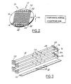
- the preferred antenna 10 is illustrated in Figures 2 through 4 and provides a low cost and low profile configuration that also provides high performance. It should be understood that the illustrated antenna configuration is merely a preferred embodiment for achieving the objects of the present invention and that other configurations that provide low cost, low profile, and high performance may be utilized.
- the antenna 10 includes a plurality of antenna radiation elements 14 that are positioned on a circular plate 16.
- the circular plate 16 is a rotating plate that rotates about a center axis, as will be described further herein.
- the rotating plate 16 is less than one inch (1") thick and has a diameter of fifteen inches (15") or less. Obviously, the dimensions of the rotating plate 16 may vary. However, the greater the diameter and thickness, the larger and more costly the antenna 10 will become.
- the antenna radiation elements 14 are preferably constructed using a plurality of parallel slotted waveguides 18. However, a variety of different antenna radiation elements may instead be utilized, such as patch arrays. The operation of the disclosed antenna configuration is described in a receive mode only. The corresponding transmission mode operation can be easily understood by one of skill in the art via reciprocity.
- each slotted waveguide element 18 is approximately 10 wavelengths long.
- 16 long waveguide elements 18 are positioned on the circular plate 16.
- the waveguide elements 18 are grouped into two groups and are interlaced, as shown in Figure 2, such that waveguide la and waveguide lb begin at opposite ends of the circular plate 16 and overlap one another.
- Each of the individual waveguides are preferably separated by one-half wavelength (1 ⁇ 2 ⁇ ). Therefore, the total aperture in which the waveguide elements are positioned is about 10 x 10 wavelength in a square and the expected peak gain of a straight out or boresight beam from this aperture is about 28 to 30 dB.
- the circular plate 16 rotates, rotating the antenna radiation elements 14 therewith, the vertical position of the circular plate 16 remains generally stationary.
- the number of waveguides positioned on the circular plate may vary, however, the preferred number of waveguide elements is between 10 and 20. Further, the distance between the waveguide elements and their length may also vary.
- the array antenna 10 In a receive mode, the array antenna 10 will be rotated in the azimuth such that all slot array elements 18 will be in alignment with the planar wavefront of an intended incoming signal. Consequently, all the slots in a long waveguide element 18 are excited by the same planar wavefront simultaneously.
- Each slotted waveguide element 18 has a first end 20 and a second end 22.
- the first ends 20 are positioned on a surface of the aperture 24 defining the radiation elements, while the second ends 22 are overlapped by adjacent slotted waveguide elements 18 such that the elements are interdigitally spaced.
- Each waveguide element 18 has a plurality of cross-slot openings 26 formed on their top surfaces 28.
- An H-plane septum (a metal plate) 30 is inserted into each waveguide element 18.
- Each metal plate 30 has a plurality of slanted slots 32 formed therethrough which act as one of the key circular polarization exciting mechanisms.
- the waveguide elements 18 operate in a standing wave mode and have an identical fan-beam pattern with a 6° by 150° elliptical beam created through the cross-slot openings 26 on the top surfaces 28 of the waveguides 18.
- the cross-slotted waveguides 18 and the septum plate 30 are both illustrated in Figure 4.
- the slanted slots 32 on the septum plate 30 are angled at approximately 45° and when positioned inside each waveguide element 18 will interact with the matching perpendicular cross-slots 26 on the top surface 28 (or E-plane) of the respective waveguide element 18.
- an incoming (right-hand) circular polarized wave on the E-plane wall will excite an TE 01 mode wave inside each waveguide element 18.
- the slant angle of the slanted slots 32 on the septum 30 must change to approximately 135° or 45° in the opposite direction.
- some of the longitudinal elements 18 will have septums 30 with slanted slots 32 at approximately 45° and some of elements 18 will have septums 30 with slanted slots 32 at approximately 135°. It should be understood that a variety of other types of waveguide elements may be utilized so long as they allow for the formation of multiple beams.
- the circular plate 16 will be rotated to a position such that the wave front of an intended incoming wave is parallel to the central axes of these slotted waveguide 18.
- the fan beam radiation pattern of each slotted waveguide element 18 will intercept the incoming wave individually, which will then be amplified, filtered, coded, multiplexed, and down converted.
- the conditioned signals will be converted to digital streams, which will then be decoded, digital beamformed, and then transferred to a digital receiver.
- a digital receiver will then convert the received waveform into information signals.
- each of the pair of sixteen slotted waveguides 18 will individually intercept an incoming wave.
- the waves will be intercepted by the phased array elements 18.
- the top portion of Figure 5 is a schematic of a Ku band receive array. Similar architectures can be utilized for other frequency bands, such as L-band, S-band, and Ka band. Obviously, the present invention may be utilized for each of these frequency bands.
- the waves received at the waveguide elements 18 are processed by circuitry associated with each of the elements.
- the incoming wave is then amplified by a respective linear amplifier 38 before being passed to a conventional band pass filter 40 where the signal is filtered.
- the signal After the signal has been filtered, it is then coded at a code generator 42 before being transferred to a multiplexer 44.
- the multiplexed signal is passed to an amplifier 46 before being multiplexed and then converted to a digital stream 48 by an analog-to-digital converter 50.
- the code division multiplex technique illustrated in the top portion of Figure 4 reduces the number of components in the down conversion chain as well as the number of analog-to-digital converters.
- the received signals from the waveguide elements 18 are multiplexed at the multiplexer 44 into a single microwave stream by known CDMA techniques, such as disclosed in U.S. Patent No. 5,077,562.
- the multiplexing of the multiple signals reduces the number of components necessary to process the signals and consequently reduces the cost of the ground terminals.
- the receiver dynamic range can also be significantly enhanced through the oversampling of the analog to digital converter.
- the entire receiving antenna processing is performed through the combination of low profile one dimension radiation elements 14, which are placed in parallel on the circular rotating plate 16.
- the processing is further accompanied by aligning the long radiating elements 14 along the intended incoming waveform by rotating the circular plate 16 and then performing beam forming in the orthogonal direction by summing up the output signals of the long radiation elements.
- a high performance antenna can be provided with a very low profile circular volume.
- Figure 5 illustrates a retrodirective mechanism that is integrated into the low profile antenna 10, described above, to eliminate the cost of conventional tracking mechanisms, in accordance with another preferred embodiment of the present invention.
- the output of the analog-to-digital converter 48 is then input into a plurality of match filters 52, whose outputs are transferred to a digital multibeam beamforming device 54.
- the digital beams 56 are then transferred to a respective code generator 58 before being multiplexed at a multiplexer 60.
- the multiplexed beam 62 is then transferred to a digital receiver 64 where the received waveforms are converted into information signals 66.
- the entire receiving antenna and tracking processing of this preferred embodiment is through the low profile, one dimensional radiation elements 14.
- the radiation elements 14 are again preferably placed in parallel on the circular plate 16 which rotates about its center axis.
- the long radiation elements 16 are also aligned along the intended incoming waveform by the rotating circular plate 16 and then subjected to multiple beamforming through fast fourier transforms (FFT) at the digital multibeam beamforming device 54.
- FFT fast fourier transforms
- the outputs of the digital multibeam beamforming device 54 through FFT are associated with signals from various directions covered by the different (contiguous) beams.
- the outputs of the FFT will be fed into a retrodirective processing mechanism, as described below, to determine where the intended signal is coming from and then to send the transmit signal to the same direction.
- the low cost tracking is accomplished by retrodirectivity.
- the history of the beam positioning will be stored in the terminal as a reference for the satellite emphamerie.
- the received signals are again multiplexed into a single microwave stream via known CDMA techniques to reduce the component counts and the ultimate cost of the ground terminals.
- Incorporating the unique multiple digital beam forming technique with multiplexing provides contiguous multiple receive beams.
- the receiver monitors the signals from all the multiple beams simultaneously.
- the outputs of the digital multiple beamformer are then indexed through a set of orthogonal codes, such as hadema code, each of which represents the unique beam direction. By identifying the code of the signals locked onto the receiver, the location where the signal is coming from has been identified as well as the corresponding phase slope of the received aperture.
- the transmit signal will be directed to the same antenna beam position from where the received signal originated.
- the transmit beam can then be steered by a phase conjunction mechanism.
- This multibeam beamforming and phase conjugation mechanism using a Bulter matrix is described in U.S. Patent No. 4,812,788. However, the present mechanism is incorporated in digital form through FFT and is therefore uniquely different from a Bulter matrix.
- the transmit beam utilizes the phasing information, to perform a phase conjugation across the array element, and digitally multiply the outgoing signals with the conjugated phasing (equivalently perform a DFT to the signals on the array aperture). All the retrodirective functions can be accomplished in a very low power and low cost consumer digital electronics.
- the tracking mechanism is similar to that of a step scan principle.
- the signal strengths from adjacent received beams will be monitored and used to compare with the one coming from the main beam, the beam with the strongest signal will be identified as the locked (main) beam.
- a user terminal within the field of view (FOV) will switch the antenna to receive, and transmit beams from one position to another accordingly without conventional antenna tracking loops.
- the disclosed terminal can use the disclosed terminal to avoid interruption during handover.
- the disclosed antenna can form two beams pointed towards these two satellites simultaneously. Consequently, it can provide the capability of "connect before break" during the hand over phase.
- This low profile antenna configuration with a low profile randome may look like a thick pizza, and can be mounted on top of a moving vehicle, such as an automobile or an aircraft.
- This configuration can also be used as fixed user or mobile terminals for low_earth orbit satellite constellations at L, S, Ku, and Ka frequency bands.
Landscapes
- Engineering & Computer Science (AREA)
- Physics & Mathematics (AREA)
- Astronomy & Astrophysics (AREA)
- Aviation & Aerospace Engineering (AREA)
- General Physics & Mathematics (AREA)
- Computer Networks & Wireless Communication (AREA)
- Signal Processing (AREA)
- Remote Sensing (AREA)
- Variable-Direction Aerials And Aerial Arrays (AREA)
Applications Claiming Priority (2)
| Application Number | Priority Date | Filing Date | Title |
|---|---|---|---|
| US09/497,865 US7339520B2 (en) | 2000-02-04 | 2000-02-04 | Phased array terminal for equatorial satellite constellations |
| US497865 | 2000-02-04 |
Publications (3)
| Publication Number | Publication Date |
|---|---|
| EP1122813A2 true EP1122813A2 (fr) | 2001-08-08 |
| EP1122813A3 EP1122813A3 (fr) | 2004-03-10 |
| EP1122813B1 EP1122813B1 (fr) | 2007-11-28 |
Family
ID=23978620
Family Applications (1)
| Application Number | Title | Priority Date | Filing Date |
|---|---|---|---|
| EP01101660A Expired - Lifetime EP1122813B1 (fr) | 2000-02-04 | 2001-01-29 | Terminal à réseau d'antennes à commande de phase pour constellations de satellites équatoriales |
Country Status (4)
| Country | Link |
|---|---|
| US (1) | US7339520B2 (fr) |
| EP (1) | EP1122813B1 (fr) |
| CA (1) | CA2330990C (fr) |
| DE (1) | DE60131581T2 (fr) |
Cited By (14)
| Publication number | Priority date | Publication date | Assignee | Title |
|---|---|---|---|---|
| US6781555B2 (en) | 2000-10-31 | 2004-08-24 | The Directv Group, Inc. | Multi-beam antenna communication system and method |
| US6941138B1 (en) | 2000-09-05 | 2005-09-06 | The Directv Group, Inc. | Concurrent communications between a user terminal and multiple stratospheric transponder platforms |
| US6952580B2 (en) | 2000-12-12 | 2005-10-04 | The Directv Group, Inc. | Multiple link internet protocol mobile communications system and method therefor |
| US7103317B2 (en) | 2000-12-12 | 2006-09-05 | The Directv Group, Inc. | Communication system using multiple link terminals for aircraft |
| US7181162B2 (en) | 2000-12-12 | 2007-02-20 | The Directv Group, Inc. | Communication system using multiple link terminals |
| US7187949B2 (en) | 2001-01-19 | 2007-03-06 | The Directv Group, Inc. | Multiple basestation communication system having adaptive antennas |
| WO2009144763A1 (fr) | 2008-05-29 | 2009-12-03 | Rf Microtech S.R.L. | Antenne plate à balayage |
| US7809403B2 (en) | 2001-01-19 | 2010-10-05 | The Directv Group, Inc. | Stratospheric platforms communication system using adaptive antennas |
| US8396513B2 (en) | 2001-01-19 | 2013-03-12 | The Directv Group, Inc. | Communication system for mobile users using adaptive antenna |
| US9391631B1 (en) | 2015-01-27 | 2016-07-12 | Raytheon Company | Processing system with encoding for processing multiple analog signals |
| WO2017151790A1 (fr) * | 2016-03-01 | 2017-09-08 | Kymeta Corporation | Acquisition et suivi de signal satellite par antenne mobile |
| US10811784B2 (en) | 2016-03-01 | 2020-10-20 | Kymeta Corporation | Broadband RF radial waveguide feed with integrated glass transition |
| US10884094B2 (en) | 2016-03-01 | 2021-01-05 | Kymeta Corporation | Acquiring and tracking a satellite signal with a scanned antenna |
| US11710887B2 (en) | 2018-05-31 | 2023-07-25 | Kymeta Corporation | Satellite signal acquisition |
Families Citing this family (34)
| Publication number | Priority date | Publication date | Assignee | Title |
|---|---|---|---|---|
| US6388615B1 (en) * | 2000-06-06 | 2002-05-14 | Hughes Electronics Corporation | Micro cell architecture for mobile user tracking communication system |
| US6763242B1 (en) | 2000-09-14 | 2004-07-13 | The Directv Group, Inc. | Resource assignment system and method for determining the same |
| US6891813B2 (en) * | 2000-12-12 | 2005-05-10 | The Directv Group, Inc. | Dynamic cell CDMA code assignment system and method |
| US7400857B2 (en) * | 2000-12-12 | 2008-07-15 | The Directv Group, Inc. | Communication system using multiple link terminals |
| DE60213843D1 (de) * | 2001-11-09 | 2006-09-21 | Ems Technologies Inc | Strahlformer für eine mehrkeulenempfangsantenne |
| US7379707B2 (en) * | 2004-08-26 | 2008-05-27 | Raysat Antenna Systems, L.L.C. | System for concurrent mobile two-way data communications and TV reception |
| US7705793B2 (en) * | 2004-06-10 | 2010-04-27 | Raysat Antenna Systems | Applications for low profile two way satellite antenna system |
| US8761663B2 (en) * | 2004-01-07 | 2014-06-24 | Gilat Satellite Networks, Ltd | Antenna system |
| US20110215985A1 (en) * | 2004-06-10 | 2011-09-08 | Raysat Antenna Systems, L.L.C. | Applications for Low Profile Two Way Satellite Antenna System |
| US7911400B2 (en) * | 2004-01-07 | 2011-03-22 | Raysat Antenna Systems, L.L.C. | Applications for low profile two-way satellite antenna system |
| US20060227048A1 (en) * | 2004-12-20 | 2006-10-12 | Ems Technologies, Inc. | Electronic pitch over mechanical roll antenna |
| DE602006013994D1 (de) * | 2005-08-09 | 2010-06-10 | Atc Tech Llc | Satellitenkommunikationssysteme und verfahren mit verwendung von im wesentlichen benachbarten funkverbindungsantennen |
| US7498994B2 (en) * | 2006-09-26 | 2009-03-03 | Honeywell International Inc. | Dual band antenna aperature for millimeter wave synthetic vision systems |
| US9435893B2 (en) | 2007-05-21 | 2016-09-06 | Spatial Digital Systems, Inc. | Digital beam-forming apparatus and technique for a multi-beam global positioning system (GPS) receiver |
| US7924223B1 (en) | 2007-12-06 | 2011-04-12 | Chang Donald C D | Satellite ground terminal incorporating a smart antenna that rejects interference |
| US9077427B2 (en) * | 2009-07-30 | 2015-07-07 | Spatial Digital Systems, Inc. | Coherent power combining via wavefront multiplexing on deep space spacecraft |
| US10149298B2 (en) | 2009-07-30 | 2018-12-04 | Spatial Digital Systems, Inc. | Dynamic power allocations for direct broadcasting satellite (DBS) channels via wavefront multiplexing |
| US8111646B1 (en) | 2009-07-30 | 2012-02-07 | Chang Donald C D | Communication system for dynamically combining power from a plurality of propagation channels in order to improve power levels of transmitted signals without affecting receiver and propagation segments |
| US8526985B2 (en) * | 2009-11-30 | 2013-09-03 | Alcatel Lucent | System and method of geo-concentrated video detection |
| US20110197740A1 (en) * | 2010-02-16 | 2011-08-18 | Chang Donald C D | Novel Karaoke and Multi-Channel Data Recording / Transmission Techniques via Wavefront Multiplexing and Demultiplexing |
| JPWO2011145264A1 (ja) * | 2010-05-21 | 2013-07-22 | 日本電気株式会社 | アンテナ装置、アンテナシステム、及びその調整方法 |
| US9100085B2 (en) * | 2011-09-21 | 2015-08-04 | Spatial Digital Systems, Inc. | High speed multi-mode fiber transmissions via orthogonal wavefronts |
| EP2611043A1 (fr) | 2011-12-29 | 2013-07-03 | Spatial Digital Systems, Inc. | Système de communication pour combiner dynamiquement l'énergie de plusieurs canaux de propagation afin d'améliorer les niveaux d'énergie de signaux transmis sans affecter le récepteur et les segments de propagation |
| KR102079350B1 (ko) | 2013-03-20 | 2020-02-19 | 삼성전자주식회사 | 캐리어 어그리게이션 처리 장치와 회로 |
| US9466869B2 (en) * | 2013-09-06 | 2016-10-11 | Empire Technoogy Development Llc | Optimal direction determination of radio signals |
| CN105579865B (zh) * | 2013-09-27 | 2018-10-26 | 日产自动车株式会社 | 天线装置以及信号处理方法 |
| US10104661B2 (en) | 2014-01-22 | 2018-10-16 | Empire Technology Development Llc | Adaptively selecting from among multiple base stations |
| US9819082B2 (en) | 2014-11-03 | 2017-11-14 | Northrop Grumman Systems Corporation | Hybrid electronic/mechanical scanning array antenna |
| US10396444B2 (en) | 2016-05-11 | 2019-08-27 | Panasonic Avionics Corporation | Antenna assembly |
| US10439275B2 (en) | 2016-06-24 | 2019-10-08 | Ford Global Technologies, Llc | Multiple orientation antenna for vehicle communication |
| RU2701460C1 (ru) * | 2018-06-05 | 2019-09-26 | Геннадий Петрович Слукин | Способ формирования приемных парциальных лучей для параллельного обзора пространства |
| US11063661B2 (en) * | 2018-06-06 | 2021-07-13 | Kymeta Corporation | Beam splitting hand off systems architecture |
| US10553940B1 (en) | 2018-08-30 | 2020-02-04 | Viasat, Inc. | Antenna array with independently rotated radiating elements |
| US11233325B2 (en) | 2020-02-07 | 2022-01-25 | Panasonic Avionics Corporation | Antenna assembly |
Family Cites Families (63)
| Publication number | Priority date | Publication date | Assignee | Title |
|---|---|---|---|---|
| US3541553A (en) * | 1968-03-27 | 1970-11-17 | Rca Corp | Satellite communications systems |
| US3673606A (en) | 1969-08-26 | 1972-06-27 | Hazeltine Corp | Flush mounted steerable array antenna |
| US3720953A (en) * | 1972-02-02 | 1973-03-13 | Hughes Aircraft Co | Dual polarized slot elements in septated waveguide cavity |
| US4799065A (en) * | 1983-03-17 | 1989-01-17 | Hughes Aircraft Company | Reconfigurable beam antenna |
| US4635063A (en) * | 1983-05-06 | 1987-01-06 | Hughes Aircraft Company | Adaptive antenna |
| GB2170959A (en) | 1985-02-07 | 1986-08-13 | Nat Res Dev | Slotted waveguide antennas and arrays |
| US5257030A (en) * | 1987-09-22 | 1993-10-26 | Mitsubishi Denki Kabushiki Kaisha | Antenna system |
| US4812788A (en) * | 1987-11-02 | 1989-03-14 | Hughes Aircraft Company | Waveguide matrix including in-plane crossover |
| US4979170A (en) * | 1988-01-19 | 1990-12-18 | Qualcomm, Inc. | Alternating sequential half duplex communication system |
| US4926186A (en) | 1989-03-20 | 1990-05-15 | Allied-Signal Inc. | FFT-based aperture monitor for scanning phased arrays |
| US5017927A (en) * | 1990-02-20 | 1991-05-21 | General Electric Company | Monopulse phased array antenna with plural transmit-receive module phase shifters |
| US5081464A (en) * | 1990-07-12 | 1992-01-14 | Hughes Aircraft Company | Method and apparatus for producing multiple, frequency-addressable scanning beams |
| US5218619A (en) * | 1990-12-17 | 1993-06-08 | Ericsson Ge Mobile Communications Holding, Inc. | CDMA subtractive demodulation |
| US5077562A (en) * | 1990-12-24 | 1991-12-31 | Hughes Aircraft Company | Digital beam-forming technique using temporary noise injection |
| FR2672436B1 (fr) * | 1991-01-31 | 1993-09-10 | Europ Agence Spatiale | Dispositif de controle electronique du diagramme de rayonnement d'une antenne a un ou plusieurs faisceaux de direction et/ou de largeur variable. |
| US5387916A (en) * | 1992-07-31 | 1995-02-07 | Westinghouse Electric Corporation | Automotive navigation system and method |
| US5379320A (en) * | 1993-03-11 | 1995-01-03 | Southern California Edison Company | Hitless ultra small aperture terminal satellite communication network |
| JP3364295B2 (ja) | 1993-10-08 | 2003-01-08 | 株式会社日立国際電気 | 衛星放送受信用平面アレーアンテナ |
| US6020845A (en) * | 1993-11-19 | 2000-02-01 | Stanford Telecommunications, Inc. | Satellite for increasing the utility of satellite communication systems |
| US5572216A (en) * | 1993-11-19 | 1996-11-05 | Stanford Telecommunications, Inc. | System for increasing the utility of satellite communication systems |
| US5589834A (en) * | 1994-04-22 | 1996-12-31 | Stanford Telecommunications, Inc. | Cost effective geosynchronous mobile satellite communication system |
| GB2293725B (en) * | 1994-07-22 | 1999-02-10 | Int Maritime Satellite Organiz | Satellite communication method and apparatus |
| US5552798A (en) * | 1994-08-23 | 1996-09-03 | Globalstar L.P. | Antenna for multipath satellite communication links |
| US5684491A (en) * | 1995-01-27 | 1997-11-04 | Hazeltine Corporation | High gain antenna systems for cellular use |
| FR2737627B1 (fr) * | 1995-08-02 | 1997-10-03 | Europ Agence Spatiale | Systeme de transmission de signaux radioelectriques via un satellite de communication geostationnaire, notamment pour des communications avec des terminaux mobiles portables |
| AU6709396A (en) | 1995-08-11 | 1997-03-12 | Ramot University Authority For Applied Research And Industrial Development Ltd. | High altitude cellular communication system platform |
| US5909460A (en) * | 1995-12-07 | 1999-06-01 | Ericsson, Inc. | Efficient apparatus for simultaneous modulation and digital beamforming for an antenna array |
| CA2217730A1 (fr) | 1996-03-08 | 1997-09-12 | Makoto Ochiai | Antenne reseau plan |
| US5917447A (en) * | 1996-05-29 | 1999-06-29 | Motorola, Inc. | Method and system for digital beam forming |
| US6259415B1 (en) * | 1996-06-03 | 2001-07-10 | Bae Systems Advanced Systems | Minimum protrusion mechanically beam steered aircraft array antenna systems |
| US5754139A (en) * | 1996-10-30 | 1998-05-19 | Motorola, Inc. | Method and intelligent digital beam forming system responsive to traffic demand |
| US5856804A (en) * | 1996-10-30 | 1999-01-05 | Motorola, Inc. | Method and intelligent digital beam forming system with improved signal quality communications |
| US6151308A (en) * | 1996-12-30 | 2000-11-21 | Motorola, Inc. | Elevated communication hub and method of operation therefor |
| US5764187A (en) * | 1997-01-21 | 1998-06-09 | Ail Systems, Inc. | Direct digital synthesizer driven phased array antenna |
| US6018316A (en) * | 1997-01-24 | 2000-01-25 | Ail Systems, Inc. | Multiple beam antenna system and method |
| US5903549A (en) * | 1997-02-21 | 1999-05-11 | Hughes Electronics Corporation | Ground based beam forming utilizing synchronized code division multiplexing |
| US6016124A (en) * | 1997-04-07 | 2000-01-18 | Nortel Networks Corporation | Digital beamforming in a satellite communication system |
| US5990928A (en) * | 1997-05-30 | 1999-11-23 | Rockwell International Corporation | Method and apparatus for receiving broadcast entertainment transmissions at a moving receiver station |
| KR100312836B1 (ko) | 1997-06-03 | 2001-12-28 | 다치카와 게이지 | 어댑티브어레이송수신기 |
| US5973647A (en) * | 1997-09-17 | 1999-10-26 | Aerosat Corporation | Low-height, low-cost, high-gain antenna and system for mobile platforms |
| US6434384B1 (en) * | 1997-10-17 | 2002-08-13 | The Boeing Company | Non-uniform multi-beam satellite communications system and method |
| US6061562A (en) * | 1997-10-30 | 2000-05-09 | Raytheon Company | Wireless communication using an airborne switching node |
| US6014372A (en) * | 1997-12-08 | 2000-01-11 | Lockheed Martin Corp. | Antenna beam congruency system for spacecraft cellular communications system |
| US6173178B1 (en) * | 1997-12-16 | 2001-01-09 | Trw Inc. | Satellite beam pattern for non-uniform population distribution |
| US5982337A (en) * | 1998-02-20 | 1999-11-09 | Marconi Aerospace Systems Inc. | Cellular antennas for stratosphere coverage of multi-band annular earth pattern |
| US6111542A (en) * | 1998-04-06 | 2000-08-29 | Motorola, Inc. | Rotating electronically steerable antenna system and method of operation thereof |
| WO1999060656A2 (fr) * | 1998-05-20 | 1999-11-25 | L-3 Communications Essco, Inc. | Antenne de communication par satellite a faisceaux multiples |
| JP3316561B2 (ja) * | 1998-07-06 | 2002-08-19 | 株式会社村田製作所 | アレーアンテナ装置および無線装置 |
| US6208858B1 (en) * | 1998-07-21 | 2001-03-27 | Qualcomm Incorporated | System and method for reducing call dropping rates in a multi-beam communication system |
| US6151496A (en) * | 1998-10-22 | 2000-11-21 | Raytheon Company | System and method of performing soft hand-off with one-dimensional AESA |
| US6266528B1 (en) * | 1998-12-23 | 2001-07-24 | Arraycomm, Inc. | Performance monitor for antenna arrays |
| US6400925B1 (en) * | 1999-02-25 | 2002-06-04 | Trw Inc. | Packet switch control with layered software |
| US6204823B1 (en) * | 1999-03-09 | 2001-03-20 | Harris Corporation | Low profile antenna positioner for adjusting elevation and azimuth |
| GB2349045A (en) | 1999-04-16 | 2000-10-18 | Fujitsu Ltd | Base station transmission beam pattern forming; interference reduction |
| US6198455B1 (en) * | 2000-03-21 | 2001-03-06 | Space Systems/Loral, Inc. | Variable beamwidth antenna systems |
| JP3424659B2 (ja) | 2000-06-02 | 2003-07-07 | 日本電気株式会社 | マルチビーム受信装置 |
| US6388615B1 (en) * | 2000-06-06 | 2002-05-14 | Hughes Electronics Corporation | Micro cell architecture for mobile user tracking communication system |
| US6429823B1 (en) * | 2000-08-11 | 2002-08-06 | Hughes Electronics Corporation | Horn reflect array |
| US6380893B1 (en) * | 2000-09-05 | 2002-04-30 | Hughes Electronics Corporation | Ground-based, wavefront-projection beamformer for a stratospheric communications platform |
| US6366256B1 (en) * | 2000-09-20 | 2002-04-02 | Hughes Electronics Corporation | Multi-beam reflector antenna system with a simple beamforming network |
| US6388634B1 (en) * | 2000-10-31 | 2002-05-14 | Hughes Electronics Corporation | Multi-beam antenna communication system and method |
| US7068733B2 (en) * | 2001-02-05 | 2006-06-27 | The Directv Group, Inc. | Sampling technique for digital beam former |
| US6559797B1 (en) * | 2001-02-05 | 2003-05-06 | Hughes Electronics Corporation | Overlapping subarray patch antenna system |
-
2000
- 2000-02-04 US US09/497,865 patent/US7339520B2/en not_active Expired - Fee Related
-
2001
- 2001-01-15 CA CA002330990A patent/CA2330990C/fr not_active Expired - Fee Related
- 2001-01-29 DE DE60131581T patent/DE60131581T2/de not_active Expired - Lifetime
- 2001-01-29 EP EP01101660A patent/EP1122813B1/fr not_active Expired - Lifetime
Cited By (17)
| Publication number | Priority date | Publication date | Assignee | Title |
|---|---|---|---|---|
| US6941138B1 (en) | 2000-09-05 | 2005-09-06 | The Directv Group, Inc. | Concurrent communications between a user terminal and multiple stratospheric transponder platforms |
| US6781555B2 (en) | 2000-10-31 | 2004-08-24 | The Directv Group, Inc. | Multi-beam antenna communication system and method |
| US6952580B2 (en) | 2000-12-12 | 2005-10-04 | The Directv Group, Inc. | Multiple link internet protocol mobile communications system and method therefor |
| US7103317B2 (en) | 2000-12-12 | 2006-09-05 | The Directv Group, Inc. | Communication system using multiple link terminals for aircraft |
| US7181162B2 (en) | 2000-12-12 | 2007-02-20 | The Directv Group, Inc. | Communication system using multiple link terminals |
| US8396513B2 (en) | 2001-01-19 | 2013-03-12 | The Directv Group, Inc. | Communication system for mobile users using adaptive antenna |
| US7809403B2 (en) | 2001-01-19 | 2010-10-05 | The Directv Group, Inc. | Stratospheric platforms communication system using adaptive antennas |
| US7187949B2 (en) | 2001-01-19 | 2007-03-06 | The Directv Group, Inc. | Multiple basestation communication system having adaptive antennas |
| WO2009144763A1 (fr) | 2008-05-29 | 2009-12-03 | Rf Microtech S.R.L. | Antenne plate à balayage |
| US9391631B1 (en) | 2015-01-27 | 2016-07-12 | Raytheon Company | Processing system with encoding for processing multiple analog signals |
| WO2016122768A1 (fr) * | 2015-01-27 | 2016-08-04 | Raytheon Company | Procédé et circuits pour convertir des signaux analogiques en des signaux numériques |
| WO2017151790A1 (fr) * | 2016-03-01 | 2017-09-08 | Kymeta Corporation | Acquisition et suivi de signal satellite par antenne mobile |
| IL261336A (en) * | 2016-03-01 | 2018-10-31 | Kymeta Corp | Acquiring and tracking a satellite signal with a mobile antenna |
| US10811784B2 (en) | 2016-03-01 | 2020-10-20 | Kymeta Corporation | Broadband RF radial waveguide feed with integrated glass transition |
| US10884094B2 (en) | 2016-03-01 | 2021-01-05 | Kymeta Corporation | Acquiring and tracking a satellite signal with a scanned antenna |
| EP4564041A3 (fr) * | 2016-03-01 | 2025-08-20 | Kymeta Corporation | Acquisition et poursuite d'un signal satellite avec une antenne mobile |
| US11710887B2 (en) | 2018-05-31 | 2023-07-25 | Kymeta Corporation | Satellite signal acquisition |
Also Published As
| Publication number | Publication date |
|---|---|
| EP1122813B1 (fr) | 2007-11-28 |
| DE60131581T2 (de) | 2008-07-10 |
| DE60131581D1 (de) | 2008-01-10 |
| EP1122813A3 (fr) | 2004-03-10 |
| CA2330990A1 (fr) | 2001-08-04 |
| US20020050946A1 (en) | 2002-05-02 |
| CA2330990C (fr) | 2003-11-04 |
| US7339520B2 (en) | 2008-03-04 |
Similar Documents
| Publication | Publication Date | Title |
|---|---|---|
| EP1122813B1 (fr) | Terminal à réseau d'antennes à commande de phase pour constellations de satellites équatoriales | |
| US9287961B2 (en) | Receive only smart ground-terminal antenna for geostationary satellites in slightly inclined orbits | |
| US5838282A (en) | Multi-frequency antenna | |
| EP0907983B1 (fr) | Antenne reseau plane bifrequence | |
| US8604989B1 (en) | Steerable antenna | |
| US3340531A (en) | Satellite communication system | |
| US20020167449A1 (en) | Low profile phased array antenna | |
| US6208312B1 (en) | Multi-feed multi-band antenna | |
| US20210313687A1 (en) | Radio transceiver with antenna array formed by horn-antenna elements | |
| US20020073437A1 (en) | Television distribution system using multiple links | |
| US6049305A (en) | Compact antenna for low and medium earth orbit satellite communication systems | |
| Ricardi | Communication satellite antennas | |
| Abdel-Wahab et al. | Affordable large scale active-phased array antenna for Ka-band mobile SATCOM applications | |
| US6825815B1 (en) | Steerable uplink antenna for moveable redundant beams | |
| Gao et al. | Guest editorial: Antennas for satellite communications | |
| KR100682984B1 (ko) | 다중대역 하이브리드 안테나 시스템 | |
| EP1184940A2 (fr) | Réseaux d'antennes à techniques rayonnantes indirects | |
| Woo et al. | Performance of a family of omni and steered antennas for mobile satellite applications | |
| Kobayashi | A novel butler matrix based beam forming network architecture for multiple antenna beam steering | |
| US20240413532A1 (en) | Nested concentric coaxial feed assembly for ground antennas supporting multiple frequency bands | |
| US5995056A (en) | Wide band tem fed phased array reflector antenna | |
| Bialkowski et al. | Fixed and Mobile Antennas for Satellite Communications | |
| Maddocks et al. | Flat-plate steerable antennas for satellite communications and broadcast reception | |
| Hirosawa et al. | S/X/Ka-band/spl phi/34m beam-waveguide-fed antenna for telemetry, tracking and control of scientific satellite | |
| Hirosawa et al. | S/X/KA-BAND Φ34M ANTENNA BY BEAM-WAVEGUIDE-FEED FOR TELEMETRY, TRACKING AND CONTROL OF SCIENTIFIC SATELLITE |
Legal Events
| Date | Code | Title | Description |
|---|---|---|---|
| PUAI | Public reference made under article 153(3) epc to a published international application that has entered the european phase |
Free format text: ORIGINAL CODE: 0009012 |
|
| AK | Designated contracting states |
Kind code of ref document: A2 Designated state(s): AT BE CH CY DE DK ES FI FR GB GR IE IT LI LU MC NL PT SE TR |
|
| AX | Request for extension of the european patent |
Free format text: AL;LT;LV;MK;RO;SI |
|
| PUAL | Search report despatched |
Free format text: ORIGINAL CODE: 0009013 |
|
| AK | Designated contracting states |
Kind code of ref document: A3 Designated state(s): AT BE CH CY DE DK ES FI FR GB GR IE IT LI LU MC NL PT SE TR |
|
| AX | Request for extension of the european patent |
Extension state: AL LT LV MK RO SI |
|
| RIC1 | Information provided on ipc code assigned before grant |
Ipc: 7H 01Q 3/04 A Ipc: 7H 01Q 21/00 B Ipc: 7H 01Q 1/32 B Ipc: 7H 01Q 3/26 B Ipc: 7H 01Q 13/22 B |
|
| 17P | Request for examination filed |
Effective date: 20040907 |
|
| AKX | Designation fees paid |
Designated state(s): DE FR GB SE |
|
| 17Q | First examination report despatched |
Effective date: 20050125 |
|
| GRAP | Despatch of communication of intention to grant a patent |
Free format text: ORIGINAL CODE: EPIDOSNIGR1 |
|
| GRAS | Grant fee paid |
Free format text: ORIGINAL CODE: EPIDOSNIGR3 |
|
| GRAA | (expected) grant |
Free format text: ORIGINAL CODE: 0009210 |
|
| AK | Designated contracting states |
Kind code of ref document: B1 Designated state(s): DE FR GB SE |
|
| REG | Reference to a national code |
Ref country code: GB Ref legal event code: FG4D |
|
| REF | Corresponds to: |
Ref document number: 60131581 Country of ref document: DE Date of ref document: 20080110 Kind code of ref document: P |
|
| REG | Reference to a national code |
Ref country code: SE Ref legal event code: TRGR |
|
| ET | Fr: translation filed | ||
| PLBE | No opposition filed within time limit |
Free format text: ORIGINAL CODE: 0009261 |
|
| STAA | Information on the status of an ep patent application or granted ep patent |
Free format text: STATUS: NO OPPOSITION FILED WITHIN TIME LIMIT |
|
| 26N | No opposition filed |
Effective date: 20080829 |
|
| REG | Reference to a national code |
Ref country code: FR Ref legal event code: PLFP Year of fee payment: 16 |
|
| REG | Reference to a national code |
Ref country code: FR Ref legal event code: PLFP Year of fee payment: 17 |
|
| PGFP | Annual fee paid to national office [announced via postgrant information from national office to epo] |
Ref country code: GB Payment date: 20161228 Year of fee payment: 17 |
|
| PGFP | Annual fee paid to national office [announced via postgrant information from national office to epo] |
Ref country code: FR Payment date: 20170103 Year of fee payment: 17 Ref country code: DE Payment date: 20170131 Year of fee payment: 17 Ref country code: SE Payment date: 20170109 Year of fee payment: 17 |
|
| REG | Reference to a national code |
Ref country code: DE Ref legal event code: R119 Ref document number: 60131581 Country of ref document: DE |
|
| REG | Reference to a national code |
Ref country code: SE Ref legal event code: EUG |
|
| GBPC | Gb: european patent ceased through non-payment of renewal fee |
Effective date: 20180129 |
|
| PG25 | Lapsed in a contracting state [announced via postgrant information from national office to epo] |
Ref country code: FR Free format text: LAPSE BECAUSE OF NON-PAYMENT OF DUE FEES Effective date: 20180131 Ref country code: DE Free format text: LAPSE BECAUSE OF NON-PAYMENT OF DUE FEES Effective date: 20180801 Ref country code: SE Free format text: LAPSE BECAUSE OF NON-PAYMENT OF DUE FEES Effective date: 20180130 |
|
| REG | Reference to a national code |
Ref country code: FR Ref legal event code: ST Effective date: 20180928 |
|
| PG25 | Lapsed in a contracting state [announced via postgrant information from national office to epo] |
Ref country code: GB Free format text: LAPSE BECAUSE OF NON-PAYMENT OF DUE FEES Effective date: 20180129 |