EP1122832A2 - Kontaktbuchse - Google Patents
Kontaktbuchse Download PDFInfo
- Publication number
- EP1122832A2 EP1122832A2 EP01300886A EP01300886A EP1122832A2 EP 1122832 A2 EP1122832 A2 EP 1122832A2 EP 01300886 A EP01300886 A EP 01300886A EP 01300886 A EP01300886 A EP 01300886A EP 1122832 A2 EP1122832 A2 EP 1122832A2
- Authority
- EP
- European Patent Office
- Prior art keywords
- contact
- spring
- engagement sleeve
- socket according
- sleeve
- Prior art date
- Legal status (The legal status is an assumption and is not a legal conclusion. Google has not performed a legal analysis and makes no representation as to the accuracy of the status listed.)
- Withdrawn
Links
Images



Classifications
-
- H—ELECTRICITY
- H01—ELECTRIC ELEMENTS
- H01R—ELECTRICALLY-CONDUCTIVE CONNECTIONS; STRUCTURAL ASSOCIATIONS OF A PLURALITY OF MUTUALLY-INSULATED ELECTRICAL CONNECTING ELEMENTS; COUPLING DEVICES; CURRENT COLLECTORS
- H01R13/00—Details of coupling devices of the kinds covered by groups H01R12/70 or H01R24/00 - H01R33/00
- H01R13/02—Contact members
- H01R13/15—Pins, blades or sockets having separate spring member for producing or increasing contact pressure
- H01R13/187—Pins, blades or sockets having separate spring member for producing or increasing contact pressure with spring member in the socket
-
- H—ELECTRICITY
- H01—ELECTRIC ELEMENTS
- H01R—ELECTRICALLY-CONDUCTIVE CONNECTIONS; STRUCTURAL ASSOCIATIONS OF A PLURALITY OF MUTUALLY-INSULATED ELECTRICAL CONNECTING ELEMENTS; COUPLING DEVICES; CURRENT COLLECTORS
- H01R13/00—Details of coupling devices of the kinds covered by groups H01R12/70 or H01R24/00 - H01R33/00
- H01R13/02—Contact members
- H01R13/10—Sockets for co-operation with pins or blades
- H01R13/11—Resilient sockets
- H01R13/113—Resilient sockets co-operating with pins or blades having a rectangular transverse section
Definitions
- the present invention relates to a contact socket having two-piece construction.
- a contact socket having two parts, an engagement sleeve and a contact spring, the contact spring is engaged in a sleeve-like manner onto the frontal side of engagement sleeve where two-part construction allows the material for the engagement sleeve and the contact spring to be separate so the manufacturing process can be optimized and adapted to the individual component function.
- the contact socket which is formed in two parts, comprises an engagement sleeve and a contact spring, which is slid in a sleeve-like manner onto the engagement sleeve and fixed thereto.
- the two-part construction allows the material for the engagement sleeve and the contact spring to be separately provided and worked.
- the manufacturing process and materials can be optimized and adapted to the individual component.
- Figures 1 and 2 there is shown, in accordance with a first embodiment, a contact socket according to the invention in a lateral cross-sectional view, the sleeve-like contact spring 2 which is slidingly engaged from the front onto engagement sleeve 1 and fixed thereto.
- a terminal section 11 On the other end of engagement sleeve 1, there is shown a terminal section 11 to which an electric conductor is crimped or soldered.
- a spring leg 12 is formed on one part on contact spring 2 and on the other part a latching tongue 8 is formed.
- the spring leg 12 lies inside the engagement sleeve 1.
- the latching tongue 8 lies outside of engagement sleeve 1.
- a counter spring 3 is located on the engagement sleeve 1 opposite spring leg 12, such that a contact location 4 between spring leg 12 and counter spring 3 is formed.
- the contact spring 2 is partially accommodated inside the engagement sleeve 1 whereby the latching tongue 8 protrudes upwardly at an acute angle of approximately 5°.
- the spring leg 12 forms a readily resilient contact metal piece by which current is directly, and therefore more efficiently, conducted.
- Figures 4 and 3 show the layout of the engagement sleeve 1 and of the contact spring 2. These representations are not to scale.
- the layout of contact spring 2 comprises a latching tongue 8 which, during forming of contact spring 2, while protruding outwardly, is bent upwards in order to allow attachment of the of the contact socket according to the invention in a receiving chamber (not shown) of a plug.
- a projection 10 is foreseen on the engagement sleeve 1 which is bent away from the engagement sleeve 1 approximately at a right angle, as is shown in Figure 2, in order to form a polarisation of the contact socket.
- the contours of the layouts of the engagement sleeves 1 and contact springs 2 are preferably stamped out of flat metal sheets as shown in Figures 3 and 4. After the stamping operation, the individual engagement sleeves 1 and contact springs 2 are separated and bent.
- the contact spring 2 and the engagement sleeve 1 are shaped by forming, whereafter contact spring 2 is slid from the front end onto engagement sleeve 1 and fixed thereto, until the state as shown in Figures 1 and 2 is established.
- the engagement sleeve 1 and the contact spring 2 are preferably laser soldered such that a solder pad 9 (from the top direction of the tool) is formed at least at one location.
- the construction of the contact socket according to the invention allows the formation of the relatively readily resilient counter spring 3 whereby an improved spring action of the spring members can be achieved.
- the "flexibility” function is separate from the “current-conducting” function, as the contact spring 2 provides the flexibility and the counter spring 3 is responsible for the current conduction.
- Figures 5 to 8 show a second embodiment of the present contact socket.
- the effect and function obtained correspond to the first embodiment.
- two springs legs 12 are formed on the contact spring 2, as can easily be seen from Figures 5 and 6.
- the advantage obtained thereby is that all spring functions are concentrated on one component, namely the contact spring 2.
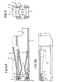
- Figures 5a, 5b and 6 show the contact socket according to the invention, in accordance with the second embodiment, whereby here, in a lateral cross-sectional view, there is shown the sleeve-like enclosure of engagement sleeve 1 by the contact spring 2 which is inserted from the front end.
- two spring legs 12 are formed on contact spring 2 essentially facing each other.
- a mating section 5 which has an essentially U-shaped configuration and encompasses the front end of the engagement sleeve in sections.
- Figure 6 shows that on each side of the engagement sleeve 1 a tab 7 is positioned that also has a U-shaped configuration and which grips the sleeve sections 6 of contact spring 2, which lie in this region.
- the contact spring 2 is hereby secured to engagement sleeve 1.
- the contact spring 2 can be soldered to engagement sleeve 1 or fixedly secured thereto by means of a latching mechanism (not shown).
- Figures 7 and 8 show the layout of the engagement sleeve 1 and the contact spring 2. These representations are also not to scale.
- the layout of the contact spring 2 comprises a latching tongue 8 which, during bending of the contact spring 2, while protruding outwardly is bent upwards in order to allow an anchorage of the contact socket in a receiving chamber (not shown) of a plug.
- a projection 10 is foreseen on the engagement sleeve 1 which is bent away from the engagement sleeve 1 approximately at a right angle, as is shown in Figure 6, in order to form a polarisation of the contact socket
- the contours of the layouts of the engagement sleeves 1 and contact springs 2 are preferably stamped out of flat metal, as shown in Figures 7 and 8. After the stamping operation, the individual engagement sleeves 1 and contact springs 2 are separated and bent. The contact spring 2 and the engagement sleeve 1 are first bent into shape whereafter the contact spring 2 is engaged onto engagement sleeve 1; finally, tabs 7 of engagement sleeve 1 are bent over until the state shown in Figures 5b and 6 is created. However, instead of tabs 7, an additional soldering operation can be foreseen on this section, if desired.
- the engagement sleeve 1 and the contact spring 2 are preferably laser soldered such that a solder pad 9 (from the top direction of the tool) is formed on several locations.
- spring steel material such as X12CrNi
- beryllium copper or steel provided with a precious metal plating is used.
- the contact socket according to the invention is formed in two parts, an engagement sleeve 1 and a contact spring 2 which is engaged in a sleeve-like manner onto the frontal side of engagement sleeve 1.
- the two-part construction allows the material for the engagement sleeve 1 and the contact spring 2 to be separately provided and worked.
- the manufacturing process itself can be optimized and adapted to the individual component.
- the contact spring 2 is additionally provided with one or two spring legs 12 whereby, in the case of one spring leg 12, a counter spring 3 is formed on the engagement sleeve 1.
Landscapes
- Manufacturing Of Electrical Connectors (AREA)
Priority Applications (1)
| Application Number | Priority Date | Filing Date | Title |
|---|---|---|---|
| EP01300886A EP1122832A3 (de) | 2000-01-31 | 2001-01-31 | Kontaktbuchse |
Applications Claiming Priority (3)
| Application Number | Priority Date | Filing Date | Title |
|---|---|---|---|
| EP00101875 | 2000-01-31 | ||
| EP00101875 | 2000-01-31 | ||
| EP01300886A EP1122832A3 (de) | 2000-01-31 | 2001-01-31 | Kontaktbuchse |
Publications (2)
| Publication Number | Publication Date |
|---|---|
| EP1122832A2 true EP1122832A2 (de) | 2001-08-08 |
| EP1122832A3 EP1122832A3 (de) | 2001-09-26 |
Family
ID=26070479
Family Applications (1)
| Application Number | Title | Priority Date | Filing Date |
|---|---|---|---|
| EP01300886A Withdrawn EP1122832A3 (de) | 2000-01-31 | 2001-01-31 | Kontaktbuchse |
Country Status (1)
| Country | Link |
|---|---|
| EP (1) | EP1122832A3 (de) |
Cited By (3)
| Publication number | Priority date | Publication date | Assignee | Title |
|---|---|---|---|---|
| DE102004018492B3 (de) * | 2004-04-14 | 2006-02-09 | Yazaki Europe Ltd., Hemel Hempstead | Steckbuchse zum elektrisch leitenden Verbinden mit einem Steckstift, insbesondere Flachsteckstift |
| DE102006006316B3 (de) * | 2006-02-11 | 2007-10-31 | Tyco Electronics Amp Gmbh | Elektrischer Buchsenkontakt |
| CN102668265A (zh) * | 2009-11-11 | 2012-09-12 | 安普泰科电子韩国有限公司 | 连接器端子 |
Family Cites Families (5)
| Publication number | Priority date | Publication date | Assignee | Title |
|---|---|---|---|---|
| DE9017536U1 (de) * | 1990-12-28 | 1991-03-21 | Amp Inc., Harrisburg, Pa. | Steckverbindungsbuchse |
| US5147230A (en) * | 1991-12-19 | 1992-09-15 | General Motors Corporation | Two piece electrical female terminal |
| GB9405303D0 (en) * | 1994-03-17 | 1994-04-27 | Amp Gmbh | Electrical contact |
| FR2719163A1 (fr) * | 1994-04-22 | 1995-10-27 | Amp France | Borne anti-corrosion par usure, destinée à recevoir une borne complémentaire. |
| EP1057227B1 (de) * | 1998-02-16 | 2003-05-07 | Fci | Elektrischer kontaktanschluss mit einem käfig |
-
2001
- 2001-01-31 EP EP01300886A patent/EP1122832A3/de not_active Withdrawn
Cited By (7)
| Publication number | Priority date | Publication date | Assignee | Title |
|---|---|---|---|---|
| DE102004018492B3 (de) * | 2004-04-14 | 2006-02-09 | Yazaki Europe Ltd., Hemel Hempstead | Steckbuchse zum elektrisch leitenden Verbinden mit einem Steckstift, insbesondere Flachsteckstift |
| US7118428B2 (en) | 2004-04-14 | 2006-10-10 | Yazaki Europe Ltd. | Female terminal for the electrically conductive connection to a terminal pin, especially a flat-pin terminal |
| DE102006006316B3 (de) * | 2006-02-11 | 2007-10-31 | Tyco Electronics Amp Gmbh | Elektrischer Buchsenkontakt |
| CN102668265A (zh) * | 2009-11-11 | 2012-09-12 | 安普泰科电子韩国有限公司 | 连接器端子 |
| EP2499708A4 (de) * | 2009-11-11 | 2013-04-17 | Tyco Electronics Amp Korea Ltd | Steckerklemme |
| US8827754B2 (en) | 2009-11-11 | 2014-09-09 | Tyco Electronics Amp Korea, Ltd. | Connector terminal |
| CN102668265B (zh) * | 2009-11-11 | 2014-11-26 | 安普泰科电子韩国有限公司 | 连接器端子 |
Also Published As
| Publication number | Publication date |
|---|---|
| EP1122832A3 (de) | 2001-09-26 |
Similar Documents
| Publication | Publication Date | Title |
|---|---|---|
| US6231396B1 (en) | Jack connector | |
| JP6342608B2 (ja) | 雌端子 | |
| EP0656673B1 (de) | Anschlussbuchse mit geringer Einsteckkraft | |
| US7080997B2 (en) | Coaxial connector having a switch | |
| EP1528638A2 (de) | Kartenverbinder | |
| WO2006127829A3 (en) | Canted coil spring power terminal and sequence connection system | |
| CA2343248A1 (en) | Socket contact for electrical connectors | |
| US6979235B2 (en) | Electrical plug-in connector with a housing and a high-current contact | |
| CN106663898B (zh) | 连接器系统 | |
| JP3732709B2 (ja) | 電気コネクタ | |
| EP0687033A2 (de) | Buchsenklemme für Hochstrom | |
| US20010019924A1 (en) | Contact socket | |
| US6305993B1 (en) | Contact socket | |
| US20010019921A1 (en) | Contact socket | |
| PL1724878T3 (pl) | Beztulejkowy, tłoczony i formowany styk gniazdowy | |
| US20010019925A1 (en) | Contact socket | |
| US6193561B1 (en) | Electrical plug connector | |
| EP1122830A1 (de) | Kontaktbuchse | |
| EP1148588A2 (de) | Kontaktbuchse | |
| JP2003007408A (ja) | 電気コネクタ | |
| EP1122827A2 (de) | Steckbuchse | |
| CA2186116A1 (en) | Printed circuit board relay with insert connections | |
| JP2005056748A (ja) | 表面実装型コネクタ | |
| EP1122831A2 (de) | Kontaktbuchse | |
| AU783927B2 (en) | Connector with a switching function |
Legal Events
| Date | Code | Title | Description |
|---|---|---|---|
| PUAI | Public reference made under article 153(3) epc to a published international application that has entered the european phase |
Free format text: ORIGINAL CODE: 0009012 |
|
| AK | Designated contracting states |
Kind code of ref document: A2 Designated state(s): AT BE CH CY DE DK ES FI FR GB GR IE IT LI LU MC NL PT SE TR |
|
| AX | Request for extension of the european patent |
Free format text: AL;LT;LV;MK;RO;SI |
|
| PUAL | Search report despatched |
Free format text: ORIGINAL CODE: 0009013 |
|
| AK | Designated contracting states |
Kind code of ref document: A3 Designated state(s): AT BE CH CY DE DK ES FI FR GB GR IE IT LI LU MC NL PT SE TR |
|
| AX | Request for extension of the european patent |
Free format text: AL;LT;LV;MK;RO;SI |
|
| AKX | Designation fees paid | ||
| REG | Reference to a national code |
Ref country code: DE Ref legal event code: 8566 |
|
| STAA | Information on the status of an ep patent application or granted ep patent |
Free format text: STATUS: THE APPLICATION IS DEEMED TO BE WITHDRAWN |
|
| 18D | Application deemed to be withdrawn |
Effective date: 20020327 |