EP1122870A1 - Circuit de puissance avec circuit de variation d'une inductance de lissage - Google Patents
Circuit de puissance avec circuit de variation d'une inductance de lissage Download PDFInfo
- Publication number
- EP1122870A1 EP1122870A1 EP00128256A EP00128256A EP1122870A1 EP 1122870 A1 EP1122870 A1 EP 1122870A1 EP 00128256 A EP00128256 A EP 00128256A EP 00128256 A EP00128256 A EP 00128256A EP 1122870 A1 EP1122870 A1 EP 1122870A1
- Authority
- EP
- European Patent Office
- Prior art keywords
- voltage
- circuit
- choke coil
- output voltage
- smoothing
- Prior art date
- Legal status (The legal status is an assumption and is not a legal conclusion. Google has not performed a legal analysis and makes no representation as to the accuracy of the status listed.)
- Withdrawn
Links
- 238000009499 grossing Methods 0.000 title claims abstract description 99
- 238000004804 winding Methods 0.000 claims abstract description 45
- 230000006698 induction Effects 0.000 claims abstract description 9
- 239000003990 capacitor Substances 0.000 description 18
- 238000010586 diagram Methods 0.000 description 6
- 230000005540 biological transmission Effects 0.000 description 3
- 238000010438 heat treatment Methods 0.000 description 2
- 238000006243 chemical reaction Methods 0.000 description 1
Images




Classifications
-
- H—ELECTRICITY
- H02—GENERATION; CONVERSION OR DISTRIBUTION OF ELECTRIC POWER
- H02M—APPARATUS FOR CONVERSION BETWEEN AC AND AC, BETWEEN AC AND DC, OR BETWEEN DC AND DC, AND FOR USE WITH MAINS OR SIMILAR POWER SUPPLY SYSTEMS; CONVERSION OF DC OR AC INPUT POWER INTO SURGE OUTPUT POWER; CONTROL OR REGULATION THEREOF
- H02M1/00—Details of apparatus for conversion
- H02M1/42—Circuits or arrangements for compensating for or adjusting power factor in converters or inverters
- H02M1/4208—Arrangements for improving power factor of AC input
- H02M1/4266—Arrangements for improving power factor of AC input using passive elements
-
- H—ELECTRICITY
- H02—GENERATION; CONVERSION OR DISTRIBUTION OF ELECTRIC POWER
- H02M—APPARATUS FOR CONVERSION BETWEEN AC AND AC, BETWEEN AC AND DC, OR BETWEEN DC AND DC, AND FOR USE WITH MAINS OR SIMILAR POWER SUPPLY SYSTEMS; CONVERSION OF DC OR AC INPUT POWER INTO SURGE OUTPUT POWER; CONTROL OR REGULATION THEREOF
- H02M1/00—Details of apparatus for conversion
- H02M1/10—Arrangements incorporating converting means for enabling loads to be operated at will from different kinds of power supplies, e.g. from AC or DC
-
- H—ELECTRICITY
- H02—GENERATION; CONVERSION OR DISTRIBUTION OF ELECTRIC POWER
- H02M—APPARATUS FOR CONVERSION BETWEEN AC AND AC, BETWEEN AC AND DC, OR BETWEEN DC AND DC, AND FOR USE WITH MAINS OR SIMILAR POWER SUPPLY SYSTEMS; CONVERSION OF DC OR AC INPUT POWER INTO SURGE OUTPUT POWER; CONTROL OR REGULATION THEREOF
- H02M1/00—Details of apparatus for conversion
- H02M1/12—Arrangements for reducing harmonics from AC input or output
-
- Y—GENERAL TAGGING OF NEW TECHNOLOGICAL DEVELOPMENTS; GENERAL TAGGING OF CROSS-SECTIONAL TECHNOLOGIES SPANNING OVER SEVERAL SECTIONS OF THE IPC; TECHNICAL SUBJECTS COVERED BY FORMER USPC CROSS-REFERENCE ART COLLECTIONS [XRACs] AND DIGESTS
- Y02—TECHNOLOGIES OR APPLICATIONS FOR MITIGATION OR ADAPTATION AGAINST CLIMATE CHANGE
- Y02B—CLIMATE CHANGE MITIGATION TECHNOLOGIES RELATED TO BUILDINGS, e.g. HOUSING, HOUSE APPLIANCES OR RELATED END-USER APPLICATIONS
- Y02B70/00—Technologies for an efficient end-user side electric power management and consumption
- Y02B70/10—Technologies improving the efficiency by using switched-mode power supplies [SMPS], i.e. efficient power electronics conversion e.g. power factor correction or reduction of losses in power supplies or efficient standby modes
Definitions
- the present invention relates to a power circuit for an electrical apparatus for rectifying and smoothing commercial power of AC 100 V to 240 V to obtain a direct-current voltage.
- Electrical appliances such as televisions, personal computers and air conditioners for use at home are designed to operate on commercial power distributed to each home.
- Conventional power circuits typically used in the electrical appliances operating on commercial power include a circuit of a capacitor input type comprising a smoothing capacitor.
- Fig. 1 is a circuit diagram showing an example of a conventional power circuit of such a capacitor input type.
- the conventional power circuit shown in Fig. 1 comprises diode bridge 11 for performing full-wave rectification of an alternating voltage output from commercial power 10, smoothing circuit 3 for smoothing a pulsating flow voltage output from diode bridge 11, and DC-DC converter 5 for obtaining a desired voltage from a direct-current voltage output from smoothing circuit 3.
- Smoothing circuit 3 comprises smoothing choke coil 20 for smoothing a current flow and smoothing capacitor 21 which is charged to smooth a voltage.
- One terminal of smoothing choke coil 20 is connected to an output of diode bridge 11, and smoothing capacitor 21 is connected between the other terminal thereof and a ground potential.
- DC-DC converter 5 comprises switching transformer 30 for performing voltage conversion, rectifier diode 40 for rectifying output from switching transformer 30, smoothing capacitor 41 for smoothing output from switching transformer 30, error voltage detecting circuit 50 for detecting an error between an output voltage from DC-DC converter 5 and a desired voltage, error voltage transmission circuit 51 for transmitting the error in the output voltage, switching control circuit 32 for control to compensate for the error in the output voltage, and switching element 31 which is turned on/off by switching control circuit 32 for controlling a current flowing through a primary winding of switching transformer 30 to compensate for the error in the output voltage.
- One terminal of the primary winding of switching transformer 30 is connected to the other terminal of smoothing choke coil 20, the other terminal of the primary winding of switching transformer 30 is connected to switching element 31, and one terminal of a secondary winding of switching transformer 30 is connected to an output through rectifier diode 40.
- the other terminal of the secondary winding of switching transformer 30 is grounded, and smoothing capacitor 41 is connected between the output and a ground potential.
- the power supply voltage of commercial power 10 is rectified in diode bridge 11, smoothed in smoothing choke coil 20 and smoothing capacitor 21, and supplied to the one terminal of the primary winding of switching transformer 30.
- Output from the secondary winding of switching transformer 30 is rectified in rectifier diode 40, smoothed in smoothing capacitor 41, and output as a signal with a desired voltage.
- Switching control circuit 32 controls the operation of switching element 31 based on the output signal which is fed back through error voltage detecting circuit 50 and error voltage transmission circuit 51 to compensate for the error in the direct-current voltage.
- Voltages of commercial power in specifications vary from country to country, and specifically, various alternating voltages ranging from AC 100 V to AC 240 V are standardized in respective countries.
- the standards are broadly divided into a 100 V system which employs a voltage value near 100V and a 200 V system which employs a voltage value near 200 V. It is desirable that electrical apparatuses for home use are used in common at home and overseas.
- the power circuit according to the present invention includes a smoothing choke coil inductance varying circuit within a smoothing circuit.
- the smoothing choke coil inductance varying circuit flows a current through a secondary winding of the smoothing choke coil to provide induction based on a pulsating flow voltage obtained by rectifying an alternating voltage in a diode bridge, thereby performing such a control that an inductance value of a primary winding of the smoothing choke coil is at the maximum when the pulsating flow voltage is zero volt, is reduced with an increase in the pulsating flow voltage, reaches a predetermined value when the pulsating flow voltage is at the maximum, and is increased with a reduction in the pulsating flow voltage.
- Such control of the inductance value of the smoothing choke coil enables an increase in the inductance value to enhance the improvement in the power factor when current is small and the power factor is low, and a reduction in the inductance to restrict the amount of produced heat when the current is large.
- the smoothing choke coil inductance varying circuit comprises means for determining whether the alternating voltage is of 100 V system or 200 V system based on the output voltage from the diode bridge to notify the smoothing choke coil of the determination result, and the smoothing choke coil includes means for changing its inductance value in accordance with the notification.
- a conduction angle can be increased in a range from 100 V to 240 V to improve the power factor.
- a power circuit according to a first embodiment of the present invention comprising diode bridge 12 for performing full-wave rectification of an alternating voltage output from commercial power 10, smoothing circuit 1 for smoothing a pulsating flow voltage output from diode bridge 12, and DC-DC converter 5 for obtaining a desired direct-current voltage from a direct-current voltage output from smoothing circuit 1.
- Smoothing circuit 1 comprises smoothing choke coil 22 having a primary winding and a secondary winding for smoothing a current flow by the primary winding, smoothing capacitor 21 which is charged to smooth a voltage, diode bridge 24 for performing full-wave rectification of an alternating voltage output from commercial power 10, and smoothing choke coil inductance varying circuit 23 for providing induction through the secondary winding of smoothing choke coil 22 based on output from diode bridge 24 to variably control the inductance value of the primary winding.
- smoothing capacitor 21 is connected between the other terminal thereof and a ground potential.
- An output from diode bridge 24 is supplied to smoothing choke coil inductance varying circuit 23, and an output from smoothing choke coil inductance varying circuit 23 is connected to both ends of the secondary winding of smoothing choke coil 22.
- DC-DC converter 5 has a configuration similar to that of DC-DC converter 5 in the conventional power circuit shown in Fig. 1, the description thereof is omitted.
- smoothing choke coil inductance varying circuit 23 comprises voltage dividing circuit 230 for dividing output from diode bridge 24, and output circuit 231 for flowing a current through the secondary winding of smoothing choke coil 22 to provide induction based on output from voltage dividing circuit 230, thereby controlling the inductance value of the primary winding.
- the power supply voltage of commercial power 10 is rectified in diode bridge 12, smoothed in smoothing choke coil 22 and smoothing capacitor 21, and supplied to the side of a primary winding of switching transformer 30.
- Output from a secondary winding of switching transformer 30 is rectified in rectifier diode 40, smoothed in smoothing capacitor 41, and output as a signal with a desired voltage.
- Switching control circuit 32 controls switching element 31 based on a signal which is fed back through error voltage detecting circuit 50 and error voltage transmission circuit 51. Thus, the error in the direct-current voltage is compensated for.
- the power supply voltage of commercial power supply 10 is also rectified in diode bridge 24, and the resultant pulsating flow voltage is divided by voltage dividing circuit 230 and supplied to output circuit 231.
- Output circuit 231 controls a current flowing though the secondary winding of smoothing choke coil 22 based on the pulsating flow voltage to variably control the inductance value of the primary winding of smoothing choke coil 22.
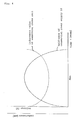
- Fig. 4 shows a graph illustrating changes in the inductance value of the primary winding of the smoothing choke coil.
- the inductance value of the primary winding of smoothing choke coil 22 is set to be at a predetermined value when the pulsating flow voltage is at the maximum, and is controlled to become larger as the voltage deviates from the peak in a region except the maximum voltage.
- Induction is provided through the secondary winding based on changes in voltage of commercial power 10 to control the inductance value of the primary winding of smoothing choke coil 22 such that the value becomes larger as the pulsating flow voltage deviates from the peak.
- the inductance value can be increased to enhance the improvement in the power factor when current is small and the power factor is low, and the inductance can be reduced to restrict the amount of produced heat when the current is large, thereby enabling the improvement in the power factor as well as the restriction of the amount of produced heat.
- FIG. 5 there is shown a power circuit according to a second embodiment of the present invention which differs from that of the first embodiment only in a smoothing circuit. Since the remaining portions are configured similarly to the first embodiment, the description thereof is omitted.
- Smoothing circuit 2 comprises smoothing choke coil 25 which includes a primary winding and a secondary winding, smooths a current flow by the primary winding, and allows the use of an inductance value suitable for commercial power supply of 100 V system or 200 V system in response to instructions from the outside, smoothing capacitor 21 which is charged to smooth a voltage, diode bridge 24 for performing full-wave rectification of an alternating voltage output from commercial power 10, and smoothing choke coil inductance varying circuit 26 for providing induction through the secondary winding of smoothing choke coil 25 based on output from diode bridge 24 to variably control the inductance value of the primary winding and for determining whether the commercial power supply is of 100 V system or 200 V system to notify smoothing choke coil 25 of the determination result.
- smoothing choke coil 25 which includes a primary winding and a secondary winding, smooths a current flow by the primary winding, and allows the use of an inductance value suitable for commercial power supply of 100 V system or 200 V system in response to instructions from the outside
- smoothing capacitor 21 which
- smoothing choke coil 25 One terminal of the primary winding of smoothing choke coil 25 is connected to an output from diode bridge 12, and smoothing capacitor 21 is connected between the other terminal thereof and a ground potential.
- An output from diode bridge 24 is supplied to smoothing choke coil inductance varying circuit 26, and outputs from smoothing choke coil inductance varying circuit 26 are connected to both ends of the secondary winding of smoothing choke coil 22.
- a signal indicating the determination result of whether the commercial power supply is of 100 V system or 200 V system is connected to smoothing choke coil 25.
- DC-DC converter 5 has a configuration similar to that of the DC-DC converter of the conventional power circuit shown in Fig. 1, the description thereof is omitted.
- smoothing choke coil inductance varying circuit 26 comprises, in addition to voltage dividing circuit 230 and output circuit 231 configured similarly to the counterparts in smoothing choke coil inductance varying circuit 23 in the first embodiment, voltage dividing circuit 261 for dividing output from diode bridge 24, rectifier circuit 262 for rectifying output from voltage dividing circuit 261, reference voltage producing circuit 263 for producing a reference voltage used to determine whether commercial power supply 10 is of 100 V system or 200 V system, and comparing circuit 264 for comparing the reference voltage with the voltage of output from rectifier circuit 262 to determine whether commercial power system 10 is of 100 V system or 200 V system.
- the voltages of output signals from voltage dividing circuit 230 and reference voltage producing circuit 263 are set respectively such that the voltage of output from voltage dividing circuit 230 is lower than the reference voltage when the commercial power supply is of 100 V system, or the voltage of output from voltage dividing circuit 230 is higher than the reference voltage when the commercial power supply is of 200 V system.
- Smoothing choke coil inductance varying circuit 26 determines whether commercial power supply 10 is of 100 V system or 200 V system, and the determination result is notified to smoothing choke coil 25.
- Smoothing choke coil 25 refers to an inductance value suitable for the 100 V system when the determination result indicates the 100 V system, or an inductance value suitable for the 200 V system when the determination result indicates the 200 V system. Control for varying the inductance value is performed similarly to the first embodiment with the inductance value suitable for the 100 V system or 200 V system.
- the power circuit of the second embodiment automatically determines whether the commercial power supply is of 100 V system or 200 V system to perform control with an inductance value suitable therefor, a conduction angle can be increased in a range from 100 V to 240 V to improve the power factor, thereby making it possible to render the circuit usable in common at home and overseas.
Landscapes
- Engineering & Computer Science (AREA)
- Power Engineering (AREA)
- Rectifiers (AREA)
Applications Claiming Priority (2)
| Application Number | Priority Date | Filing Date | Title |
|---|---|---|---|
| JP37149599A JP3341832B2 (ja) | 1999-12-27 | 1999-12-27 | 電源回路および平滑方法 |
| JP37149599 | 1999-12-27 |
Publications (1)
| Publication Number | Publication Date |
|---|---|
| EP1122870A1 true EP1122870A1 (fr) | 2001-08-08 |
Family
ID=18498808
Family Applications (1)
| Application Number | Title | Priority Date | Filing Date |
|---|---|---|---|
| EP00128256A Withdrawn EP1122870A1 (fr) | 1999-12-27 | 2000-12-22 | Circuit de puissance avec circuit de variation d'une inductance de lissage |
Country Status (6)
| Country | Link |
|---|---|
| US (1) | US6341074B2 (fr) |
| EP (1) | EP1122870A1 (fr) |
| JP (1) | JP3341832B2 (fr) |
| KR (1) | KR100386865B1 (fr) |
| CA (1) | CA2329573C (fr) |
| TW (1) | TW494611B (fr) |
Families Citing this family (5)
| Publication number | Priority date | Publication date | Assignee | Title |
|---|---|---|---|---|
| EP1601089B1 (fr) * | 2004-05-25 | 2010-08-11 | Panasonic Corporation | Dispositif d'alimentation de puissance et climatisation l'utilisant |
| US7355867B2 (en) * | 2004-08-17 | 2008-04-08 | Elster Electricity, Llc | Power supply for an electric meter having a high-voltage regulator that limits the voltage applied to certain components below the normal operating input voltage |
| US7738266B2 (en) * | 2006-05-26 | 2010-06-15 | Cambridge Semiconductor Limited | Forward power converter controllers |
| FR2923328B1 (fr) * | 2007-11-06 | 2010-01-29 | Peugeot Citroen Automobiles Sa | Dispositif d'interface entre deux parties d'un reseau electrique, a prelevement d'energie pour la compensation de chutes de tension |
| TWI504123B (zh) * | 2013-11-01 | 2015-10-11 | Hep Tech Co Ltd | Flow Transformer Transformer and Its Transforming Method |
Citations (3)
| Publication number | Priority date | Publication date | Assignee | Title |
|---|---|---|---|---|
| JPS5295026A (en) * | 1976-02-04 | 1977-08-10 | Hitachi Ltd | Dc/dc converter |
| DE4029447A1 (de) * | 1990-09-17 | 1992-03-19 | Schmidding Wilh Gmbh & Co | Ozonerzeugungsanlage mit ozonerzeugungselementen und mit einem wechselrichter |
| EP0945969A1 (fr) * | 1996-12-10 | 1999-09-29 | Matsushita Refrigeration Company | Unite de puissance |
Family Cites Families (6)
| Publication number | Priority date | Publication date | Assignee | Title |
|---|---|---|---|---|
| DE3268691D1 (en) * | 1982-09-30 | 1986-03-06 | Ant Nachrichtentech | Direct voltage converter with a pulse width controlled semiconductor switch |
| JPH07264859A (ja) | 1994-03-18 | 1995-10-13 | Sony Corp | 力率改善整流回路 |
| JPH0837778A (ja) | 1994-07-26 | 1996-02-06 | Sony Corp | スイッチング電源回路 |
| JP3404936B2 (ja) | 1994-09-08 | 2003-05-12 | ソニー株式会社 | 電流共振型スイッチング電源回路 |
| JP2799410B2 (ja) | 1995-02-02 | 1998-09-17 | サンケン電気株式会社 | 直流コンバータ装置 |
| JP2917857B2 (ja) | 1995-05-17 | 1999-07-12 | サンケン電気株式会社 | 共振型コンバータ装置 |
-
1999
- 1999-12-27 JP JP37149599A patent/JP3341832B2/ja not_active Expired - Fee Related
-
2000
- 2000-12-21 TW TW089127534A patent/TW494611B/zh not_active IP Right Cessation
- 2000-12-21 US US09/740,976 patent/US6341074B2/en not_active Expired - Fee Related
- 2000-12-22 EP EP00128256A patent/EP1122870A1/fr not_active Withdrawn
- 2000-12-22 CA CA002329573A patent/CA2329573C/fr not_active Expired - Fee Related
- 2000-12-26 KR KR10-2000-0081731A patent/KR100386865B1/ko not_active Expired - Fee Related
Patent Citations (3)
| Publication number | Priority date | Publication date | Assignee | Title |
|---|---|---|---|---|
| JPS5295026A (en) * | 1976-02-04 | 1977-08-10 | Hitachi Ltd | Dc/dc converter |
| DE4029447A1 (de) * | 1990-09-17 | 1992-03-19 | Schmidding Wilh Gmbh & Co | Ozonerzeugungsanlage mit ozonerzeugungselementen und mit einem wechselrichter |
| EP0945969A1 (fr) * | 1996-12-10 | 1999-09-29 | Matsushita Refrigeration Company | Unite de puissance |
Non-Patent Citations (1)
| Title |
|---|
| PATENT ABSTRACTS OF JAPAN vol. 001, no. 153 (E - 072) 8 December 1977 (1977-12-08) * |
Also Published As
| Publication number | Publication date |
|---|---|
| US20010005323A1 (en) | 2001-06-28 |
| US6341074B2 (en) | 2002-01-22 |
| KR100386865B1 (ko) | 2003-06-12 |
| CA2329573A1 (fr) | 2001-06-27 |
| CA2329573C (fr) | 2003-12-09 |
| TW494611B (en) | 2002-07-11 |
| JP3341832B2 (ja) | 2002-11-05 |
| KR20010062692A (ko) | 2001-07-07 |
| JP2001186769A (ja) | 2001-07-06 |
Similar Documents
| Publication | Publication Date | Title |
|---|---|---|
| US7170761B2 (en) | Switching power supply circuit | |
| US6396717B2 (en) | Switching power supply having an improved power factor by voltage feedback | |
| CN102948062B (zh) | 多相转换器 | |
| JPH07143751A (ja) | 電源回路 | |
| US7388760B2 (en) | Switching power supply circuit | |
| US6388902B1 (en) | Switching power supply circuit | |
| JP2002252983A (ja) | 交流直流変換回路 | |
| KR20220099079A (ko) | 커패시터 전압에 따라 보조 권선 전압을 감지하는 플라이백 컨버터 | |
| JPH06209574A (ja) | 電源回路 | |
| JP2001008452A (ja) | 電源装置 | |
| US6341074B2 (en) | Power circuit with smoothing choke coil inductance varying circuit | |
| CN112655147B (zh) | 开关电源装置 | |
| EP0802615B1 (fr) | Alimentation de puissance à découpage | |
| CN216959689U (zh) | 一种电源供应系统 | |
| WO2020116033A1 (fr) | Dispositif de fourniture d'énergie sans contact | |
| JPH0646535A (ja) | 充電器 | |
| CN115706531A (zh) | 功率转换器控制器、功率转换器及操作功率转换器的方法 | |
| US20220345032A1 (en) | High Efficiency Power Factor Corrected Power Converters | |
| JP4715985B2 (ja) | スイッチング電源装置 | |
| JPH11308858A (ja) | スイッチングレギュレータ電源回路 | |
| JP2004072866A (ja) | 電源装置 | |
| JP2000209855A (ja) | 電源装置 | |
| CN108092420B (zh) | 一种电能接收端的控制方法及无线电能传输装置 | |
| JPH0242075Y2 (fr) | ||
| JP2004328948A (ja) | スイッチング電源回路およびこれを備えたスイッチングレギュレータ |
Legal Events
| Date | Code | Title | Description |
|---|---|---|---|
| PUAI | Public reference made under article 153(3) epc to a published international application that has entered the european phase |
Free format text: ORIGINAL CODE: 0009012 |
|
| AK | Designated contracting states |
Kind code of ref document: A1 Designated state(s): DE FR GB |
|
| AX | Request for extension of the european patent |
Free format text: AL;LT;LV;MK;RO;SI |
|
| 17P | Request for examination filed |
Effective date: 20010628 |
|
| AKX | Designation fees paid |
Free format text: DE FR GB |
|
| RAP1 | Party data changed (applicant data changed or rights of an application transferred) |
Owner name: NEC PLASMA DISPLAY CORPORATION |
|
| RAP1 | Party data changed (applicant data changed or rights of an application transferred) |
Owner name: PIONEER PLASMA DISPLAY CORPORATION |
|
| RAP1 | Party data changed (applicant data changed or rights of an application transferred) |
Owner name: PIONEER CORPORATION |
|
| STAA | Information on the status of an ep patent application or granted ep patent |
Free format text: STATUS: THE APPLICATION IS DEEMED TO BE WITHDRAWN |
|
| 18D | Application deemed to be withdrawn |
Effective date: 20070703 |