EP1122893A1 - Übertragungsgerät und verfahren zur signalpunkterzeugung - Google Patents
Übertragungsgerät und verfahren zur signalpunkterzeugung Download PDFInfo
- Publication number
- EP1122893A1 EP1122893A1 EP99923857A EP99923857A EP1122893A1 EP 1122893 A1 EP1122893 A1 EP 1122893A1 EP 99923857 A EP99923857 A EP 99923857A EP 99923857 A EP99923857 A EP 99923857A EP 1122893 A1 EP1122893 A1 EP 1122893A1
- Authority
- EP
- European Patent Office
- Prior art keywords
- signal
- transmission
- transmission apparatus
- filter
- point
- Prior art date
- Legal status (The legal status is an assumption and is not a legal conclusion. Google has not performed a legal analysis and makes no representation as to the accuracy of the status listed.)
- Withdrawn
Links
Images








Classifications
-
- H—ELECTRICITY
- H04—ELECTRIC COMMUNICATION TECHNIQUE
- H04L—TRANSMISSION OF DIGITAL INFORMATION, e.g. TELEGRAPHIC COMMUNICATION
- H04L27/00—Modulated-carrier systems
- H04L27/32—Carrier systems characterised by combinations of two or more of the types covered by groups H04L27/02, H04L27/10, H04L27/18 or H04L27/26
- H04L27/34—Amplitude- and phase-modulated carrier systems, e.g. quadrature-amplitude modulated carrier systems
- H04L27/36—Modulator circuits; Transmitter circuits
- H04L27/366—Arrangements for compensating undesirable properties of the transmission path between the modulator and the demodulator
- H04L27/367—Arrangements for compensating undesirable properties of the transmission path between the modulator and the demodulator using predistortion
-
- H—ELECTRICITY
- H04—ELECTRIC COMMUNICATION TECHNIQUE
- H04B—TRANSMISSION
- H04B1/00—Details of transmission systems, not covered by a single one of groups H04B3/00 - H04B13/00; Details of transmission systems not characterised by the medium used for transmission
- H04B1/38—Transceivers, i.e. devices in which transmitter and receiver form a structural unit and in which at least one part is used for functions of transmitting and receiving
-
- H—ELECTRICITY
- H04—ELECTRIC COMMUNICATION TECHNIQUE
- H04B—TRANSMISSION
- H04B1/00—Details of transmission systems, not covered by a single one of groups H04B3/00 - H04B13/00; Details of transmission systems not characterised by the medium used for transmission
Definitions
- the present invention relates to a transmission apparatus and a method of signal-point generation suitable for use in such a transmission apparatus, more particularly relates to a transmission apparatus and a method of signal-point generation suitable for high speed transmission of data through a narrow band radio transmission path.
- monitoring of the level of rivers or the intakes of dams is essential.
- remote monitoring employing an optical fiber as a transmission line is used. If an optical fiber is used as transmission line, however, there is a possibility of disconnection of the transmission line due to some reason or another. If this happens, remote monitoring becomes disabled and there can be remarkable harm to the public.
- such a radio transmission apparatus is comprised of a pair of a radio transmitter and a modem transmitter at the transmitting side and a pair of a radio receiver and modem receiver at the receiving side.
- radio device parts due to various regulations, however, so those parts cannot be freely reconfigured. This is the above other difficult problem. Therefore, whether an over 9600 bps radio transmission apparatus can be realized or not depends on the performance of the modem parts.
- the present invention has as its object, in view of the above problems, the provision of a transmission apparatus (mainly modem) able to secure a sufficient operating margin and a method of signal-point generation using this transmission apparatus to increase the operating margin.
- a transmission apparatus mainly modem
- Figure 19 is a view of a general remote monitoring system of an example to which the present invention can be applied. In particular, it shows a dam monitoring system.
- This dam monitoring system is comprised of a remote terminal having a camera for monitoring a remote dam, a monitoring center for receiving the video data or audio data obtained by the remote terminal, and a transmission path connecting the remote terminal and the monitoring center.
- the transmission path sends a moving image or other monitoring information from the remote terminal to the monitoring center, but normally an optical fiber is used as the transmission path.
- Transmission apparatuses are provided at the two ends of the optical fiber for transmission of the monitoring information.
- the present invention relates to a modem comprising part of such a radio transmission apparatus.
- the following explanation will be given taking as an example a modem comprising part of such a radio transmission apparatus.
- the idea of the present invention can be applied to other transmission apparatuses as well, for example, transmission apparatuses provided with CATV modems or can be applied to various modems such as modems built into DVD apparatuses.
- Figure 20 is a view of a general radio transmission system.
- 1T indicates a radio transmitter ("T” indicates a transmitter), 1R a radio receiver, and 3 a transmission path (radio) connecting the two.
- the radio transmitter 1T comprises a preemphasis filter 11 for reducing the noise in the higher band of the input analog transmission signal (modem signal), a limiter 12 for limiting the radio power in the air to within regulations, and an FM demodulator 13 for transmitting the input analog signal to the transmission path 3 by radio.
- a preemphasis filter 11 for reducing the noise in the higher band of the input analog transmission signal (modem signal)
- a limiter 12 for limiting the radio power in the air to within regulations
- an FM demodulator 13 for transmitting the input analog signal to the transmission path 3 by radio.
- the radio receiver 1R comprises an FM demodulator 31 for demodulating an FM modulated and transmitted signal and a deemphasis filter 32 applying inverse filter characteristics to an analog signal preemphasized at the transmitting side to restore the original analog received signal (modem signal).
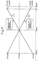
- Figure 21 is a view of the filter characteristics of the preemphasis filter and deemphasis filter.
- the preemphasis filter 11 of the transmitting side acts to pull up the higher band side of the analog signal to be sent (curve ⁇ 11> in the figure).
- the deemphasis filter 32 on receiving side acts to apply characteristics inverse to the characteristics shown by the above curve ⁇ 11> to the received analog signal (curve ⁇ 32> in the figure).
- the preemphasis is given in advance at the transmitting side because general radios are designed to particularly match with voice analog signals. That is, they are configured to compensate for characteristics distinctive to the voice band, that is, the peaking at about 1 kHz and the rapid drop in the level the further higher the band.
- a modem transmitter is connected to the input side of the radio transmitter 1T and a modem receiver is connected to the output side of the radio receiver 1R to enable the transmission of data between the monitoring center and a remote terminal.
- the preemphasis filter 11 and the deemphasis filter 32 are built in. Therefore, the frequency characteristics of the analog signals in the radios (1T, 1R) are not flat as will be clear from Fig. 21. Such not flat frequency characteristics are optimal for transmitting an analog signal of voice etc. by a high quality. They are not suitable however for transmission of video data, audio data, or other data through a modem. The reason is that high quality data transmission requires flat frequency characteristics. In the end, the above-mentioned preemphasis filter characteristics distinctive to the radio transmitter 1T become an obstacle to the desired data transmission.
- the limiter 12 is a component for limiting the radio power in the air to within regulations. Due to the limiting action of the limiter 12, however, faithful transmission of the waveform ends up being inhibited.
- the transmission band of the radios (1T, 1R) is 2700 Hz.
- the distortion of the above transmission output signal changes in degree depending on the frequency. Further, the distortion of the transmission output signal becomes larger the larger the peak factor of the transmission input signal from the modem transmitter.
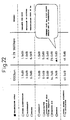
- Figure 22 is a view for explaining the performance sought in a conventional radio transmission system.
- the top section shows the data transmission speed.
- “1200 bps” is the current maximum data transmission speed
- “V.29 9600 bps” is the data transmission speed to be realized using a V.29 modem.
- the leftmost column in the figure shows the parameters defined by government regulations (for example, the regulations set by the Ministry of Construction in Japan).
- the carrier frequency of the modem is moved to match with the carrier frequency of the radio. Due to this, the transmission energy on the radio transmission line 3 is made to move to the center of the transmission band of the radio transmission line.
- the carrier frequency (center frequency) of a general V.29 modem is set to 1700 Hz, this is changed to 1650 Hz in the modem of the present invention.
- 1650 Hz is the carrier frequency normally set for a radio.
- the modem transmitter is provided with a deemphasis filter having filter characteristics inverse with the preemphasis filter 11 distinctive to the radio transmitter. Further, the modem transmitter is provided with an emphasis filter having filter characteristics inverse to the deemphasis filter 32 distinctive to the radio receiver. In this case, it is preferable to have the inverse filter characteristics appear only for the high band of over a predetermined frequency and to give flat characteristics in the low band below that predetermined frequency (see later explained Fig. 16).
- the number of signal points is increased from the past on the signal constellation coordinate system and redundancy is given to the signal points.
- the above redundancy is given to the plurality of signal points at coordinates away from the origin of the coordinate system, that is, at the outside, among a set of signal points in the signal constellation coordinate system. This is because the outside signal points have larger peak values and energy values and have large effects on the reduction of the peak factor. Due to this, the redundancy to be added is kept to a minimum and the peak factor can be minimized.
- the in-phase components are emphasized. By doing this, the energy near the carrier frequency ends up being increased. If a signal is passed through the deemphasis filter 29 with the energy increased as it is, part of the output signal from the filter 29 will be removed and the energy of the output signal will end up falling. Therefore, the signal is shifted to the lower band to prevent a reduction in this energy as much as possible.
- Figure 1 is a view of the basic configuration of a transmission system based on the present invention. Note that similar components are assigned the same reference numerals or symbols throughout the figures.
- 5 is a transmission system according to the present invention.
- the transmission data TD from the remote terminal is given through the transmission system 5 as received data RD to the monitoring center.
- modem transmitter and modem receiver are shown by reference numerals 2T and 2R in Fig. 1.
- These modem transmitter and receiver 2T and 2R and radio transmitter and receiver 1T and 1R are expressed by the six functional blocks I to VI.
- the functional block III forming the radio transmitter 1T of the transmitting side and the functional block IV forming the radio receiver 1R of the receiving side facing it through the transmission path 3 are completely the same as the configurations shown in Fig. 20. No changes are made in the present invention to the radios (1T, 1R).
- the modem transmitter 2T is comprised of the functional blocks I and II.
- the functional block I is a coding unit and codes the input transmission data TD.
- the encoded data is input to the modulation/deemphasis processor shown as the functional block II where it is modulated and deemphasized and becomes the transmission input signal to the radio transmitter 1T.
- the functional block III forming the radio transmitter 1T preemphasizes (11) the transmission input signal, limits the signal level by the limiter (12), then performs FM modulation (13) and sends the result to the receiving side.
- the functional block IV forming the radio receiver 1R of the receiving side demodules the received signal by FM demodulation (31), deemphasizes it (32), then inputs the result to the modem receiver 2R.
- the functional block V forming the modem receiver 2R emphasizes the output signal from the radio receiver 1R, demodules it, then decodes it in the decoding unit forming the functional block VI and outputs the received data RD.
- the radios (1T, 1R) shown in Fig. 1 are radios for transmitting and receiving a voice signal. Therefore, preemphasis and deemphasis are performed.
- Figure 2 is a view of the specific configuration of the modem transmitter shown in Fig. 1.
- the modem transmitter 2T is comprised of a scrambler (SCR) 21 for randomizing (gray coding) the transmission data TD input from for example a remote terminal, a gray/natural converter (G/N) 22 for converting a gray code to a natural code, an adder circuit (AD) 23 for adding the phase of the signal (considering the fact that the absolute phase on the line is unstable and enabling reading of the signal by the relative phase at the receiving side), a signal-point generating circuit (SPG) 24 for selecting and outputting one signal point corresponding to a for example 4-bit output from the adder circuit 23 from the plurality of signal points, a frequency movement circuit (ROT) 25 for frequency rotation explained later, a roll-off filter (ROF) 26 for wave shaping the output signal from the frequency movement circuit 25, a modulator (MOD) 27 for modulating the carrier by the wave shaped output signal, a carrier generator (CRR) 28 for generating a carrier (1650 Hz) and applying it to the modulator 27, and a
- the frequency movement circuit 25 is provided for the following reasons. As explained above, by emphasizing the in-phase components, the energy near the carrier frequency ends up increasing, but if passing the signal through the deemphasis filter 29 with the energy increased as it is, part of the output signal from the filter 29 will end up being removed and the energy of the output signal will end up falling, so to prevent such a reduction in the energy as much as possible, it is preferable to shift the signal to the lower band. Therefore, the frequency movement circuit 25 is introduced.
- Figure 3 is a view of the specific configuration of the modem receiver shown in Fig. 1.
- the modem receiver 2R is comprised of an emphasis filter (EMP) 41 receiving the received input signal Sr input from the radio receiver 1R and applying filter characteristics inverse to the characteristics of the deemphasis filter 22 of the receiver 1R, a demodulator (DEM) 42 for demodulating the output signal from the filter 41 by a predetermined carrier, a carrier generator (CRR) 43 for generating a carrier (1650 Hz) and applying it to the demodulator 42, a roll-off filter (ROF) 44 for wave shaping the demodulated output signal, an automatic gain controller (AGC) 45 for holding the level of the output signal from the filter 44 constant, an automatic equalizer (EQL) 46 applying processing to the output signal from the AGC 45 to suppress inter-symbol interference, an inverse frequency movement circuit (inverse ROT) 47 for frequency movement inverse to the frequency movement at the ROT 25 of the transmitting side with respect to the output signal of the EQL 46, a carrier automatic phase control circuit (CAPC) 49 for controlling the carrier phase of
- a subtractor circuit (SUB) 50 for performing an inverse operation to the adder circuit 23 of the transmitting side on the for example 4-bit output from the DEC 49
- an N/G converter 51 for performing natural/gray conversion inverse to the G/N converter 22 of the transmitting side on the output signal of the SUB 50
- a descrambler (DSCR) 52 for applying the inverse operation to the scrambler 21 of the transmitting side on the output signal after N/G conversion.
- the output of the descrambler 52 becomes the received data RD to be received at for example the monitoring center.
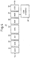
- Figure 4 is a view of the specific configuration of a conventional modem transmitter
- Fig. 5 is a view of the specific configuration of a conventional modem receiver.
- the final block (LEQ) 33 in Fig. 4 is a transmitting side line equalizer
- the first block (LEQ) 53 in Fig. 5 is a receiving side line equalizer.
- the model transmitter 2T according to the present invention is provided with the frequency movement circuit (ROT) 25, while the conventional modem transmitter 2T does not employ a configuration corresponding to the ROT 25.
- the frequency of the carrier signal generated by the carrier generating circuit (CRR) differs between the transmitter according to the present invention (1650 Hz) and the transmitter of a V.29 modem (1700 Hz).
- the signal output side is provided with a deemphasis filter 29, while there is no filter corresponding to this at the conventional modem transmitter.
- the modem receiver 2R according to the present invention differs from the conventional modem receiver 2R in that the input side of the analog signal is provided with an emphasis filter (EMP) 41, the frequency of the carrier signal generated by the carrier generating circuit (CRR) differs from that of the V.29 modem (1650 Hz/1700 Hz), and an inverse frequency movement circuit (inverse ROT) 47 is provided.
- EMP emphasis filter
- CRC carrier generating circuit
- the improvement (iii) is an improvement of the peak factor and an improvement of the S/N error rate.
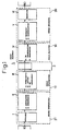
- Figures 6a and 6b are waveform diagrams for explaining the improvement of the peak factor.
- Figure 6a is a waveform diagram of the improvement (iii) according to the present invention and shows the impulse responses of preceding and succeeding signals.
- Fig. 6b shows the impulse responses when the improvement (iii) is not sought.
- the ordinate indicates the amplitude of the signals, while the abscissa indicates the time.
- FIG. 6a A shows the waveform of the signal first output, while B shows the waveform of the signal output later after the signal A. Further, the combined waveform of the signals A and B is shown by C (same for Fig. 6b).
- the preceding signal A and the succeeding signal B are separated by peak position by exactly one lattice shown in the figure, but are in phase. Therefore, the inter-symbol interference becomes small and a stable waveform is obtained. Further, the peak value of the signal tends to decline. That is, if the signal A and the signal B become in phase, the peak factor is improved.
- the peak positions of the signal A and the signal B are the same as in Fig. 6a, but the phases become opposite.
- the inter-symbol interference becomes large and further the combined waveform C oscillates as illustrated. Further, the peak value of the combined waveform C tends to increase.
- processing is performed at the signal point generating circuit 24 of Fig. 2 so that the signal points of the preceding and succeeding signals become in phase. Due to this, the inter-symbol interference is made smaller and the peak factor is reduced.
- the number of signal points on the signal constellation coordinate system is increased from the 16 of the past to 24 so as to increase the in-phase components. That is, redundancy is given to the signal points of the transmission data TD.
- the peak factor is reduced by aligning the phases of the signal points. Along with this, the S/N error rate is also improved. This will be explained in more specifically below.
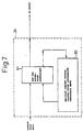
- Figure 7 is a view of the specific configuration of the signal point generating circuit in Fig. 2.
- the signal point generating circuit (SPG) 24 of Fig. 2 is one considerably different from the conventional signal point generating circuit (SPG) 24' shown in Fig. 4. This new signal point generating circuit 24 contributes to the above improvement (iii).
- the signal point generating circuit 24 is mainly comprised of the signal point generation ROM 61 and register 62.
- the signal point generating circuit 24 of the transmission data TD stores the signal-point output information of the transmission data TD in the register 62 and feeds it back to the address input of the ROM 61. Inside the ROM 61, the signal point to be actually transmitted is selected from the currently input data and the information of the signal point of the data transmitted in the past (for example, immediately before) (held in the register 62) and output to the ROT 25.
- a signal constellation unique to the present invention is employed in the modem transmitter 2T according to the present invention, in particular, the above ROM 61.
- Figure 8 is a view of the eye pattern of the signal constellation employed in the present invention.
- the complex plane coordinate system (I-Q) is divided into a plurality of square lattices.
- the signal points are arranged at the centers of the lattices.
- 12 signal points are arranged inside the frame enclosed by the bold lines L, while 12 signal points are arranged outside of the frame.
- Four bits of data 0000 to 1111 are allocated to the 12 signal points inside the frame and the four signal points A0, A1, A2, and A3 outside the frame, that is, the total 16 signal points. Further, outside the frame, in addition to A0 to A3, B0 to B3 and C0 to C3, or a total of eight signal points, are arranged.
- the signal points are output from the signal point generating circuit 24 of the transmission data TD (Fig. 7).
- the signal point generating circuit 24, as explained in Fig. 7, is provided with the signal point generation ROM 61 and the register 62.
- the register 62 temporarily stores the information of the signal point output from the ROM 61 in the past (for example, immediately before).
- the ROM 61 receives as input the output from the adder circuit 23 (Fig. 2) and the output from the register 62.
- One signal point is selected and output in accordance with the value (address) shown by these outputs. That is, the signal point output from the ROM 61 is determined in accordance with a signal point previously selected and output.
- the signal point inside the frame Since the signal points inside the frame have small energy, if a signal point inside the frame is selected, the signal point is output from the ROM 61 as it is and applied to the ROT 25 (Fig. 2). On the other hand, if a signal point outside the frame is selected, the signal point is selected and output as follows.
- the signal point corresponding to the transmission data TD to be transmitted is A0
- the signal point giving the smallest square distance (amount of deviation) from the signal point output in the past (immediately before) from the signal points A0, B0, and C0 is selected and used as the signal point to be output in this case.
- the signal points A0, B0, and C0 are arranged on a complex plane coordinate system at intervals of 120°, centered on the origin, relative to each other.
- Selecting the signal point to give the smallest square distance with the signal point selected and output immediately before in this way means aligning the phase of the preceding and succeeding signal points and reduces the peak factor.
- the "square distance” means the sum of the squares of the distance x in the first direction (I) between preceding and succeeding signal points and the distance y in the second direction (Q) perpendicular to the same, that is, x 2 +y 2 .
- the number of signal points is raised from the normal 16 to 24 so as to facilitate selection of the signal point giving the smallest square distance. That is, the signal points are given redundancy.
- the transmission energy becomes larger. Therefore, the number of signal points to be increased should be kept as small as possible.
- the received data is decided as A1.
- the received data is decided as A2
- the probability of a signal point inside the frame being selected becomes equivalent, but the probability of a signal point outside the frame being selected is reduced to one-third. Therefore, the average power energy is reduced, the peak factor is reduced, and the S/N error rate is improved.
- the signal constellation of Fig. 8 is a constellation unique to the present invention giving a reduction of the peak factor and an improvement of the S/N error rate and differs tremendously from the conventional signal constellation.
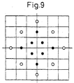
- Figure 9 is a view of a conventional signal constellation and is a signal constellation based on the V.29 recommendation.
- the signal point is not necessarily positioned at a center point of a lattice. Therefore, there are cases where the distance between signal points becomes larger, so the average power of the signal points of the eye pattern of the figure becomes 216.
- the S/N error rate may be improved by exactly 0.76 dB (theoretical value) and the peak factor can be improved by exactly 0.5 dB.
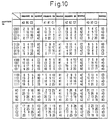
- Figure 10 is a view of numerical values for explaining the method of selection of signal points according to the present invention.
- the present TD is a signal point of the transmission data currently input to the ROM 61 (Fig. 7).
- the signal point of the present TD is inside the frame (Fig. 8)
- the signal point is sent to the receiving side as it is, so only a signal point present outside of the frame is displayed as the present TD shown in Fig. 10. That is, these are (A0, B0, C0) to (A3, B3, C3).
- the previous TD is shown at the left end of Fig. 10.
- the previous TD is the signal point output from the ROM 61 before the input of the present TD is input (one of 24 values) and is temporarily held in the register 62 (Fig. 8).
- the signal point of the previous TD at that time is considered to be (0000).
- the square distance (x 2 +y 2 ) of the signal point (0000) with A0 is 2
- the square distance with B0 is 9, and the square distance with C0 is 9.
- A0 giving the smallest square distance with respect to the signal point (0000) is selected at the ROM 61 and sent to the receiving side.
- the square distances shown in Pig. 10 are computed in accordance with the signal constellation of Fig. 8 in advance.
- the results of the computations are stored in advance in the ROM 61. Therefore, if the signal points of the present TD and the previous TD are given to the ROM 61 as addresses, the ROM 61 can instantaneously read the signal point giving the least square distance.
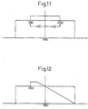
- Figure 11 is a view of the spectrum in the state where the energy near the carrier frequency increases.
- the abscissa indicates the frequency, while the ordinate indicates the energy.
- the energy of the portion of the +400/-400 Hz band (1250 Hz to 2050 Hz) increases with respect to the carrier frequency. That is, if the baud rate is 2400 Baud, as shown in Fig. 8, since the signal points of A, B, and C are arranged at 120° intervals from each other, there is a deflection width of +60°/-60°. This corresponds to the above +400/-400 Hz (2400+6).
- Figure 12 is a view of the spectrum after the spectrum of Fig. 11 passes through the filter (DE) 29.
- the transmission signal in the modem transmitter 2T passes through the deemphasis filter (DE) 29 with the spectrum shown in Fig. 11. With the spectrum shown in Fig. 11 as it is, however, the output from the filter 29 ends up in the state shown in Fig. 12.
- a -400 Hz frequency shift is applied to the output of the signal point generating circuit 24 (Fig. 2) by a frequency shifter and shifts the energy of transmission to the low band side.
- Figure 13 is a view of an example of a frequency shifter.
- this can be realized as a vector multiplier using a DSP.
- This is a circuit which multiplies a -400 Hz carrier with the digital baseband signal and obtains a frequency shifted output (OUT).
- This frequency shifter 35 may for example be provided at the ROT 25 as shown in Fig. 2.
- Figure 14 is a view of the spectrum when applying a frequency shift to the spectrum of Fig. 11. Therefore, the portion where the energy increases shifts to the 850 Hz to 1650 Hz band.
- the signal having the spectrum shown in Fig. 14 is passed through the deemphasis filter 29.
- Figure 15 is a view of a spectrum when a frequency shifted signal passes through the filter 29.
- the improvement (ii) is the mounting of the deemphasis filter (DE) in the modem transmitter 2T and the mounting of the emphasis filter (EMP) 41 in the modem receiver 2R.
- a deemphasis filter (DE) 29 having inverse characteristics from the filter characteristics of the preemphasis filter 11. of the radio transmitter 1T is inserted.
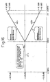
- Figure 16 is a view of the characteristics of the deemphasis filter and the emphasis filter in the modem of the present invention.
- the deemphasis filter 29 according to the present invention has inverse characteristics from the characteristics of the preemphasis filter 11 of the radio transmitter 1T (Fig. 21) in the range of 1.0 kHz to 3.0 kHz. In the range of 0.3 kHz to 1.0 kHz, however, the characteristics become flat ⁇ F>. This is because there is an upper limit in the signal level able to be input to the preemphasis filter 11 of the radio transmitter 1T and if the inverse characteristics of the preemphasis characteristics ⁇ 11> shown in Fig. 21 are given over the entire band range, the level of the signal in the low band would become particularly excessive. This is to prevent it.
- an emphasis filter (EMP) 41 having inverse characteristics from the characteristics of the deemphasis filter 32 of the radio receiver 1R is provided before the demodulator (DEM) 42.
- the characteristics of the deemphasis filter of the radio receiver 1R are shown by ⁇ 32> in Fig. 21, while the characteristics of the emphasis filter (41) of the modem receiver 2R are shown as ⁇ 41> in Fig. 16.
- the emphasis filter 41 of the modem receiver 2R according to the present invention like the deemphasis filter 29 of the modem transmitter 2T and as shown in Fig. 16, has flat characteristics ⁇ F> for the band of 0.3 kHz to 1,0 kHz.
- the improvement (i) is optimization of the carrier frequency.
- Figure 17 is a view for explaining the optimization of the carrier frequency according to the present invention.
- the top section shows the carrier frequency and transmission band of a V.29 modem
- the center section shows the carrier frequency and transmission band shifted in frequency according to the present invention
- the bottom section shows the carrier frequency and transmission band of a narrow band radio.
- the transmission band of the V.29 modem shown in the top section is 0.3 to 3.1 kHz (in Fig. 17, 0.32 to 3,08 kHz) and the center frequency is 1700 Hz.
- the transmission band of the narrow band radio shown in the bottom section is 0.30 to 3.00 kHz and the center frequency is 1650 Hz.
- the modem transmitter 2T is modulated and transmitted to the radio transmitter 1T by a carrier signal of 1650 Hz output from the carrier generating circuit (CRR) 28.
- the transmission band ends up protruding from the transmission band of a narrow band radio (0.3 to 3.00 kHz) by about +0.3/-0.3 kHz. A small deviation of this extent, however, does not obstruct practical data transmission that much. What is important here is to match the carrier frequencies.
- the modem receiver 2R conversely, the received signal of the center frequency of 1650 Hz output from the radio receiver 1R is demodulated by the carrier signal (frequency 1650 Hz), then the energy shifted to the low band at the transmission side is restored to its original state by the inverse frequency movement circuit (inverse ROT) 47.
- inverse ROT inverse frequency movement circuit
- Figure 18 is a view of the degree of improvement according to the present invention.
- the operating margin in a V.29 modem which had been -4.5 dB, can be made +5.5 dB and can sometimes be improved to 10.0 dB. Further, the required S/N ratio can be improved from the 23.0 dB of the past to 21.0 dB and the peak factor from 5.0 dB to 4.5 dB.
- the ROT unit 25 or the deemphasis unit 29 is provided at the modem transmitter 2T, while the inverse ROT unit 47 or emphasis unit 41 is provided the modem receiver 2R.
- This configuration considers the connection of a radio for general voice transmission to a modem. According to the concept of the present invention, however, it is clear that there is no particular reason why these characterizing portions (25, 29, 41, and 47) have to be provided in the modems (2T, 2R).
- a configuration removing the preemphasis circuit or deemphasis circuit originally provided at the radio side may also be selected.
- the present invention has as one of its features (iii) giving redundancy to the set of signal points at the outside of a signal constellation coordinate system with a large energy, not giving redundancy to the set of signal points having a small energy at the inside, and minimizing the amount of deviation between preceding and succeeding signal points for all signal points. Further, it has as a feature, when a redundant signal point is selected, the calculation of the amounts of deviation between a plurality (whole number more than 1) of signal points (A, B, and C) allocated for that signal point and a past signal point and selection of the signal point giving the minimum amount of deviation as the signal point of the transmission data TD.
- the present invention has one of its features the provision of a ROM, computing the amount of deviation among all signal points and storing the results of the computation in the ROM, reading out from the ROM and holding the output temporarily in a register, feeding this back to the input of the ROM as an address, and automatically selecting the signal point of the minimum amount of deviation.
- the present invention has as one of its features (ii) giving the modem filter characteristics for compensating for the characteristics of the radio so as to give frequency characteristics optimized for data transmission using a radio.
- the present invention has as one of its features (i) matching the demodulated carrier frequency of the modem with the center frequency of the transmission band of the radio.
- the present invention realizes a method of signal-point generation able to add redundancy to signal points to minimize the amount of deviation between signal points and to minimize the peak factor.
- the present invention it becomes possible to minimize the peak factor of a modem. Further, it becomes possible to improve the S/N error rate. Due to this, it is possible to broaden the dynamic range at the time of over 9600 bps high speed data transmission in a radio transmission path without a change of the characteristics of the radio, it is possible to secure a sufficient operating margin even if considering fading and becomes possible to achieve a practical system under conditions of the same level as those for 1200 bps.
Landscapes
- Engineering & Computer Science (AREA)
- Computer Networks & Wireless Communication (AREA)
- Signal Processing (AREA)
- Digital Transmission Methods That Use Modulated Carrier Waves (AREA)
- Cable Transmission Systems, Equalization Of Radio And Reduction Of Echo (AREA)
Applications Claiming Priority (3)
| Application Number | Priority Date | Filing Date | Title |
|---|---|---|---|
| JP29170498 | 1998-10-14 | ||
| JP10291704A JP2000124842A (ja) | 1998-10-14 | 1998-10-14 | 伝送装置および信号点発生方法 |
| PCT/JP1999/002889 WO2000022752A1 (fr) | 1998-10-14 | 1999-05-31 | Appareil de transmission et procede de generation de points de signal |
Publications (1)
| Publication Number | Publication Date |
|---|---|
| EP1122893A1 true EP1122893A1 (de) | 2001-08-08 |
Family
ID=17772329
Family Applications (1)
| Application Number | Title | Priority Date | Filing Date |
|---|---|---|---|
| EP99923857A Withdrawn EP1122893A1 (de) | 1998-10-14 | 1999-05-31 | Übertragungsgerät und verfahren zur signalpunkterzeugung |
Country Status (4)
| Country | Link |
|---|---|
| US (1) | US20010016015A1 (de) |
| EP (1) | EP1122893A1 (de) |
| JP (1) | JP2000124842A (de) |
| WO (1) | WO2000022752A1 (de) |
Cited By (2)
| Publication number | Priority date | Publication date | Assignee | Title |
|---|---|---|---|---|
| WO2004045180A1 (en) * | 2002-10-08 | 2004-05-27 | M/A-Com, Inc. | Apparatus, methods and articles of manufacture for pre-emphasis filtering of a modulated signal |
| US7340007B2 (en) | 2003-09-16 | 2008-03-04 | M/A-Com, Inc. | Apparatus, methods and articles of manufacture for pre-emphasis filtering of a modulated signal |
Families Citing this family (3)
| Publication number | Priority date | Publication date | Assignee | Title |
|---|---|---|---|---|
| KR100842775B1 (ko) * | 2007-02-13 | 2008-07-01 | 한국과학기술원 | 높은 속도의 통신을 위한 이단 등화기, 이단 등화 방법,수신기 및 통신 시스템 |
| US8654890B2 (en) * | 2011-12-14 | 2014-02-18 | Texas Instruments Incorporated | Adaptive real-time control of de-emphasis level in a USB 3.0 signal conditioner based on incoming signal frequency range |
| JP7687002B2 (ja) * | 2021-03-11 | 2025-06-03 | 横河電機株式会社 | 信号出力装置 |
Family Cites Families (6)
| Publication number | Priority date | Publication date | Assignee | Title |
|---|---|---|---|---|
| JPS6257311A (ja) * | 1985-09-05 | 1987-03-13 | Victor Co Of Japan Ltd | ノンリニアエンフアシス回路 |
| JPH0773192B2 (ja) * | 1986-05-30 | 1995-08-02 | 株式会社日立製作所 | 信号処理装置 |
| JPH0642644B2 (ja) * | 1986-12-05 | 1994-06-01 | 富士通株式会社 | 等化方式 |
| FR2637431B1 (fr) * | 1988-09-30 | 1990-11-09 | Labo Electronique Physique | Circuit de predistorsion adaptative |
| JP2656647B2 (ja) * | 1990-04-18 | 1997-09-24 | 株式会社日立製作所 | 信号処理方法とその装置 |
| JPH0477124A (ja) * | 1990-07-17 | 1992-03-11 | Nippon Hoso Kyokai <Nhk> | エンファシス・ディエンファシス装置 |
-
1998
- 1998-10-14 JP JP10291704A patent/JP2000124842A/ja active Pending
-
1999
- 1999-05-31 WO PCT/JP1999/002889 patent/WO2000022752A1/ja not_active Ceased
- 1999-05-31 EP EP99923857A patent/EP1122893A1/de not_active Withdrawn
-
2001
- 2001-04-12 US US09/833,963 patent/US20010016015A1/en not_active Abandoned
Non-Patent Citations (1)
| Title |
|---|
| See references of WO0022752A1 * |
Cited By (2)
| Publication number | Priority date | Publication date | Assignee | Title |
|---|---|---|---|---|
| WO2004045180A1 (en) * | 2002-10-08 | 2004-05-27 | M/A-Com, Inc. | Apparatus, methods and articles of manufacture for pre-emphasis filtering of a modulated signal |
| US7340007B2 (en) | 2003-09-16 | 2008-03-04 | M/A-Com, Inc. | Apparatus, methods and articles of manufacture for pre-emphasis filtering of a modulated signal |
Also Published As
| Publication number | Publication date |
|---|---|
| JP2000124842A (ja) | 2000-04-28 |
| WO2000022752A1 (fr) | 2000-04-20 |
| US20010016015A1 (en) | 2001-08-23 |
Similar Documents
| Publication | Publication Date | Title |
|---|---|---|
| US7577213B2 (en) | Hierarchical 8PSK performance | |
| JP4410307B2 (ja) | 通信方法及び通信システム | |
| US7016298B2 (en) | Signal transmission/reception system of orthogonal frequency division multiplexing | |
| US7349487B2 (en) | Nyquist filter and method | |
| US4817116A (en) | Digital radio communication system utilizing quadrature modulated carrier waves | |
| EP0609828A2 (de) | Adaptiver, signalangepasster Filter | |
| DE69934349T2 (de) | Pilotsignalsnübertragungstechnik und diesen verwendendes digitales Kommunikationssystem | |
| US5734681A (en) | Process and system for transferring vector signal with precoding for signal power reduction | |
| US5600676A (en) | Modulation scheme with low envelope variation for mobile radio by constraining a maximum modulus of a differential phase angle | |
| US7599446B2 (en) | Modulation and demodulation based on hierarchical modulation | |
| US6658067B1 (en) | Data transmission method and radio system | |
| US20010016015A1 (en) | Transmission apparatus and method of signal-point generation | |
| JPH06204907A (ja) | デジタル無線受信機 | |
| EP0122127B1 (de) | Radio-Kommunikationssystem | |
| US5231647A (en) | Modem comprising saw filters having opposite bassband delay characteristics | |
| US6009123A (en) | Process and system for transferring vector signal with precoding for signal power reduction | |
| US5826174A (en) | Method and apparatus for improving data transmission over a wireless system by optical spectrum positioning | |
| US7729441B2 (en) | Method and system for data transmission with decreased bit error rate | |
| WO1996013111A1 (en) | A qam constellation which is robust in the presence of phase noise; encoder and decoder for this constellation | |
| JP2861778B2 (ja) | 復調装置 | |
| JP3980017B2 (ja) | 送信装置及び通信方法 | |
| US20080031377A1 (en) | Method and system for data transmission with decreased bit error rate | |
| Dittmer | Advances in digitally modulated RF systems | |
| JP2793985B2 (ja) | 可変容量スペクトル拡散伝送装置 | |
| JP3311910B2 (ja) | 位相比較器及び復調器並びに通信装置 |
Legal Events
| Date | Code | Title | Description |
|---|---|---|---|
| PUAI | Public reference made under article 153(3) epc to a published international application that has entered the european phase |
Free format text: ORIGINAL CODE: 0009012 |
|
| 17P | Request for examination filed |
Effective date: 20010412 |
|
| AK | Designated contracting states |
Kind code of ref document: A1 Designated state(s): DE FR GB |
|
| STAA | Information on the status of an ep patent application or granted ep patent |
Free format text: STATUS: THE APPLICATION IS DEEMED TO BE WITHDRAWN |
|
| 18D | Application deemed to be withdrawn |
Effective date: 20031202 |