EP1122896A2 - Système de radiocommunication - Google Patents
Système de radiocommunication Download PDFInfo
- Publication number
- EP1122896A2 EP1122896A2 EP01102176A EP01102176A EP1122896A2 EP 1122896 A2 EP1122896 A2 EP 1122896A2 EP 01102176 A EP01102176 A EP 01102176A EP 01102176 A EP01102176 A EP 01102176A EP 1122896 A2 EP1122896 A2 EP 1122896A2
- Authority
- EP
- European Patent Office
- Prior art keywords
- transmission
- power control
- mobile terminal
- signal
- power
- Prior art date
- Legal status (The legal status is an assumption and is not a legal conclusion. Google has not performed a legal analysis and makes no representation as to the accuracy of the status listed.)
- Granted
Links
- 238000004891 communication Methods 0.000 title claims abstract description 44
- 230000005540 biological transmission Effects 0.000 claims abstract description 207
- 230000000153 supplemental effect Effects 0.000 claims abstract description 27
- 238000012544 monitoring process Methods 0.000 claims description 3
- 238000009792 diffusion process Methods 0.000 description 44
- 238000000034 method Methods 0.000 description 13
- 238000012545 processing Methods 0.000 description 13
- 238000010586 diagram Methods 0.000 description 8
- 230000003247 decreasing effect Effects 0.000 description 5
- 230000007423 decrease Effects 0.000 description 3
- 238000013459 approach Methods 0.000 description 2
- 238000010276 construction Methods 0.000 description 2
- 230000006866 deterioration Effects 0.000 description 1
Images


Classifications
-
- H—ELECTRICITY
- H04—ELECTRIC COMMUNICATION TECHNIQUE
- H04W—WIRELESS COMMUNICATION NETWORKS
- H04W52/00—Power management, e.g. Transmission Power Control [TPC] or power classes
- H04W52/04—Transmission power control [TPC]
- H04W52/30—Transmission power control [TPC] using constraints in the total amount of available transmission power
- H04W52/36—Transmission power control [TPC] using constraints in the total amount of available transmission power with a discrete range or set of values, e.g. step size, ramping or offsets
- H04W52/367—Power values between minimum and maximum limits, e.g. dynamic range
Definitions
- the present invention relates to a radio communication system for radio communication which comprises a base station and a mobile terminal, and is based on a CDMA system.
- An IS-95A system and an IS-95B system are well-known as such a radio communication system.
- a radio line which a mobile terminal uses for communication is called a traffic channel.
- necessary qualities of communication through communication channels must be at the lowest level so as to assure a line capacity.
- a fast power control is requested for, in particular, a reverse line.
- a power control signal "power control bit" is inserted to a forward traffic channel to receive signals from all mobile terminals at a base station with the same quality, thereby controlling transmission powers of the mobile terminals.
- the base station If the signal received by one base station has an insufficient-quality signal, the base station inserts "0" to the forward traffic channel as the power control bit and transmits it. If the signal received by one base station has an excessive-quality signal, the base station inserts "1" to the forward traffic channel as the power control bit and transmits it.
- the power control bit "0" When the power control bit "0" is received, the mobile terminal increases the transmission power. When the power control bit "1" is received, the mobile terminal decreases the transmission power. In the IS-95A system, because a maximum value of the transmission power of the mobile terminal is determined, the transmission power of the mobile terminal does not exceeds the maximum value if a state of the power control bit "0" continues.
- a plurality of traffic channels for data communication can be assigned to one mobile terminal. It is assumed that in the IS-95B system, an existing traffic channel used in the IS-95A system is called a fundamental channel and a traffic channel added for data communication is called a supplemental channel. One fundamental channel is necessarily assigned to the mobile terminal during communication. The maximum of seven supplemental channels can be assigned to the mobile terminal during communication.
- a diffusion code for the fundamental channel is different from that for the supplemental channel.
- the power control bit is inserted only to a forward fundamental channel.
- a diffusion unit for the fundamental channel and a plurality of diffusion units for the supplemental channel are set to one mobile terminal.
- the mobile terminal uses a plurality of traffic channels, thereby enabling the data communication.
- the fundamental channels and the reverse supplemental channel are assigned to a mobile terminal PS.
- a base station BS measures a receiving level or line quality of data transmitted from the mobile terminal PS through the fundamental channel. If the receiving level or line quality measured are compared with a target value and the compared result is then sufficient, the transmission power of the mobile terminal PS is controlled to decrease the transmission power. If the compared result is insufficient, the transmission power of the mobile terminal PS is controlled by using the power control bit to increase the transmission power.
- the base station BS If the mobile terminal PS is located far from the base station and the propagation loss of the radio line increases, the base station BS cannot receive the signal from the mobile terminal PS at the sufficient level or quality. In this case, the base station BS controls the transmission power of the mobile terminal PS to be increased by use of the power control bit to set the transmitted power to the sufficient receiving-level or receiving quality. Further, when the mobile terminal PS moves and the propagation loss of the radio line increases, the base station BS also controls the transmission power of the mobile terminal PS to be increased.
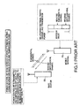
- the transmission power of the mobile terminal PS has the upper limit and the transmission power of the mobile terminal PS cannot be increased though the base station instructs the increase in transmission power, as shown in Fig. 2.
- the base station BS cannot receive the reverse signal from the mobile terminal PS. If such a state continues, a call of the mobile terminal PS is disconnected, the mobile terminal PS continues the transmission of the maximum transmission power to increase the interference with the reverse signal of other mobile terminals.
- a radio communication system includes a base station which transmits a data signal to a mobile terminal through a forward channel (forward fundamental channel) and also transmits one of a first power control signal (a power control bit having a value "1") indicating the positive of a received signal from the mobile terminal and a second power control signal (a power control bit having a value "0") indicating the negative of the received signal in accordance with the positive or negative of the received signal through the forward channel, and a mobile terminal which transmits a data signal to the base station through a first reverse channel (reverse fundamental channel) indicating the existing traffic channel and a second reverse channel indicating a traffic channel added for data communication and controls an operation to increase a transmission power of the data signal to be transmitted to the base station when the second power control signal is received.
- a forward channel forward fundamental channel
- the mobile terminal includes a receiving unit for receiving the first and second power control signals, a transmission power control unit for controlling a power of the transmission signal of the reverse channel based on the first and second power control signal which are received by the receiving unit, a transmission control unit for monitoring whether or not a value of the transmission power controlled by the transmission power control unit exceeds a predetermined maximum value (maximum transmission-power value) and for transmitting the data signal to the base station only through the first reverse channel (reverse fundamental channel) when the transmission-power value reaches the maximum value and the second power control signal is continuously received for a predetermined time.
- a predetermined maximum value maximum transmission-power value
- the transmission control unit has a counter for counting the number of the second power control signals to be continuously received by the receiving unit and transmits a signal through the first reverse channel when the counted value of the counter reaches a predetermined number.
- the transmission control unit also has a timer for counting a continuous detecting time of the maximum transmission-power value and transmits a signal through the first reverse channel when the timer counts a predetermined time.
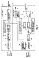
- Fig. 3 is a block diagram of one structure of a mobile terminal constructing a radio communication system of the present invention.
- the present radio communication system shows an example of the IS-95B specified by a TIA/EIA.
- the IS-95B system allocates two reverse communication channels (that is, one fundamental channel and one supplemental channel) to one mobile terminal, thereby executing fast data communication.
- the mobile terminal comprises a receiving unit 1 and a transmitting unit 2.
- the receiving unit 1 has a receiver 10, a demodulating unit 11, a reverse-diffusion unit 12, and a power control bit reading unit 3.
- the transmitting unit 2 has a transmission data control unit 21 including a counter 20A, a switch 22, diffusion units 23 and 24, an adding unit 25, a modulating unit 26, a transmitter 27, and a transmission power control unit 28.
- the receiver 10 in the receiving unit 1 converts a high-frequency signal which is transmitted from a base station, which will be described later, by a frequency, and outputs a signal which is frequency-converted to the demodulating unit 11.
- the demodulating unit 11 converts the frequency-converted signal to be outputted from the receiver 10 into a base band signal, and outputs the base band signal to the reverse-diffusion unit 12.
- the reverse-diffusion unit 12 multiplies the base band signal which is outputted by the demodulating unit 11 by a Walsh code for a forward fundamental channel, reversely diffuses the signal of the forward fundamental channel, and, thereafter, outputs data of the reverse-diffused forward fundamental channel to the power control bit reading unit 13.
- the power control bit reading unit 13 reads data of the reverse-diffused forward fundamental channel to be outputted by the demodulating unit 12 and, thereafter, outputs the reception data.
- the power control bit reading unit 13 reads a power control bit included in the data of the forward fundamental channel and outputs the read power control bit to the transmission data control unit 21 and the transmission power control unit 28 in the transmitting unit 1.
- the counter 20A in the transmission data control unit 21 counts the number of power control bits indicating "0" to be sequentially outputted by the power control bit reading unit 13.
- the transmission data control unit 21 controls the switch 22 and outputs transmission data only to the diffusion unit 23 to which a long code for the reverse fundamental channel is set.
- a transmission-power value of the mobile terminal to be outputted by the transmission power control unit 28 is equal to or less than a value obtained by dividing a maximum value by the number of traffic channels (the total of the number of fundamental channels and the number of supplemental channels)
- the transmission data control unit 21 switches the switch 22 and periodically outputs transmission data to the diffusion unit 23 to which the long code for the reverse fundamental channel is set or diffusion unit 24 to which the long code for the reverse supplemental channel is set.
- the diffusion unit 23 diffuses the transmission data to be outputted by the switch 22 by the long code for the reverse fundamental channel and outputs a base band signal to the adding unit 25.
- the adding unit 25 adds the base band signal to be outputted by the diffusion unit 23 and the base band signal to be outputted by the diffusion unit 24 and outputs the added base band signal to the modulating unit 26.
- the modulating unit 26 modulates the added base band signal which is outputted by the adding unit 25 and outputs a modulation signal to the transmitter 27.
- the transmitter 27 converts the modulation signal to be outputted by the modulating unit 26 into a high-frequency signal, adjusts a transmission power in accordance with the transmission power control signal to be outputted by the transmission power control unit 28, and transmits the high-frequency signal to a radio interval.
- the transmitter 27 always outputs a value of the transmission power of the mobile terminal to the transmission power control unit 28.
- the transmission power control unit 28 discriminates a value of the power control bit which is outputted by the power control bit reading unit 13 and outputs the transmission power control signal to the transmitter 27.
- the transmission power control unit 28 outputs a transmission-power value of the mobile terminal to be outputted by the transmitter 27 to the transmission data control unit 21.
- the transmission data control unit 28 in the transmitting unit 2 monitors the transmission power of the transmitter 27 and informs the transmission data control unit 21 on the value of the monitored transmission power.
- the transmission data control unit 21 monitors the transmission power of the mobile terminal to be outputted by the transmission power control unit 28 and the power control bit to be outputted by the power control bit reading unit 13.
- the transmission data control unit 21 controls the switch 22.
- the transmission data is outputted only to the diffusion unit 23 to which the long code for the reverse fundamental channel is set.
- the diffusion unit 23 diffuses and outputs the transmission data inputted. Since the transmission data is not inputted to the diffusion unit 24, the diffusion unit 24 outputs no data.
- the adding unit 25 adds data which is outputted by the diffusion unit 23 and the diffusion unit 24. However, no data is outputted by the diffusion unit 24. Therefore, an amplitude of the base band signal to be inputted to the modulating unit 26 is smaller than that in the case of using the two diffusion units 23 and 24 and performing communication through the two traffic channel, and the transmission power of the transmitter 27 is also decreased.
- the transmission power control unit 28 detects that the transmitter 27 transmits no signal having the maximum power and can increase the transmission power by the power control bit to be outputted by the power control bit reading unit 13. Consequently, all transmission powers of the mobile terminal do not change and, however, the transmission power per traffic channel can be increased. Although a communication speed is reduced, it is possible to reduce the number of disconnecting times of calls due to the deterioration of the reverse line.
- the mobile terminal can communicate data only through one traffic channel.
- the transmission power per channel can be increased, thereby preventing the disconnection of calls in the data communication.
- the radio communication system of the present invention comprises a base station BS and a mobile terminal PS as shown in Figs. 4 and 5.
- Figs. 4 and 5 show examples of the operations in the case in which two reverse communication channels (one fundamental channel and one supplemental channel) are assigned to the mobile terminal PS and fast data-communication is executed.
- a signal through the forward fundamental channel to be transmitted from the base station BS includes not only the communication data as mentioned above in Fig. 1 but also the signal (the above power control bit) for controlling the transmission power of the mobile terminal PS.
- the mobile terminal PS receives the signal through the forward fundamental channel to be transmitted by the base station BS.
- the signal received by the mobile terminal PS is frequency-converted by the receiver 10 shown in Fig. 3 as mentioned above, is further detected by the demodulating unit 11, and is reversely diffused by the diffusion unit 12.
- the power control bit reading unit 13 reads the power control bit among the reverse-diffused signals.
- the power control bit read is outputted to the transmission data control unit 21 and the transmission power control unit 28.
- the transmission power control unit 28 controls the transmitter 27 in accordance with the power control bit and adjusts the transmission power of the mobile terminal (if the power control bit is "0", the transmission power is increased and, if it is "1", the transmission power is decreased).
- the transmission data of the mobile terminal PS is distributed into the diffusion unit 23 and the diffusion unit 24 by the switch 22 controlled by the transmission data control unit 21.
- the distributed transmission-data is diffused as signals of the traffic channels (fundamental channel and supplemental channel).
- the transmission data diffused to the channels is added by the adding unit 25 and is modulated by the modulating unit 26. Thereafter, the modulated transmission-data is converted into the high-frequency signal and is transmitted by the transmitter 27.
- the signal transmitted by the mobile terminal PS is received to the base station BS.
- the base station BS measures the receiving level or line quality of the fundamental channel to be transmitted by the mobile terminal PS. If the receiving level or line quality is compared with a target value and the compared result is then sufficient, the base station BS controls the transmission power of the mobile terminal PS by using the power control bit to reduce the transmission power. If it is insufficient, the base station BS controls the transmission power of the mobile terminal PS by using the power control bit to raise the transmission power.
- the transmission power of the mobile terminal PS is normally controlled, the transmission power of the mobile terminal PS is smaller than the maximum value as mentioned above in Fig. 1. In this case, it is assumed that the transmission power of the fundamental channel is equal to that of the supplemental channel.
- the base station BS cannot receive the signal of the mobile terminal PS having the sufficient level or sufficient quality.
- the base station BS controls the transmission power of the mobile terminal PS to be increased so as to obtain the sufficient level or sufficient quality.
- the base station BS also instructs the increase in transmission power of the mobile terminal PS as mentioned in Fig. 2.
- the transmission power of the mobile terminal PS has the upper limit. Therefore, though the base station BS instructs the increase in transmission power, the mobile terminal PS cannot increase the transmission power. Consequently, the base station BS cannot receive the reverse signal from the mobile terminal PS.
- the transmission power of the mobile terminal PS becomes maximum as described in Fig. 2, and both the transmission power of the fundamental channel and the transmission power of the supplemental channel become half of the maximum transmission power.
- the transmission data control unit 21 starts to monitor the power control bit to be inputted by the power control bit reading unit 13.
- the transmission data control unit 21 switches the switch 22 and controls the transmission data to be transmitted through the fundamental channel as shown in Fig. 2.
- the diffusion unit 24 to which the long code for supplemental channel outputs no data.
- an amplitude of the base band signal to be inputted to the modulating unit 26 is reduced. Therefore, all powers to be transmitted by the transmitter 27 are also reduced and the transmitter 27 can increase the transmission power.
- the base station BS instructs the mobile terminal PS to sequentially raise the transmission power. In accordance therewith, the mobile terminal PS increases the transmission power. If the receiving level or line quality to be received by the base station BS becomes sufficient, it is possible to continue the communication without disconnecting the call. In this case, the transmission power of the fundamental channel can be increased to the half value of the maximum value or more as shown in Fig. 4.
- the mobile terminal PS is located far from the base station BS and communicates data only through the fundamental channel and, thereafter, the mobile terminal PS approaches the base station BS again and the propagation loss of the radio interval is reduced with reference to Fig. 5.
- the propagation loss is decreased.
- the transmission power control unit 28 instructs the transmission power to be reduced.
- the transmission data control unit 21 in the mobile terminal PS monitors the transmission-power value to be outputted by the transmission power control unit 28.
- the transmission data control unit 21 controls the switch 22 and distributes the transmission data to the diffusion unit 23 to which the long code for fundamental channel is set and the diffusion unit 24 to which the long code for supplemental channel is set. After distribution, the data communication starts again through the two traffic channels as shown in Fig. 5. In this case, the transmission power of the mobile terminal PS is smaller than the maximum value as shown in Fig. 5.
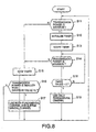
- Fig. 6 is a flowchart showing the operation of the transmission data control unit 21 of the mobile terminal PS shown in Fig. 3.
- reference numeral n in the flowchart in Fig. 6 denotes a value which is counted by the counter 20A in the transmission data control unit 21 in Fig. 3.
- the counted value n of the counter 20A is incremented by 1 when the transmission-power value from the mobile terminal PS to be inputted to the transmission data control unit 21 becomes maximum and the power control bit transmitted to the transmission data control unit 21 by the power control bit reading unit 13 is "0".
- the power control bit becomes "0".
- Reference numeral m shown in Fig. 6 denotes the aforementioned number of traffic channels assigned to the mobile terminal PS (the total of the number of fundamental channels and the number of supplemental channels).
- the transmission data control unit 21 determines whether or not the transmission-power value is the maximum value (step S1).
- the value n of the counter 20A is set to be "0" in step S4. It is determined whether or not the transmission-power value from the transmission power control unit 28 is smaller than the (maximum value/m) (i.e., a value obtained by dividing the maximum transmission-power value by the number of traffic channels (step S5).
- the processing routine returns to step S1 and the transmission-power value from the transmission power control unit 28 is then monitored. If the transmission-power value is smaller than the (maximum value/m) (if "Y" in step S5), the switch 22 is switched and the transmission data is periodically supplied to the diffusion unit 23 and the diffusion unit 24 (step 56). After a process for transmitting data to the base station BS, the processing routine returns to step S1 and the transmission-power value from the transmission power control unit 28 is monitored again.
- step S2 If the transmission-power value from the transmission power control unit 28 becomes maximum and the determination in step S1 becomes "Y”, the power control bit read by the power control bit reading unit 13 is inputted (step S2). It is determined whether or not the inputted power control bit is "0" (step S3). Herein, if the power control bit is "1" and the determination in step S3 is "N”, the value n of the counter 20A is set to be "0” (step S4). Thereafter, it is determined whether or not the transmission-power value from the transmission power control unit 28 is smaller than the (maximum value/m) (step S5).
- the switch 22 is switched, thereby performing a process for periodically supplying the transmission data to the diffusion unit 23 and the diffusion unit 24 (in other words, transmitting process using both the fundamental channel and the supplemental channel (step S6).
- step S7 if the inputted power control bit is "0" and the determination in step S3 is "Y", the counted value n of the counter 20A is incremented by 1 (step S7). Subsequently, it is determined whether or not the counted value n is equal to or more than the threshold N (step S8). If the threshold N is larger than the counted value n of the counter 20A, the processing routine returns to step S2 and the power control bit "0" which is read by the power control bit reading unit 13 is sequentially inputted and counted. When the counted value n of the counter 20A is larger than the threshold N, the switch 22 is switched (step S9).
- step S1 the transmission-power value from the transmission power control unit 28 is inputted again, and the inputted value is monitored.
- step S3 When the transmission-power value from the transmission power control unit 28 becomes maximum, the power control bit "0" is sequentially inputted.
- the processing routine proceeds to the above processes subsequent to step S4. That is, after the value n of the counter 20A is set to be "0", it is determined whether or not the transmission-power value from the transmission power control unit 28 is smaller than the (maximum value/m) in step S5. If the transmission-power value is smaller than the (maximum value/m), the switch 22 is switched in step S6, thereby executing the process for periodically supplying the transmission data to the diffusion unit 23 and the diffusion unit 24. The processing routine returns to step S1. If the transmission-power value is not smaller than the (maximum value/m), the processing routine promptly returns to step S1.
- the transmission data control unit 21 inputs the power control bit read by the power control bit reading unit 13. If the counted value n of the counter 20A for counting the power control bit "0" exceeds the threshold N, the transmission of data using the reverse supplemental channel is stopped. By switching to the data communication using only the reverse fundamental channel, the maximum transmission power of the reverse fundamental channel is increased.
- the base station BS can receive the data of the fundamental channel at the sufficient receiving level and line quality. Therefore, it is possible to reduce the disconnection ratio of calls of the mobile terminal PS which is communicating the data.
- the base station BS does not receive the signal of the reverse fundamental channel and the reverse supplemental channel at the sufficient receiving level or sufficient line quality, by preventing the continuous transmission of the mobile terminal PS at the maximum transmission power using a plurality of traffic channels, it is possible to reduce the interference with the reverse signal to be supplied to another mobile terminal.
- Fig. 7 is a block diagram showing a mobile terminal PS according to a second embodiment of the present invention.
- the mobile terminal PS shown in Fig. 7 is different from the mobile terminal PS in Fig. 3 in that the counter 20A is deleted from the transmission data control unit 21 in the mobile terminal PS shown in Fig. 3 and, in place thereof, a timer 20B is provided. Except therefor, the mobile terminal PS in Fig. 7 is the same as that of the first embodiment.
- the timer 20B of the transmission data control unit 21 When the transmission-power value of the mobile terminal PS to be inputted by the transmission power control unit 28 becomes maximum, the timer 20B of the transmission data control unit 21 operates. When the timer 20B becomes time-up, the transmission data control unit 21 switches 22 and connects the transmission data only to the diffusion unit 23 to which the long code for the reverse fundamental channel is set. Thereby, the data transmission starts by using only the fundamental channel.
- the transmission data control unit 21 switches the switch 22 and periodically supplies the transmission data to the diffusion unit 23 to which the long code for the reverse fundamental channel is set or diffusion unit 24 to which the long code for the reverse supplemental channel is set.
- the transmission data control unit 21 determines whether or not the transmission-power value is maximum (step S11). If the transmission-power value is not maximum, the timer 20A stops (step S15) and it is determined whether or not the transmission-power value inputted by the transmission power control unit 28 is smaller than the (maximum value/m) (step S16). If it is determined that the transmission-power value is not smaller than the (maximum value/m), the processing routine returns to step S11.
- the transmission data control unit 21 inputs the transmission-power value from the transmission power control unit 28 again and determines whether or not the transmission-power value is maximum. If the transmission-power value from the transmission power control unit 28 is smaller than the maximum value/m ("Y" in step S16), the switch 22 is switched (step S17), thereby executing a transmitting process using both the fundamental channel and the supplemental channel for periodically supplying the transmission data to the diffusion unit 23 and the diffusion unit 24. Thereafter, the processing routine returns to step S11.
- step S11 If the transmission-power value from the transmission power control unit 28 is inputted and the transmission-power value becomes maximum ("Y" in step S11), the initialization to set an initial value to the timer 20B is performed (step S12). The timer 20B starts and a value of the timer 20B is subtracted (step S13). The transmission-power value is sequentially inputted by the transmission power control unit 28 and it is determined whether or not the transmission-power value sequentially becomes maximum (step S14).
- step S15 it is determined whether or not the transmission-power value inputted by the transmission power control unit 28 is smaller than the (maximum value/m) (step S16). If the transmission-power value is not smaller than the (maximum value/m), the processing routine returns to step S11. That is, the transmission-power value is inputted again by the transmission power control unit 28 and it is monitored whether or not the transmission-power value becomes maximum. If the transmission-power value is smaller than (maximum value/m) ("Y" in step S16), the switch 22 is switched, thereby performing a process for periodically supplying the transmission data to the diffusion unit 23 and the diffusion unit 24 (step S17). Thereafter, the processing routine returns to step S11.
- step S14 If the transmission-power value inputted by the transmission power control unit 28 sequentially becomes maximum ("Y" in step S14), it is determined whether or not the value of the timer 20B is "0" as a result of the subtraction starting from step S13 (step S18).
- step S14 If the value of the timer 20B is not "0", the transmission-power value from the transmission power control unit 28 is sequentially inputted and it is determined whether or not the transmission-power value becomes maximum (step S14), It is determined whether or not the value of the timer 20B is "0" (step S18). This determination is repeated (step S14 and step S18).
- step S18 If the value of the timer 20B is "0" while the transmission-power value from the transmission power control unit 28 becomes maximum and the determination whether or not the value of the timer 20B is "0" in step S18 is "Y”, the switch 22 is switched (step S19) and the transmission data is supplied only to the diffusion unit 23, thereby performing a process for transmitting the transmission data to the base station BS (in other words, transmitting process using only the fundamental channel). Thereafter, the processing routine returns to step S11 and the transmission-power value from the transmission power control unit 28 is inputted again and is monitored.
- the transmission power control unit 28 reduces the transmission power and, therefore, the processing routine shifts to the above-mentioned processes subsequent to step S15.
- the mobile terminal PS stops the transmission of data using the reverse supplemental channel and switches the operation to the data transmission using only the reverse fundamental channel.
- the mobile terminal comprises a receiving unit for receiving the first and second power control signals, a transmission power control unit for controlling a power of the transmission signal of the reverse channels based on the first or second power control signal which is received, and a transmission control unit for transmitting the signal through the first reverse channel when the receiving unit receives the second power control signal continuously for a predetermined time in the case in which the maximum value of the transmission power is detected. Therefore, even when the mobile terminal during data communication is not
- the transmission control unit has a counter for counting the number of the second power control signals to be continuously received by the receiving unit, and also transmits a signal through the first reverse channel when the counted value of the counter reaches a predetermined value.
- the transmission data is transmitted through the first reverse channel, thereby reducing the disconnection ratio of calls of the mobile terminal when the propagation loss of the radio line increases.
- the transmission control unit also has a timer for counting a continuous detecting time of the maximum transmission-power value and also transmits a signal through the first reverse channel when the timer counters a predetermined time. Therefore, if the disconnection ratio of calls of the mobile terminal is reduced when the propagation loss of the radio line increases, the radio communication system can also be realized with the simple construction.
Landscapes
- Engineering & Computer Science (AREA)
- Computer Networks & Wireless Communication (AREA)
- Signal Processing (AREA)
- Mobile Radio Communication Systems (AREA)
Applications Claiming Priority (2)
| Application Number | Priority Date | Filing Date | Title |
|---|---|---|---|
| JP2000025128 | 2000-02-02 | ||
| JP2000025128A JP2001218253A (ja) | 2000-02-02 | 2000-02-02 | 無線通信システム |
Publications (3)
| Publication Number | Publication Date |
|---|---|
| EP1122896A2 true EP1122896A2 (fr) | 2001-08-08 |
| EP1122896A3 EP1122896A3 (fr) | 2005-06-08 |
| EP1122896B1 EP1122896B1 (fr) | 2007-01-24 |
Family
ID=18551028
Family Applications (1)
| Application Number | Title | Priority Date | Filing Date |
|---|---|---|---|
| EP01102176A Expired - Lifetime EP1122896B1 (fr) | 2000-02-02 | 2001-02-02 | Système de radiocommunication |
Country Status (7)
| Country | Link |
|---|---|
| US (1) | US6879839B2 (fr) |
| EP (1) | EP1122896B1 (fr) |
| JP (1) | JP2001218253A (fr) |
| KR (1) | KR20010078271A (fr) |
| CN (1) | CN1316841A (fr) |
| BR (1) | BR0100626A (fr) |
| DE (1) | DE60126166T2 (fr) |
Cited By (2)
| Publication number | Priority date | Publication date | Assignee | Title |
|---|---|---|---|---|
| EP2160063A1 (fr) * | 2008-08-29 | 2010-03-03 | Gemplus | Maîtrise de la fiabilité et/ou du périmètre d'une connexion radiofréquence |
| EP1530307A4 (fr) * | 2002-09-19 | 2012-06-06 | Panasonic Corp | Procede de commande de puissance d'emission et dispositif de station de base |
Families Citing this family (14)
| Publication number | Priority date | Publication date | Assignee | Title |
|---|---|---|---|---|
| KR100386562B1 (ko) * | 1999-11-01 | 2003-06-02 | 엘지전자 주식회사 | 순방향 공통 채널의 전력 제어 방법 |
| US7120134B2 (en) * | 2001-02-15 | 2006-10-10 | Qualcomm, Incorporated | Reverse link channel architecture for a wireless communication system |
| JP4005796B2 (ja) * | 2001-11-30 | 2007-11-14 | 富士通株式会社 | 電力制御回路および無線送信装置 |
| JP2004056478A (ja) | 2002-07-19 | 2004-02-19 | Fujitsu Ltd | 送信電力制御支援装置、無線装置および無線端末装置 |
| US8422434B2 (en) | 2003-02-18 | 2013-04-16 | Qualcomm Incorporated | Peak-to-average power ratio management for multi-carrier modulation in wireless communication systems |
| JP4194091B2 (ja) * | 2003-09-02 | 2008-12-10 | ソニー・エリクソン・モバイルコミュニケーションズ株式会社 | 無線通信システムおよび無線通信装置 |
| US8175031B2 (en) * | 2004-11-18 | 2012-05-08 | Telefonaktiebolaget Lm Ericsson (Publ) | Method and apparatus for supporting packet data services in service area boundary regions |
| DE102004061905A1 (de) * | 2004-12-22 | 2006-09-14 | Siemens Ag | Verfahren zur Übertragung von Datenpaketen |
| CN102595584B (zh) * | 2005-09-21 | 2015-07-22 | Lg电子株式会社 | 在多载波无线系统中建立附加反向链路载波 |
| JP4905007B2 (ja) * | 2006-09-12 | 2012-03-28 | 富士通株式会社 | 無線通信システムにおける上り通信方法及び無線端末 |
| CN101083496B (zh) * | 2007-07-17 | 2010-10-27 | 华为技术有限公司 | 同一功放中载波间功率分配方法及其系统 |
| JP4977543B2 (ja) * | 2007-07-20 | 2012-07-18 | 日本電気通信システム株式会社 | 制御装置、制御システム、制御方法及び制御プログラム |
| US8305947B2 (en) | 2010-02-12 | 2012-11-06 | Intel Corporation | Minimizing power consumption in a network device |
| US9131432B2 (en) * | 2013-02-05 | 2015-09-08 | Qualcomm Incorporated | Method and apparatus for efficient and dynamic system reselection procedure for M2M stationary devices |
Family Cites Families (11)
| Publication number | Priority date | Publication date | Assignee | Title |
|---|---|---|---|---|
| US6137789A (en) | 1997-06-26 | 2000-10-24 | Nokia Mobile Phones Limited | Mobile station employing selective discontinuous transmission for high speed data services in CDMA multi-channel reverse link configuration |
| US6393005B1 (en) * | 1997-06-27 | 2002-05-21 | Nec Corporation | Method of controlling transmitting power of a base station in a CDMA mobile communication system |
| JP3393363B2 (ja) | 1997-10-08 | 2003-04-07 | 沖電気工業株式会社 | 送信電力制御方法 |
| US6389296B1 (en) | 1997-10-08 | 2002-05-14 | Oki Electric Industry Co., Ltd. | Transmission power control method |
| JP3090109B2 (ja) * | 1997-11-18 | 2000-09-18 | 日本電気株式会社 | 送信電力制御方法および通信装置 |
| JP3755704B2 (ja) * | 1997-12-27 | 2006-03-15 | ソニー株式会社 | 送信電力制御方法、基地局装置及び通信端末装置 |
| US6700881B1 (en) * | 1998-03-02 | 2004-03-02 | Samsung Electronics Co., Ltd. | Rate control device and method for CDMA communication system |
| AU4656899A (en) * | 1998-07-13 | 2000-02-01 | Samsung Electronics Co., Ltd. | Power control device and method for reverse link common channel in mobile communication system |
| KR100278307B1 (ko) * | 1998-11-24 | 2001-01-15 | 이계철 | 전력제어 명령의 상태 천이를 이용한 단말기의 전력제어 장치및 그 동작 방법 |
| US6490460B1 (en) * | 1998-12-01 | 2002-12-03 | Qualcomm Incorporated | Forward and reverse link power control using position and mobility information |
| JP2001160776A (ja) * | 1999-12-01 | 2001-06-12 | Nec Corp | 送信電力制御周期の設定方法、送信電力制御周期設定装置および送信電力制御周期設定システム |
-
2000
- 2000-02-02 JP JP2000025128A patent/JP2001218253A/ja active Pending
-
2001
- 2001-02-01 US US09/774,635 patent/US6879839B2/en not_active Expired - Fee Related
- 2001-02-02 EP EP01102176A patent/EP1122896B1/fr not_active Expired - Lifetime
- 2001-02-02 DE DE60126166T patent/DE60126166T2/de not_active Expired - Lifetime
- 2001-02-02 KR KR1020010005017A patent/KR20010078271A/ko not_active Ceased
- 2001-02-02 BR BR0100626-6A patent/BR0100626A/pt not_active IP Right Cessation
- 2001-02-02 CN CN01102337A patent/CN1316841A/zh active Pending
Cited By (3)
| Publication number | Priority date | Publication date | Assignee | Title |
|---|---|---|---|---|
| EP1530307A4 (fr) * | 2002-09-19 | 2012-06-06 | Panasonic Corp | Procede de commande de puissance d'emission et dispositif de station de base |
| EP2160063A1 (fr) * | 2008-08-29 | 2010-03-03 | Gemplus | Maîtrise de la fiabilité et/ou du périmètre d'une connexion radiofréquence |
| WO2010023061A1 (fr) * | 2008-08-29 | 2010-03-04 | Gemalto Sa | Maitrise de la fiabilité et/ou du périmètre d'une connexion radiofréquence |
Also Published As
| Publication number | Publication date |
|---|---|
| JP2001218253A (ja) | 2001-08-10 |
| CN1316841A (zh) | 2001-10-10 |
| US20010011011A1 (en) | 2001-08-02 |
| BR0100626A (pt) | 2001-09-04 |
| KR20010078271A (ko) | 2001-08-20 |
| EP1122896B1 (fr) | 2007-01-24 |
| EP1122896A3 (fr) | 2005-06-08 |
| DE60126166D1 (de) | 2007-03-15 |
| DE60126166T2 (de) | 2007-06-06 |
| US6879839B2 (en) | 2005-04-12 |
Similar Documents
| Publication | Publication Date | Title |
|---|---|---|
| EP1122896B1 (fr) | Système de radiocommunication | |
| EP1001556B1 (fr) | Commande de la puissance de transmission dans un système CDMA capable de prévenir la déconnexion d'appel et la dégradation de la capacité d'abonnés | |
| CA2205714C (fr) | Methode de commande de puissances d'emission au moment du transfert dans un systeme de communication mobile amdc | |
| US5930242A (en) | Transmitting power control method and apparatus | |
| KR100292900B1 (ko) | 간섭없이각기지국에서송신전력을제어할수있는부호분할다중접속통신시스템 | |
| EP0887948B1 (fr) | Contrôle de la puissance et services de données dans des réseaux CDMA | |
| KR100243425B1 (ko) | 씨디엠에이 무선가입자망 시스템의 순방향 트래픽 채널 전력제어 방법 및 장치 | |
| AU700705B2 (en) | Communicating on a direct mode channel | |
| KR100389480B1 (ko) | 트래픽과 송신전력에 의거한 전송속도의 변화를 포함하는이동통신 제어 | |
| US6775558B1 (en) | Accessory interface within a multiple channel radio apparatus | |
| EP1738539B1 (fr) | Controle de charge dans des systemes de communication a origines multiples et destination unique d'un support partage | |
| KR20000029416A (ko) | 멀티캐스트 통신 시스템 및 멀티캐스트 채널을 포함한셀룰러 이동통신 시스템 | |
| KR100433899B1 (ko) | 부호분할다중접속 이동통신시스템에서 소프트 핸드오버결정장치 및 방법 | |
| EP1555766A2 (fr) | Système et procédéde de communication mobile à AMRC en considération l'évanouissement | |
| EP1414261B1 (fr) | Système cellulaire | |
| EP0893890A2 (fr) | Emetteut/récepteur CDMA et contrôle de la puissance d'émission dans un système de communication mobile | |
| CA2450458A1 (fr) | Systeme et methode de coordination de commande d'alimentation de canal de maintenance sans fil | |
| US6873626B2 (en) | Control system, control method, and radio network controller preferably used for the system and method | |
| GB2356322A (en) | Method of determining communications mode | |
| KR101158708B1 (ko) | 전송 전력 제어 방법, 통신 시스템 및 제 1 국 | |
| FI106665B (fi) | Menetelmä ja järjestely lähetystehon määrittämiseksi matkaviestimessä | |
| US7072619B2 (en) | Transmission-power control assisting apparatus for improved transmission-power control of a radio transmitter | |
| EP0999657B1 (fr) | Commande de la puissance de transmission dans un système CDMA capable de prévenir la déconnexion d'appel et la dégradation de la capacité d'abonnés | |
| US6370387B1 (en) | Cellular telecommunication system with macrodiversity mode | |
| US7558236B2 (en) | Communication method and system for improving control signal receiving quality during handover |
Legal Events
| Date | Code | Title | Description |
|---|---|---|---|
| PUAI | Public reference made under article 153(3) epc to a published international application that has entered the european phase |
Free format text: ORIGINAL CODE: 0009012 |
|
| AK | Designated contracting states |
Kind code of ref document: A2 Designated state(s): AT BE CH CY DE DK ES FI FR GB GR IE IT LI LU MC NL PT SE TR |
|
| AX | Request for extension of the european patent |
Free format text: AL;LT;LV;MK;RO;SI |
|
| PUAL | Search report despatched |
Free format text: ORIGINAL CODE: 0009013 |
|
| AK | Designated contracting states |
Kind code of ref document: A3 Designated state(s): AT BE CH CY DE DK ES FI FR GB GR IE IT LI LU MC NL PT SE TR |
|
| AX | Request for extension of the european patent |
Extension state: AL LT LV MK RO SI |
|
| RIC1 | Information provided on ipc code assigned before grant |
Ipc: 7H 04B 7/005 A |
|
| 17P | Request for examination filed |
Effective date: 20050502 |
|
| AKX | Designation fees paid |
Designated state(s): DE GB |
|
| GRAP | Despatch of communication of intention to grant a patent |
Free format text: ORIGINAL CODE: EPIDOSNIGR1 |
|
| GRAS | Grant fee paid |
Free format text: ORIGINAL CODE: EPIDOSNIGR3 |
|
| GRAA | (expected) grant |
Free format text: ORIGINAL CODE: 0009210 |
|
| AK | Designated contracting states |
Kind code of ref document: B1 Designated state(s): DE GB |
|
| REG | Reference to a national code |
Ref country code: GB Ref legal event code: FG4D |
|
| REF | Corresponds to: |
Ref document number: 60126166 Country of ref document: DE Date of ref document: 20070315 Kind code of ref document: P |
|
| PLBE | No opposition filed within time limit |
Free format text: ORIGINAL CODE: 0009261 |
|
| STAA | Information on the status of an ep patent application or granted ep patent |
Free format text: STATUS: NO OPPOSITION FILED WITHIN TIME LIMIT |
|
| 26N | No opposition filed |
Effective date: 20071025 |
|
| PGFP | Annual fee paid to national office [announced via postgrant information from national office to epo] |
Ref country code: DE Payment date: 20100211 Year of fee payment: 10 Ref country code: GB Payment date: 20100202 Year of fee payment: 10 |
|
| GBPC | Gb: european patent ceased through non-payment of renewal fee |
Effective date: 20110202 |
|
| REG | Reference to a national code |
Ref country code: DE Ref legal event code: R119 Ref document number: 60126166 Country of ref document: DE Effective date: 20110901 |
|
| PG25 | Lapsed in a contracting state [announced via postgrant information from national office to epo] |
Ref country code: GB Free format text: LAPSE BECAUSE OF NON-PAYMENT OF DUE FEES Effective date: 20110202 |
|
| PG25 | Lapsed in a contracting state [announced via postgrant information from national office to epo] |
Ref country code: DE Free format text: LAPSE BECAUSE OF NON-PAYMENT OF DUE FEES Effective date: 20110901 |