EP1122995B9 - Automatische höhensteuerung für schlegler mit nachköpfer von wurzelfruchterntemaschinen - Google Patents
Automatische höhensteuerung für schlegler mit nachköpfer von wurzelfruchterntemaschinen Download PDFInfo
- Publication number
- EP1122995B9 EP1122995B9 EP99957928A EP99957928A EP1122995B9 EP 1122995 B9 EP1122995 B9 EP 1122995B9 EP 99957928 A EP99957928 A EP 99957928A EP 99957928 A EP99957928 A EP 99957928A EP 1122995 B9 EP1122995 B9 EP 1122995B9
- Authority
- EP
- European Patent Office
- Prior art keywords
- flailer
- feeler
- automatic height
- controller according
- housing
- Prior art date
- Legal status (The legal status is an assumption and is not a legal conclusion. Google has not performed a legal analysis and makes no representation as to the accuracy of the status listed.)
- Expired - Lifetime
Links
- 241001124569 Lycaenidae Species 0.000 title abstract description 5
- 238000003306 harvesting Methods 0.000 claims abstract description 7
- 235000016068 Berberis vulgaris Nutrition 0.000 claims description 15
- 241000335053 Beta vulgaris Species 0.000 claims description 15
- 210000002105 tongue Anatomy 0.000 claims 8
- 230000006978 adaptation Effects 0.000 claims 1
- 238000003801 milling Methods 0.000 description 3
- 210000003739 neck Anatomy 0.000 description 3
- 235000011293 Brassica napus Nutrition 0.000 description 2
- 240000008100 Brassica rapa Species 0.000 description 2
- 235000000540 Brassica rapa subsp rapa Nutrition 0.000 description 2
- 235000013399 edible fruits Nutrition 0.000 description 2
- 238000000034 method Methods 0.000 description 2
- 239000000523 sample Substances 0.000 description 2
- 238000006243 chemical reaction Methods 0.000 description 1
- 230000035613 defoliation Effects 0.000 description 1
- 230000001419 dependent effect Effects 0.000 description 1
- 238000005259 measurement Methods 0.000 description 1
- 239000000700 radioactive tracer Substances 0.000 description 1
- 230000001105 regulatory effect Effects 0.000 description 1
- 230000000630 rising effect Effects 0.000 description 1
- 230000001953 sensory effect Effects 0.000 description 1
Images
Classifications
-
- A—HUMAN NECESSITIES
- A01—AGRICULTURE; FORESTRY; ANIMAL HUSBANDRY; HUNTING; TRAPPING; FISHING
- A01D—HARVESTING; MOWING
- A01D23/00—Topping machines
- A01D23/02—Topping machines cutting the tops before being lifted
-
- A—HUMAN NECESSITIES
- A01—AGRICULTURE; FORESTRY; ANIMAL HUSBANDRY; HUNTING; TRAPPING; FISHING
- A01D—HARVESTING; MOWING
- A01D23/00—Topping machines
- A01D23/02—Topping machines cutting the tops before being lifted
- A01D2023/022—Rotatable cleaning devices, e.g. brushes, for removing the rests of vegetal material on the root-crops not yet harvested
-
- A—HUMAN NECESSITIES
- A01—AGRICULTURE; FORESTRY; ANIMAL HUSBANDRY; HUNTING; TRAPPING; FISHING
- A01D—HARVESTING; MOWING
- A01D23/00—Topping machines
- A01D23/02—Topping machines cutting the tops before being lifted
- A01D2023/024—Devices with fix blades for topping
Definitions
- the invention relates to an automatic height control according to the preamble of Claim 1, and in particular on an automatic height control for beet harvesters.
- the sledge with which the working height, up to which the leaves of the root crops are removed set that a leading feeler wheel and thus that connected to the feeler wheel Schleglergeophus is adjusted in height, so that an approximately middle height position the Schleglerwelle is reached. Since the adjustment of the support or feeler wheel relatively is cumbersome, a mechanical adjustment of the Schlegler altar must at least for a portion of the stock can be considered sufficient.
- the height adjustment of the jockey wheel is based on empirical values or estimated values of the operator. In particular, this can be due to short-term changes in the beet crop not be received.
- a topper connects to the topper, with its tactile elements and its Cutting a head slice from the root crop.
- the repopper To the loss To keep root fruit mass as low as possible, the repopper must be at his working height be adjusted to the height of the root crop heads, and the comb of the Nachkmürs must palpate the top of the root crop.
- the height adjustment of the Schleglergeophuses or Schlegler tool, and the height adjustment of the Nachkmürs takes place through separate adjustment processes and adjustment devices.
- a device for defoliation and milling of beets before lifting which consists of a first rotor equipped with flails for processing the leaves and a second rotor equipped with milling knives for processing the root neck of the root crop.
- the first rotor consists of a single shaft rising in the direction of travel, which can be pivoted about a horizontal axis in the area of its upper end and can be adjusted in relation to the desired minimum distance of the lower end from the ground by means of a locking device which only limits its pivoting downwards.
- the second rotor which can also be pivoted about a horizontal axis, is positively controlled with respect to its respective height distance from the root necks to be machined by a button which scans these root necks.
- the second rotor is designed as a drum, the drum axis of which lies in the direction of travel, the milling cutters being arranged from the drum shell.
- the object of the invention is to carry out a height control of the topper shaft or the topper housing automatically, so that the height position of the topper shaft adjusts itself automatically and continuously without mechanical or manual adjustment to the beet stock, and thus a corresponding height-adjustable support wheel for the topper housing can be omitted.
- a support wheel for height adjustment of the Schleglergeophuses and thus completely to adjust the working height of the flail tool can be dispensed with and a fully automatic height adjustment of the topper in connection and is achieved analogously with the height adjustment of the secondary head, by the Height adjustment of the feeler device for analog height adjustment of the Schleglergeophuses is used.
- the feeler on the dopper is one of them Such machines, in particular beet harvesters, already existing and necessary device with which the cutting height or head thickness of the root crops is set.
- the feeler touches the top surface of the one that has already been ground Fruit and adapts its height position to the stock so that the head position the amount depends on the excess of the root crop over the ground is constantly changing.
- the height adjustment of the feeler on the repopper thus determines the height of the top slice, which is separated from the root crop.
- the height change transferred to the topper in proportion to the Schleglergeophuse whereby It must be taken into account that the Schlegler tool remove the leaves of the root crops and the working level a few centimeters above the top surface of the root crop must be set while the working level on the repopper by a few Centimeter (corresponding to the head plate) is lower.
- the tactile surface on the Turnip is thus twofold, namely once for the adjustment of the head knife and secondly used for setting the Schlegleriereiere.
- the distance by which the touch element of the post-head changes when the height changes of the stock is moved by an electronic switching device, e.g. a potentiometer control, recorded, which converts the route into an electrical signal and via this electrical signal a drive device, e.g. a working cylinder, acts on the Schleglergephinus proportional to the distance that the Touch element has moved in height, raises or lowers, so that the delivery the Schlegler tool is set analogously to the root crops.
- an electronic switching device e.g. a potentiometer control
- a drive device e.g. a working cylinder
- the conversion of the height adjustment of the feeler element on the repopper to electrical Signals to move the Schleglergecher correspondingly can instead via a potentiometer control also via other conventional control devices z.
- the mechanical connection between the repopper advantageously has and the Schleglergeophuse the shape of a parallelogram, one side with the Touch element of the head and its other side firmly connected to the Schleglergecher is, the change in the parallelogram for lifting the Schleglergeophus by means of a working cylinder which changes the parallelogram.
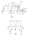
- the Schlegerergeophen 1 receives a Schleglerwelle 2 with Schleglerwerkmaschine 3, the the beets 4 from the leaves 5 at a distance of a few centimeters above the top surface 6 of the turnip 4 cuts off.
- the effective area of the Schleglerwerkmaschine 3, d. H. the Schlegler altar, is designated by 7.
- Jockey wheel 8, support 9 and support arm 10 are omitted in the case of the present invention.
- the repopper 11 has a feeler element 12 with an associated head knife 13.
- the Probe element 12 with knife 13 is designed to be height-adjustable, as indicated by arrow 14.
- the feeler element 12 slides over the beet crop or over the ground Beets 4, so that the vertical movement of the feeler element from the height of the beet depends on the ground and changes according to the stock height.
- the height movement or the distance by which the sensing element 12 moves is on a electrical or electronic switching device 15, which the covered Converts distance into electrical signals.
- a potentiometer control can be used for this purpose be used.
- the output from the switching device 15 Electrical signals are used to act on a drive or adjusting cylinder 16, which actuates a carrier 18 in the illustration according to FIG. 1, which has one end attached to the Schleglergeophuse 1 and with the other end to the machine frame 17 is.
- the repopper 11 is the button element 12 and the head knife 13, via a parallelogram guide 19 and a carrier 20 connected to the Schleglergkoruses 1.
- the carrier 20 is in connection with a lifting rod 21 of a lifting cylinder 22, the entire repulping 11 in the Height adjusted so that a basic setting of the working height of the Nachkmürs is achieved.
- the copter 11 has an angle sensor 23, for. B. in the form of a Potentionmeters connected to the parallelogram 19 via a linkage 24 is.
- the signals of the change in movement of the angle sensor 23 and thus the height movement the Nachkmürs 11 are via a line of the electronic device 25 abandoned, arranged in the driver's cabin 26 of the lifting vehicle 27 is.
- the entire Schlegler 1, 2, 3 with decopper 11 is a parallelogram 28 connected to the lifter 29 of the vehicle; the parallelogram arrangement 28 and thus the Schlegler 1, 2, 3 is a lifting cylinder 30 with lifting rod 31st adjusted.
- Another angle sensor 32 which is also designed as a potentiometer can be attached to the harvester and transmits the determined angular rotation to the electronic device 25, which forms part of the electronic device Processor processes the measurement data determined by the two angle sensors and the adjustment cylinder 30 of the parallelogram 28 is acted upon accordingly and thereby the Schlegler 1, 2, 3 with housing and repopper 11 adjusted accordingly in height.
- a corresponding tracer leading the Schlegler e.g. in the form of on the machine frame arranged feeler wheels provided that the top surface 6 of the beet crop 4 scan, and which are connected to the machine frame, so that the support wheel assembly is also not required in this embodiment.
- the probe element with regard to Schleglergeophuse arranged trailing, but not connected to the repopper is, i.e. works independently of him.
Landscapes
- Life Sciences & Earth Sciences (AREA)
- Environmental Sciences (AREA)
- Harvesting Machines For Root Crops (AREA)
- Catching Or Destruction (AREA)
- Medicines Containing Plant Substances (AREA)
Description
Aufgabe der Erfindung ist, eine Höhensteuerung der Schleglerwelle bzw. des Schleglergehäuses selbsttätig vorzunehmen, so daß die Höhenposition der Schleglerwelle sich fortlaufend und ohne mechanische oder manuelle Einstellung dem Rübenbestand automatisch anpaßt, und damit ein entsprechendes höhenverstellbares Stützrad für das Schleglergehäuse entfallen kann.
- Fig.1
- eine stark schematisierte Darstellung einer Ausführungsform der Erfindung, und
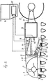
- Fig.2
- eine weitere Ausführungsform der Erfindung, und
- Fig.3
- eine schematische Darstellung einer Variante der Erfindung.
Claims (10)
- Automatische Höhensteuerung für Schlegler (1, 2, 3) mit Nachköpfer (11) von Maschinen zum Ernten von Wurzelfrüchten, bei der die Arbeitshöhe (7) der Schleglerwelle (2) auf das Niveau des Blattansatzes der Wurzelfrüchte (5, 6), und der Nachköpfer (11) auf das Niveau der abzunehmenden Kopfscheibe eingestellt wird, und die Einstellung unterschiedlichen Rübenbeständen angepaßt fortlaufend verändert wird, wobei eine dem Schlegler (1, 2, 3) zugeordnete Tastvorrichtung (12) die Schleglerwelle (2) bzw. das Schleglergehäuse (1) so beaufschlagt, daß die von der Tastvorrichtung (12) ausgeführte Höhenbewegung proportional auf die Schleglerwelle (2) bzw. das Schleglergehäuse (1) übertragen wird, dadurch gekennzeichnet, daß bei dem dem Schlegler (1, 2, 3) zugeordneten Nachköpfer (11) die Tastvorrichtung (12) auf die Kopfseite der Wurzelfrüchte (5, 6) mit Blättern zugestellt und abgetastet wird, daß die von der Tastvorrichtung (12) zurückgelegte Wegstrecke durch eine elektrische oder elektronische Vorrichtung (15) festgestellt wird, die die Höhenbewegung der Tastvorrichtung in elektrische Signale. umwandelt, und daß diese Signale in eine Antriebsbewegung mindestens eines Verstellzylinders (16) umgesetzt werden, die eine entsprechende Höhenbewegung des Schleglergehäuses (1) bzw. der Schleglerwelle (2) ausführt.
- Automatische Höhensteuerung nach Anspruch 1, dadurch gekennzeichnet, daß die dem Schlegler zugeordnete Tastvorrichtung (12) in Form einer Tasterzunge Teil des Nachköpfers (11) mit Köpfmesser (13) ist, das die Köpfdicke der Wurzelfrüchte festlegt, daß die Tasterzunge, die die Oberseite der Wurzelfrucht abtastet und auf eine bestimmte Köpfdicke eingestellt ist, über einen Träger mit dem Schleglergehäuse (1) fest verbunden ist, und daß bei einer Höhenverstellung der Tasterzunge aufgrund der Abtastung der Wurzelfrüchte diese Höhenbewegung in eine proportionale Höhenbewegung des Schleglergehäuses umgesetzt wird.
- Automatische Höhensteuerung nach Anspruch 2, dadurch gekennzeichnet, daß der mit der Tasterzunge verbundene Träger (1) als eine mit dem Schleglergehäuse bzw. der Schleglerwelle befestigte Parallelogrammführung ausgebildet ist, mit der ein Winkelaufnehmer (23) gekoppelt ist, der die Höhenbewegung der Tasterzunge (14) in ein elektrisches Signal umwandelt, das über einen Antriebszylinder die Parallelogrammführung analog der Höhenbewegung der Tasterzunge (14) steuert.
- Automatische Höhensteuerung nach Anspruch 2 oder 3, dadurch gekennzeichnet, daß der Winkelaufnehmer eine Potentiometeranordnung ist.
- Automatische Höhensteuerung nach einem der Ansprüche 1 - 4, dadurch gekennzeichnet, daß ein weiterer Winkelaufnehmer (32) dem Roder (29) zugeordnet ist, daß der Winkelaufnehmer (32) mit einer Parallelogrammführung (28) gekoppelt ist, daß die der Winkelbewegung des Winkelaufnehmers entsprechenden Signale der elektronischen Vorrichtung (25) zugeführt werden, und daß die Signale aus den beiden Winkelaufnehmern (23, 32) in der elektronischen Vorrichtung (25) verarbeitet werden und das Resultat der Verarbeitung dem Verstellzylinder (30) aufgegeben wird.
- Automatische Höhensteuerung nach einem der Ansprüche 1 - 5, dadurch gekennzeichnet, daß das Köpfmesser (13), mit der die Tasterzungen (12) aufnehmenden Parallelogrammführung (19) befestigt ist.
- Automatische Höhensteuerung nach einem der Ansprüche 1 - 6, dadurch gekennzeichnet, daß das Köpfmesser (13) mit den Tasterzungen (12) befestigt ist.
- Automatische Höhensteuerung nach einem der Ansprüche 1 - 7, dadurch gekennzeichnet, daß der Nachköpfer (11) über einen mit dem Schleglergehäuse (1) befestigten Hubzylinder (22) für die Grundeinstellung einstellbar ausgebildet ist.
- Automatische Höhensteuerung nach einem der Ansprüche 1 - 8, dadurch gekennzeichnet, daß die Wurzelfrucht-Erntemaschine eine mehrreihige Erntemaschine ist.
- Automatische Höhensteuerung nach Anspruch 9, dadurch gekennzeichnet, daß die Wurzelfrucht-Erntemaschine eine sechsreihige Rübenerntemaschine ist.
Applications Claiming Priority (3)
| Application Number | Priority Date | Filing Date | Title |
|---|---|---|---|
| DE19848484 | 1998-10-21 | ||
| DE19848484A DE19848484A1 (de) | 1998-10-21 | 1998-10-21 | Automatische Höhensteuerung für Schlegler mit Nachköpfer von Wurzelfruchterntemaschinen |
| PCT/DE1999/003367 WO2000022915A1 (de) | 1998-10-21 | 1999-10-20 | Automatische höhensteuerung für schlegler mit nachköpfer von wurzelfruchterntemaschinen |
Publications (3)
| Publication Number | Publication Date |
|---|---|
| EP1122995A1 EP1122995A1 (de) | 2001-08-16 |
| EP1122995B1 EP1122995B1 (de) | 2004-02-25 |
| EP1122995B9 true EP1122995B9 (de) | 2004-10-06 |
Family
ID=7885155
Family Applications (1)
| Application Number | Title | Priority Date | Filing Date |
|---|---|---|---|
| EP99957928A Expired - Lifetime EP1122995B9 (de) | 1998-10-21 | 1999-10-20 | Automatische höhensteuerung für schlegler mit nachköpfer von wurzelfruchterntemaschinen |
Country Status (6)
| Country | Link |
|---|---|
| EP (1) | EP1122995B9 (de) |
| AT (1) | ATE260019T1 (de) |
| AU (1) | AU1548500A (de) |
| DE (2) | DE19848484A1 (de) |
| DK (1) | DK1122995T3 (de) |
| WO (1) | WO2000022915A1 (de) |
Families Citing this family (5)
| Publication number | Priority date | Publication date | Assignee | Title |
|---|---|---|---|---|
| FR3018661B1 (fr) * | 2014-03-18 | 2016-05-06 | Exel Ind | Machine de recolte de racines comme des betteraves, comportant un moyen d’ajustement automatique de l’unite de recolte |
| CN108401639A (zh) * | 2018-03-14 | 2018-08-17 | 山东农业大学 | 一种高度自动调节萝卜切缨装置 |
| RU2740099C1 (ru) * | 2020-03-26 | 2021-01-11 | Федеральное государственное бюджетное научное учреждение Всероссийский научно-исследовательский институт сахарной свеклы и сахара имени А.Л. Мазлумова (ФГБНУ "ВНИИСС им. А.Л. Мазлумова") | Устройство для предварительной обрезки ботвы сахарной свеклы на корню |
| KR102514089B1 (ko) * | 2021-04-28 | 2023-03-24 | 농업회사법인 보경팜테크 주식회사 | 작물 절단 장치 |
| CN118176933B (zh) * | 2024-04-19 | 2026-03-31 | 山东五征高北农牧机械有限公司 | 一种苜蓿收获机倾角控制方法与装置 |
Family Cites Families (4)
| Publication number | Priority date | Publication date | Assignee | Title |
|---|---|---|---|---|
| DE3101770C2 (de) * | 1981-01-21 | 1985-10-24 | Friedrich 3216 Salzhemmendorf Brockmann | Vorrichtung zum Entblättern von in Reihen wachsenden Wurzelfrüchten vor dem Roden |
| BE901552A (fr) * | 1985-01-23 | 1985-05-17 | Agri Service S P R L | Dispositif tateur de tubercules en vue du decolletage et ou de l'effeuillage. |
| DE3502587A1 (de) * | 1985-01-26 | 1986-07-31 | Wilhelm Stoll Maschinenfabrik Gmbh, 3325 Lengede | Zweireihige rueben-koepfvorrichtung |
| DE3519889A1 (de) * | 1985-06-04 | 1986-12-04 | Heinrich 3013 Barsinghausen Bleinroth | Vorrichtung zum ernten von ruebenkoepfen |
-
1998
- 1998-10-21 DE DE19848484A patent/DE19848484A1/de not_active Withdrawn
-
1999
- 1999-10-20 DK DK99957928T patent/DK1122995T3/da active
- 1999-10-20 AT AT99957928T patent/ATE260019T1/de active
- 1999-10-20 AU AU15485/00A patent/AU1548500A/en not_active Abandoned
- 1999-10-20 EP EP99957928A patent/EP1122995B9/de not_active Expired - Lifetime
- 1999-10-20 WO PCT/DE1999/003367 patent/WO2000022915A1/de not_active Ceased
- 1999-10-20 DE DE59908664T patent/DE59908664D1/de not_active Expired - Lifetime
Also Published As
| Publication number | Publication date |
|---|---|
| DE59908664D1 (de) | 2004-04-01 |
| WO2000022915A1 (de) | 2000-04-27 |
| ATE260019T1 (de) | 2004-03-15 |
| DE19848484A1 (de) | 2000-04-27 |
| EP1122995B1 (de) | 2004-02-25 |
| DK1122995T3 (da) | 2004-06-21 |
| AU1548500A (en) | 2000-05-08 |
| EP1122995A1 (de) | 2001-08-16 |
Similar Documents
| Publication | Publication Date | Title |
|---|---|---|
| DE69109659T2 (de) | Messvorrichtung für erntegut. | |
| EP1880591B1 (de) | Kartoffelerntemaschine | |
| DE19853085B4 (de) | Verfahren zum Justieren einer an einer Feldmaschine befestigten Sensoreinheit sowie eine Justiereinrichtung und eine Feldmaschine | |
| EP3417686A1 (de) | Landwirtschaftliche arbeitsmaschine | |
| DE4441841A1 (de) | Tastvorrichtung zur selbsttätigen Seitenführung einer selbstfahrenden Erntemaschine | |
| EP1122995B9 (de) | Automatische höhensteuerung für schlegler mit nachköpfer von wurzelfruchterntemaschinen | |
| DE3235818A1 (de) | Einrichtung zur steuerung der arbeitstiefe eines bodenbearbeitungsgeraetes | |
| DE2947511C2 (de) | Absaugendes, ein Schlagmesserschneidwerk aufweisendes Mähwerk zum Anbringen an einem Tragfahrzeug | |
| EP0264011B1 (de) | Nachköpfeinrichtung für Rübenerntemaschinen | |
| DE102017008126A1 (de) | Landwirtschaftliche Arbeitsvorrichtung | |
| EP0818136A1 (de) | Einrichtung zum Häckseln von Pflanzen | |
| EP4480300A1 (de) | Halmteiler einer erntebergungsvorrichtung mit teilerspitze | |
| EP1306000A1 (de) | Verfahren zur Optimierung der Erzeugung von qualitativ hochwertigem Futter | |
| DD216371A5 (de) | Automatisch lenkbare hackfrucht-erntemaschine | |
| DE4240203C2 (de) | Ein- oder mehrreihige Rübenerntemaschine | |
| DE102019113601B4 (de) | Rübenvermessungsvorrichtung und Rübenrodeschartiefen-Steuerungsvorrichtung sowie Verfahren zum tiefengesteuerten Rübenroden | |
| DE4339254B4 (de) | Pflug mit zentraler Verstellung der Vorschäler | |
| EP0048907A1 (de) | Anbaugerätekombination für Traktoren | |
| DE2834463B2 (de) | Rübenköpfvorrichtung | |
| EP0303226A1 (de) | Mehrreihige Kartoffelerntemaschine | |
| EP3895514B1 (de) | Landwirtschaftliche bodenbearbeitungsvorrichtung und landwirtschaftliche maschinenkombination | |
| WO1988003358A1 (fr) | Arracheuse-chargeuse de betteraves | |
| DE3343663C2 (de) | Rübenköpfeinrichtung | |
| DE4035570A1 (de) | Mehrreihige rodeeinrichtung fuer wurzelfruechte | |
| DE3731246C2 (de) |
Legal Events
| Date | Code | Title | Description |
|---|---|---|---|
| PUAI | Public reference made under article 153(3) epc to a published international application that has entered the european phase |
Free format text: ORIGINAL CODE: 0009012 |
|
| 17P | Request for examination filed |
Effective date: 20010331 |
|
| AK | Designated contracting states |
Kind code of ref document: A1 Designated state(s): AT BE CH CY DE DK ES FI FR GB GR IE IT LI LU MC NL PT SE |
|
| AX | Request for extension of the european patent |
Free format text: AL;LT;LV;MK;RO;SI |
|
| 17Q | First examination report despatched |
Effective date: 20020911 |
|
| GRAP | Despatch of communication of intention to grant a patent |
Free format text: ORIGINAL CODE: EPIDOSNIGR1 |
|
| GRAS | Grant fee paid |
Free format text: ORIGINAL CODE: EPIDOSNIGR3 |
|
| GRAA | (expected) grant |
Free format text: ORIGINAL CODE: 0009210 |
|
| AK | Designated contracting states |
Kind code of ref document: B1 Designated state(s): AT BE DE DK FR GB IT NL SE |
|
| REG | Reference to a national code |
Ref country code: GB Ref legal event code: FG4D Free format text: NOT ENGLISH |
|
| REG | Reference to a national code |
Ref country code: IE Ref legal event code: FG4D Free format text: GERMAN |
|
| REF | Corresponds to: |
Ref document number: 59908664 Country of ref document: DE Date of ref document: 20040401 Kind code of ref document: P |
|
| PG25 | Lapsed in a contracting state [announced via postgrant information from national office to epo] |
Ref country code: SE Free format text: LAPSE BECAUSE OF FAILURE TO SUBMIT A TRANSLATION OF THE DESCRIPTION OR TO PAY THE FEE WITHIN THE PRESCRIBED TIME-LIMIT Effective date: 20040525 |
|
| GBT | Gb: translation of ep patent filed (gb section 77(6)(a)/1977) |
Effective date: 20040513 |
|
| REG | Reference to a national code |
Ref country code: DK Ref legal event code: T3 |
|
| LTIE | Lt: invalidation of european patent or patent extension |
Effective date: 20040225 |
|
| REG | Reference to a national code |
Ref country code: IE Ref legal event code: FD4D |
|
| PG25 | Lapsed in a contracting state [announced via postgrant information from national office to epo] |
Ref country code: GB Free format text: LAPSE BECAUSE OF NON-PAYMENT OF DUE FEES Effective date: 20041020 |
|
| ET | Fr: translation filed | ||
| PLBE | No opposition filed within time limit |
Free format text: ORIGINAL CODE: 0009261 |
|
| STAA | Information on the status of an ep patent application or granted ep patent |
Free format text: STATUS: NO OPPOSITION FILED WITHIN TIME LIMIT |
|
| 26N | No opposition filed |
Effective date: 20041126 |
|
| GBPC | Gb: european patent ceased through non-payment of renewal fee |
Effective date: 20041020 |
|
| REG | Reference to a national code |
Ref country code: FR Ref legal event code: PLFP Year of fee payment: 17 |
|
| PGFP | Annual fee paid to national office [announced via postgrant information from national office to epo] |
Ref country code: DK Payment date: 20151021 Year of fee payment: 17 |
|
| PGFP | Annual fee paid to national office [announced via postgrant information from national office to epo] |
Ref country code: IT Payment date: 20151028 Year of fee payment: 17 |
|
| PGFP | Annual fee paid to national office [announced via postgrant information from national office to epo] |
Ref country code: AT Payment date: 20151022 Year of fee payment: 17 Ref country code: BE Payment date: 20151019 Year of fee payment: 17 |
|
| REG | Reference to a national code |
Ref country code: FR Ref legal event code: PLFP Year of fee payment: 18 |
|
| PG25 | Lapsed in a contracting state [announced via postgrant information from national office to epo] |
Ref country code: BE Free format text: LAPSE BECAUSE OF NON-PAYMENT OF DUE FEES Effective date: 20161031 |
|
| REG | Reference to a national code |
Ref country code: DK Ref legal event code: EBP Effective date: 20161031 |
|
| REG | Reference to a national code |
Ref country code: AT Ref legal event code: MM01 Ref document number: 260019 Country of ref document: AT Kind code of ref document: T Effective date: 20161020 |
|
| PG25 | Lapsed in a contracting state [announced via postgrant information from national office to epo] |
Ref country code: AT Free format text: LAPSE BECAUSE OF NON-PAYMENT OF DUE FEES Effective date: 20161020 |
|
| REG | Reference to a national code |
Ref country code: FR Ref legal event code: PLFP Year of fee payment: 19 |
|
| PG25 | Lapsed in a contracting state [announced via postgrant information from national office to epo] |
Ref country code: IT Free format text: LAPSE BECAUSE OF NON-PAYMENT OF DUE FEES Effective date: 20161020 |
|
| PG25 | Lapsed in a contracting state [announced via postgrant information from national office to epo] |
Ref country code: DK Free format text: LAPSE BECAUSE OF NON-PAYMENT OF DUE FEES Effective date: 20161031 |
|
| REG | Reference to a national code |
Ref country code: BE Ref legal event code: MM Effective date: 20161031 |
|
| REG | Reference to a national code |
Ref country code: FR Ref legal event code: PLFP Year of fee payment: 20 |
|
| PGFP | Annual fee paid to national office [announced via postgrant information from national office to epo] |
Ref country code: NL Payment date: 20180913 Year of fee payment: 20 |
|
| PGFP | Annual fee paid to national office [announced via postgrant information from national office to epo] |
Ref country code: DE Payment date: 20181009 Year of fee payment: 20 |
|
| PGFP | Annual fee paid to national office [announced via postgrant information from national office to epo] |
Ref country code: FR Payment date: 20181030 Year of fee payment: 20 |
|
| REG | Reference to a national code |
Ref country code: DE Ref legal event code: R071 Ref document number: 59908664 Country of ref document: DE |
|
| REG | Reference to a national code |
Ref country code: NL Ref legal event code: MK Effective date: 20191019 |