EP1123180B1 - Vorrichtung zum herstellen und/oder verarbeiten von mehrkomponentengemischen - Google Patents
Vorrichtung zum herstellen und/oder verarbeiten von mehrkomponentengemischen Download PDFInfo
- Publication number
- EP1123180B1 EP1123180B1 EP99949009A EP99949009A EP1123180B1 EP 1123180 B1 EP1123180 B1 EP 1123180B1 EP 99949009 A EP99949009 A EP 99949009A EP 99949009 A EP99949009 A EP 99949009A EP 1123180 B1 EP1123180 B1 EP 1123180B1
- Authority
- EP
- European Patent Office
- Prior art keywords
- cam
- stirrer
- housing
- outlet
- shaft
- Prior art date
- Legal status (The legal status is an assumption and is not a legal conclusion. Google has not performed a legal analysis and makes no representation as to the accuracy of the status listed.)
- Expired - Lifetime
Links
- 239000000203 mixture Substances 0.000 title claims abstract description 43
- 239000000470 constituent Substances 0.000 title abstract 3
- 238000002156 mixing Methods 0.000 claims abstract description 54
- 230000006835 compression Effects 0.000 claims description 8
- 238000007906 compression Methods 0.000 claims description 8
- 238000000034 method Methods 0.000 claims description 5
- 230000002829 reductive effect Effects 0.000 claims description 4
- 230000009471 action Effects 0.000 claims description 2
- 230000003247 decreasing effect Effects 0.000 claims description 2
- 230000002093 peripheral effect Effects 0.000 claims 2
- 230000009977 dual effect Effects 0.000 claims 1
- 239000000463 material Substances 0.000 abstract description 12
- 230000009467 reduction Effects 0.000 abstract description 2
- 238000003756 stirring Methods 0.000 description 11
- 238000006073 displacement reaction Methods 0.000 description 5
- 238000004140 cleaning Methods 0.000 description 4
- 238000004519 manufacturing process Methods 0.000 description 3
- 230000001133 acceleration Effects 0.000 description 2
- 230000005540 biological transmission Effects 0.000 description 2
- 239000012530 fluid Substances 0.000 description 2
- 239000006260 foam Substances 0.000 description 2
- 238000001746 injection moulding Methods 0.000 description 2
- 238000007792 addition Methods 0.000 description 1
- 230000002411 adverse Effects 0.000 description 1
- 230000008859 change Effects 0.000 description 1
- 230000008878 coupling Effects 0.000 description 1
- 238000010168 coupling process Methods 0.000 description 1
- 238000005859 coupling reaction Methods 0.000 description 1
- 230000007423 decrease Effects 0.000 description 1
- 230000006866 deterioration Effects 0.000 description 1
- 230000007257 malfunction Effects 0.000 description 1
- 238000010943 off-gassing Methods 0.000 description 1
- 230000036316 preload Effects 0.000 description 1
- 230000008569 process Effects 0.000 description 1
- 230000000284 resting effect Effects 0.000 description 1
- 238000000518 rheometry Methods 0.000 description 1
- 238000005096 rolling process Methods 0.000 description 1
- 238000007789 sealing Methods 0.000 description 1
- 230000003068 static effect Effects 0.000 description 1
- 238000009423 ventilation Methods 0.000 description 1
Images


Classifications
-
- B—PERFORMING OPERATIONS; TRANSPORTING
- B29—WORKING OF PLASTICS; WORKING OF SUBSTANCES IN A PLASTIC STATE IN GENERAL
- B29B—PREPARATION OR PRETREATMENT OF THE MATERIAL TO BE SHAPED; MAKING GRANULES OR PREFORMS; RECOVERY OF PLASTICS OR OTHER CONSTITUENTS OF WASTE MATERIAL CONTAINING PLASTICS
- B29B7/00—Mixing; Kneading
- B29B7/30—Mixing; Kneading continuous, with mechanical mixing or kneading devices
- B29B7/34—Mixing; Kneading continuous, with mechanical mixing or kneading devices with movable mixing or kneading devices
- B29B7/38—Mixing; Kneading continuous, with mechanical mixing or kneading devices with movable mixing or kneading devices rotary
- B29B7/40—Mixing; Kneading continuous, with mechanical mixing or kneading devices with movable mixing or kneading devices rotary with single shaft
- B29B7/405—Mixing heads
- B29B7/407—Mixing heads with a casing closely surrounding the rotor, e.g. with conical rotor
-
- B—PERFORMING OPERATIONS; TRANSPORTING
- B29—WORKING OF PLASTICS; WORKING OF SUBSTANCES IN A PLASTIC STATE IN GENERAL
- B29B—PREPARATION OR PRETREATMENT OF THE MATERIAL TO BE SHAPED; MAKING GRANULES OR PREFORMS; RECOVERY OF PLASTICS OR OTHER CONSTITUENTS OF WASTE MATERIAL CONTAINING PLASTICS
- B29B7/00—Mixing; Kneading
- B29B7/30—Mixing; Kneading continuous, with mechanical mixing or kneading devices
- B29B7/34—Mixing; Kneading continuous, with mechanical mixing or kneading devices with movable mixing or kneading devices
- B29B7/38—Mixing; Kneading continuous, with mechanical mixing or kneading devices with movable mixing or kneading devices rotary
- B29B7/40—Mixing; Kneading continuous, with mechanical mixing or kneading devices with movable mixing or kneading devices rotary with single shaft
- B29B7/401—Mixing; Kneading continuous, with mechanical mixing or kneading devices with movable mixing or kneading devices rotary with single shaft having a casing closely surrounding the rotor, e.g. with a plunger for feeding the material
-
- B—PERFORMING OPERATIONS; TRANSPORTING
- B29—WORKING OF PLASTICS; WORKING OF SUBSTANCES IN A PLASTIC STATE IN GENERAL
- B29B—PREPARATION OR PRETREATMENT OF THE MATERIAL TO BE SHAPED; MAKING GRANULES OR PREFORMS; RECOVERY OF PLASTICS OR OTHER CONSTITUENTS OF WASTE MATERIAL CONTAINING PLASTICS
- B29B7/00—Mixing; Kneading
- B29B7/30—Mixing; Kneading continuous, with mechanical mixing or kneading devices
- B29B7/58—Component parts, details or accessories; Auxiliary operations
- B29B7/582—Component parts, details or accessories; Auxiliary operations for discharging, e.g. doors
-
- B—PERFORMING OPERATIONS; TRANSPORTING
- B29—WORKING OF PLASTICS; WORKING OF SUBSTANCES IN A PLASTIC STATE IN GENERAL
- B29B—PREPARATION OR PRETREATMENT OF THE MATERIAL TO BE SHAPED; MAKING GRANULES OR PREFORMS; RECOVERY OF PLASTICS OR OTHER CONSTITUENTS OF WASTE MATERIAL CONTAINING PLASTICS
- B29B7/00—Mixing; Kneading
- B29B7/74—Mixing; Kneading using other mixers or combinations of mixers, e.g. of dissimilar mixers ; Plant
- B29B7/76—Mixers with stream-impingement mixing head
- B29B7/7663—Mixers with stream-impingement mixing head the mixing head having an outlet tube with a reciprocating plunger, e.g. with the jets impinging in the tube
- B29B7/7684—Parts; Accessories
-
- B—PERFORMING OPERATIONS; TRANSPORTING
- B29—WORKING OF PLASTICS; WORKING OF SUBSTANCES IN A PLASTIC STATE IN GENERAL
- B29B—PREPARATION OR PRETREATMENT OF THE MATERIAL TO BE SHAPED; MAKING GRANULES OR PREFORMS; RECOVERY OF PLASTICS OR OTHER CONSTITUENTS OF WASTE MATERIAL CONTAINING PLASTICS
- B29B7/00—Mixing; Kneading
- B29B7/74—Mixing; Kneading using other mixers or combinations of mixers, e.g. of dissimilar mixers ; Plant
- B29B7/76—Mixers with stream-impingement mixing head
- B29B7/7631—Parts; Accessories
- B29B7/7652—Construction of the discharge orifice, opening or nozzle
- B29B7/7657—Adjustable discharge orifices, openings or nozzle openings, e.g. for controlling the rate of dispensing
Definitions
- the invention relates to a device for manufacturing and / or for processing multicomponent mixtures, in particular of Plastic mixtures, with a mixing head with at least one Inlet for the mixture or its components, with an im Mixing head rotating drivable stirrer for mixing the mixture or its components and with an outlet for the mixture, wherein the stirrer in the mixing head by means of a drive unit is arranged axially displaceable and according to his Axialposition the outlet releases or closes.
- the volume in the mixing area of the mixing head is increased so much within a very short time, that depending on the rheology of the mixture produced or its Do not component this fast enough from its inlet along the mixer side walls through the mixing area in Direction can flow to the spout, which increased abruptly To fill volumes in this area. It can then do so come that when the sudden lifting of the stirrer in the mixing head a vacuum is created, especially if the outlet is still with residues of the ejected in a previous processing Mixture is filled.
- US Pat. No. 4,883,645 shows a static mixing head without stirrer.
- This mixing head is equipped with a cleaning device with a provided with a thin cleaning flask which cleans the mixing chamber, when the supply is interrupted by the components.
- the cleaning piston can be turned off for cleaning and by one Axial drive, such as a cam drive, pushed back and forth become.
- the object of the invention is to provide a device of the aforementioned Art to improve so that a sudden opening or Closing the outlet opening avoided by the stirrer and thereby the adverse influences on sensitive, processed Materials are prevented.
- This task is with the invention achieved in that the drive unit has a mechanical Cam drive with at least one actuating cam having, with an attacking on the stirrer or its shaft Hubelement cooperates, wherein the at least one actuating cam a cam shape with steady or jerk-free course and one from the closed position to the outlet of the mixing head releasing position of the stirrer towards increasing cam radius Has.
- the cam gear with one or more Actuating cam with variable cam radius for opening the outlet raises the lifting element and thus the stirrer or raise, it is possible to increase the speed of the stirrer when opening from a very low value at the beginning of the lifting movement in the further course of the axial displacement of the stirrer get faster.
- the cam drive allows the Use of actuating cams with various cam surfaces, the optimal to the material and flow behavior of the straight can be adapted to processing material.
- actuating cam a cam shape with steady or have / have smooth progress, they provide for a lifting or Retracting the stirrer in the mixing head with evenly growing Speed without acceleration jumps, that is without sudden movements of the stirrer during the entire opening process, so that the volume in the mixing chamber is continuous enlarged and of the processed material without time delay can be completed. From the closed position to the outlet of the mixing head releasing position of the stirrer out Increasing cam radius makes it possible, while maintaining the same Drive speed of the drive element, the opening speed of the stirrer when opening the outlet continuously to enlarge or at the closing of a high speed at a very low speed just before reaching to reduce the closed position.
- the mixture in the mixing head can already to this, during the opening movement the most critical When the volume in the mixing head is increasing, so that the stirrer by its displacement in the mixing chamber the mixing head generates no negative pressure and the mixed, too Do not outgas processing multicomponent mixture and thereby can experience a loss of quality.
- the cam drive expediently has at least one actuating cam having camshaft in a bearing housing is rotatably mounted laterally next to the agitator shaft.
- a cam drive with two arranged in parallel Camshafts to provide each with an actuating cam, the in a common bearing housing on both sides of the agitator shaft are rotatably mounted.
- the Hubelement preferably on the agitator shaft, so that the entire Drive unit for the displacement of the stirrer in his Axial direction away from the actual mixing head can be. There is therefore no danger that the drive unit with their partly highly accurate manufactured parts in Contact comes with the multi-component mixture to be processed, resulting in errors or inaccuracies when opening and closing could lead to the outlet.
- a particularly advantageous drive for the camshaft results themselves, if they are each provided with a drive gear are that of an axially displaceable driven Rack drive element are rotatable.
- the rack drive element can do this with a double or circumferential Gearing for both drive gears in the two preferably be provided parallel camshafts.
- the drive element essentially from the piston of a hydraulic or pneumatic piston-cylinder unit consists or coupled with this.
- the of the compressed air or the Hydraulic fluid on the piston of the piston-cylinder unit applied pressure is transmitted through the rack or other suitable Transmission element transferred to the cam drive and of this in the non-uniform, the stirrer with ever-increasing Speed from the outlet lifting opening movement implemented.
- the drive element preferably has an axial guide bore on, at least partially receives the helical compression spring.
- the designed as a helical spring return spring can also in addition to or as an alternative to the guide bore around one Guide pin to be wound, which also ensures that the Spring compressed or pulled apart only in their axial direction can be and a lateral deflection of the spring not taking place.
- the actuating cams of the two parallel camshafts preferably mirror images configured to each other and the associated camshafts are driven in opposite directions.
- the actuating cams can be interchangeable arranged on the associated camshaft, which makes it possible, by simply exchanging only the Actuating cams the opening movement and speed of the Stirrer optimally adapted to various mixtures to be processed.
- the lifting element is preferably in the axial direction of the agitator shaft adjustable connected to this.
- the adjustable connection makes it possible to adjust the device so that the or the actuating cam in the closed position of the stirrer with are very little play without direct contact to the lifting element, so that it is ensured that the stirrer with its tip the Outlet completely closes.
- the lifting element can essentially from an operating sleeve surrounding the stirrer shaft coaxially and one with this adjustable screwed bearing mount exist for a thrust bearing of the agitator shaft. The adjustability of the lifting element on the agitator shaft is then by Einoder Unscrew the bearing receiver from or into the actuating sleeve allows.
- the thrust bearing which is on the lifting element Axial movement exerted by the cams on the stirrer shaft transmits and thereby shifts in the housing, it is preferable from a radial deep groove ball bearing, which thus simultaneously the arranged at one end of the agitator shaft radial shaft bearing forms.
- the radial deep groove ball bearing allows so not just the rotation of the shaft about its own axis, but also allows the transmission of axial forces when rotating Shaft for their displacement in the housing.
- the lifting element is expedient of the or the actuating cam against the action of a closing spring in the housing axially displaceable.
- the closing spring ensures a return of the Lifting element and thus at the same time the stirrer for closing the outlet when the actuating cam in its original Be turned back position before opening the outlet had at the mixing head.
- the closing spring pushes over the lifting element the stirrer shaft and thus the stirrer with its tip firmly against the outlet and closes it against the unwanted Outlet of material still in the mixing chamber reliable.
- the stirrer shaft sleeve-like surrounds and is provided with an external thread, with the in a provided on the actuating sleeve internal thread is screwed.
- the bearing mount of the Housing outside opposite the actuating sleeve adjustable, for what they received axially displaceable in a guide sleeve may be, which is rotatably arranged in the housing while the Bearing support relative to the guide sleeve in the circumferential direction is locked.
- this has at least one stop element for the stirrer or the agitator shaft on.
- the stop element limits the opening travel, the shaft or the stirrer to fully open the Outlet has to cover.
- the stop element may be in a housing head be arranged, with which the housing terminates at the end. The arrangement is preferably made such that the housing head is a cylindrical receptacle for the upper or forms the rear end of the agitator shaft, wherein the receptacle is an internal thread has, in which the stop element screwed adjustably is.
- the adjustable arrangement of the stop element in Housing head allows a change and adjustment of the stroke of the stirrer so that the size of the stirrer tip and the outlet defined annular gap is variable and on Materials with different properties are adapted can.
- the agitator shaft does not strike the stop element itself but the attack takes place indirectly via the camp admission.
- the closing spring can also be in the housing head be arranged, with their first end in the axial direction acting on the agitator shaft or its bearing receptacle and arranged with its second end to a housing head Spring stop supported. It is particularly useful when the spring stop is adjustably arranged in the housing head is, for example, as well as the stop element in the housing head provided internal thread is screwed.
- the first End of the closing spring can be connected to the bearing support Applying spring plate act on the stirrer shaft, the Spring force evenly over the entire circumference of the bearing support distributed and so as pure, centric axial force in the Stirrer initiates.
- Such a procedure that is especially advantageous with the cam drive of the device according to the invention can be carried out, but of course by another suitable drive means on the device such as a controlled hydraulic drive can be realized allows a very gentle treatment even more sensitive Materials in the processing in the mixing head, so that qualitatively high-quality components can be produced by the method.
- 10 denotes a device according to the invention for mixing and processing the components of a plastic mixture,
- a sealing foam for example, a sealing foam
- the on Component is molded to form a seal.
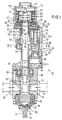
- the device 10 consists essentially of a in Figs. 1 and 2 shown below mixing head 11 with an above it flanged bearing housing 12, in turn, at its upper End is completed with a housing head 13.
- a mixing chamber 14 is formed in a manner known per se, into which a plurality of inlets 15 open radially, through which the components of the component to be mixed and not shown be supplied to be sprayed plastic mixture.
- the lower part of the mixing chamber 14 is from the stirrer head 16th a stirrer 17 to form a gap 18 to the wall 19th the mixing chamber filled, with the help of the supplied plastic components can be mixed together.
- the tip 20 immediately before the opening 21 of a mixture outlet, the cannula-like similar to a syringe in the lower or front Tip 23 of the mixing head 11 is arranged.
- the stirrer 17 is connected to a stirrer shaft 24, which is rotatably mounted in the bearing housing 12.
- a stirrer shaft 24 which is rotatably mounted in the bearing housing 12.
- the Drive provides an unillustrated drive motor, to the Housing head 13 is flanged and the output shaft through a disposed in the housing head cover 25 opening in the Housing head protrudes and there via a suitable coupling the upper end of the agitator shaft is connected.
- the stirrer is not only used with its stirring head 16, the individual Components of the plastic mixture to be processed but also has the task of the opening 21 of the outlet 22 with its front tip 20 to close in the manner of a nozzle needle or Ejifug of the mixture.
- the stirrer 17 together with his Stirrer shaft axially displaceable in the mixing chamber 14 and stored the bearing housing 12.
- the arrangement is made in this way, that the agitator shaft 24 relative to the inner ring 26 of the lower main roller bearing 27 of the shaft can move with its outer ring 28 fixed between two housing parts 12a, 12b the bearing housing 12 is installed.
- the agitator shaft 24 with a second bearing 29th stored At her in the drawing upper end is the agitator shaft 24 with a second bearing 29th stored, the inner ring 30 on a shaft paragraph by means of a countered shaft nut 31 is fixed while the outer ring of designed as deep groove ball bearing roller bearing 29th is arranged in a bearing receptacle 32.
- the bearing again is mounted axially displaceable in a guide sleeve 33, being to prevent rotation relative to the guide sleeve has a groove 35 extending in the axial direction 34, in the one arranged on the guide sleeve, radially inwardly projecting Retaining pin 36 engages.
- the guide sleeve 33 with one of the Housing outside 37 accessible tool connection 38 provided so that they use a suitable tool from the outside in the housing can be twisted.
- the cam drive 40 has two parallel camshafts 41 with one each, formed at one end of the camshaft actuating cam 42a, b, in the bearing housing 12 on both sides of the agitator shaft are rotatably mounted transversely to this.
- the camshafts 41 provided with drive gears 43a, b, about them from a common rack drive element 44 with double teeth 45 are rotatable in opposite directions.
- the rack drive member 44 is driven by a piston rod 46 of a piston 47 formed, the part of a pneumatic Piston-cylinder unit 48, which is also in the Housing 12 is located laterally next to the agitator shaft.
- the piston rod 46 is as Hollow cylinder formed with an axial guide bore 51st for a helical compression spring 52, on the one hand at the bottom of the hole 53 of the guide bore 51 arranged on a there Spring pad 54 and on the other hand on the upper end face 55th a cylinder chamber 56 is supported, in which the piston rod 46th is received axially displaceable.
- the helical compression spring 52 serves as a return spring for the piston 47 in the dashed, lowest position, if the cylinder chamber 49 is not acted upon by compressed air.
- actuating cams 42a, b are configured in mirror image to each other and have a cam radius r , which steadily increases over a rotation angle of about 180 ° from a minimum value to a maximum value.
- the cams 42 act on the lower end of an actuating sleeve 59 which surrounds the agitator shaft 24 and forms a lifting element 60 for displacing the agitator shaft 24 together with the mixing head 16 arranged thereon, together with the bearing receptacle 32 screwed in at the upper end of the actuating sleeve.
- the closing spring 64 presses over the spring plate 61, the bearing seat 32 and the upper deep groove ball bearing 29 the agitator shaft 24 and thus also the stirring head 16 firmly after down towards the mixing chamber 14, in which the stirrer tip 20 then tightly against the edge of the opening 21 applies.
- Fig. 4 one recognizes that in the lowest Position of the lifting element 16, ie in the opening 21st closing position of the stirring head 16, between the actuating cam 42a, b and the actuating sleeve 59 a small gap remains.
- This gap serves to ensure that the Stirring head with its tip 20 over the stirrer shaft and the rest involved components of the device of the closing spring 64th actually pressed into tight contact with the edge of the opening 21 is, so sure completely closed and not about an annular gap between the tip 20 and the edge of the opening 21st remains, without the recognizable in Fig. 4 gap 66 between Actuating cam and actuating sleeve could occur.
- the special serves already indicated above Embodiment of the guide sleeve 33, the axially displaceable therein, relative to the guide sleeve, however, non-rotatable bearing support 33 and the actuating sleeve 59, in its passage bore 67 provided for the agitator shaft 24 with a thread 68 is, in which the bearing holder 32 with a threaded extension 69 is screwed.
- the actuating sleeve 59 is in the housing 12th Although recorded axially displaceable, but may be opposite Do not twist the housing, resulting in a non-circular cross-section the actuating sleeve 59 is made possible by a Comparison of the wall thicknesses of the sleeve 59 in Figs. 1 and 2 can be seen is.
- the guide sleeve 33 from one of the housing outside 37 forth on the tool connection 38 connected tool in the housing twisted be, with the retaining pin 36 entrains the bearing seat 32 and depending on the direction of rotation, the threaded extension 69 in the actuating sleeve on or unscrews and so the axial position of the Actuating sleeve changed in the housing.
- the relative position of Lifting element 60 and actuating cam of the cam drive 40 can to be easily and accurately adjusted so that the game 66 between cam and actuating sleeve in the in Fig. 4th shown closure position as low as possible, but in each Case is sufficiently large to secure closure in the mixing head to ensure.
- the invention is not limited to the illustrated and described Embodiment limited, but there are many Changes and additions, without the scope of the invention leave.
- the actuating cam replaceable to attach to the camshaft and not the complete camshafts, but only the cams themselves exchange.
- pneumatic cylinder can of course also a hydraulic cylinder or another suitable drive for the cam gear selected be, for example, an electric motor, which has a suitable Reduction gear, the two camshafts rotates.
- radial ball bearings for the stirrer shaft can also be used for high stirrer speeds particularly suitable needle roller bearing or the like. use find, in which case the axial movement of the lifting element via a separate axial roller bearing is transmitted to the agitator shaft, since Needle roller bearings other than deep groove ball bearings do not allow axial forces transfer assets.
Landscapes
- Engineering & Computer Science (AREA)
- Mechanical Engineering (AREA)
- Processing And Handling Of Plastics And Other Materials For Molding In General (AREA)
- Agricultural Chemicals And Associated Chemicals (AREA)
Description
- Fig. 1
- eine Vorrichtung zum Verarbeiten von Kunststoffgemischen nach der Erfindung in einem Vertikalschnitt;
- Fig. 2
- den Gegenstand der Fig. 1 in einem Schnitt längs der Linie II-II;
- Fig. 3
- den Gegenstand der Fig. 1 in einem Querschnitt längs der Linie III-III; und
- Fig. 4
- einen Teil einer Antriebseinheit der erfindungsgemäßen Vorrichtung in deren Schließstellung in einer vergrößerten Schnittdarstellung entsprechend der Darstellung nach Fig. 2.
Claims (33)
- Vorrichtung zum Herstellen und/oder Verarbeiten von Mehrkomponentengemischen, insbesondere von Kunststoffgemischen mit einem Mischkopf mit mindestens einem Einlaß für das Gemisch oder dessen Komponenten, mit einem im Mischkopf drehend antreibbaren Rührer zum.Vermischen des Gemisches bzw. dessen Komponenten und mit einem Auslaß für das Gemisch, wobei der Rührer im Mischkopf mittels einer Antriebseinheit axial verschieblich angeordnet ist und entsprechend seiner Axialposition den Auslaß freigibt oder verschließt, dadurch gekennzeichnet, daß die Antriebseinheit (39) einen mechanischen Nockentrieb (40) mit mindestens einer Betätigungsnocke (42) aufweist, die mit einem am Rührer (17) bzw. dessen Welle (24) angreifenden Hubelement (60) zusammenwirkt, wobei die mindestens eine Betätigungsnocke (42) eine Nockenform mit stetigem bzw. ruckfreiem Verlauf und einen von der Schließstellung zur den Auslaß (22) des Mischkopfes (11) freigebenden Stellung des Rührers (17) hin größer werdenden Nockenradius (r) hat.
- Vorrichtung nach Anspruch 1, dadurch gekennzeichnet, daß der Nockentrieb (40) mindestens eine eine Betätigungsnocke (42) aufweisende Nockenwelle (41) hat, die in einem Lagergehäuse (12) seitlich neben der Rührerwelle (24) drehbar gelagert ist.
- Vorrichtung nach Anspruch 1 oder 2, dadurch gekennzeichnet, daß der Nockentrieb (40) zwei parallel angeordnete Nockenwellen (41) mit je einer Betätigungsnocke (42a,b) aufweist, die in einem gemeinsamen Lagergehäuse (12) beidseitig der Rührerwelle (24) drehbar gelagert sind.
- Vorrichtung nach einem der Ansprüche 1 bis 3, dadurch gekennzeichnet, daß die Nockenwellen (41) im Gehäuse (12) gegenläufig drehend angetrieben sind.
- Vorrichtung nach Anspruch 3 oder 4, dadurch gekennzeichnet, daß die Nockenwellen (41) ein gemeinsames Antriebselement (44) aufweisen.
- Vorrichtung nach einem der Ansprüche 1 bis 5, dadurch gekennzeichnet, daß die Nockenwelle(n) (41) mit je einem Antriebszahnrad (43a,b) versehen ist/sind, das/die von einem in Axialrichtung (34) verschieblich angetriebenen Zahnstangen-Antriebselement (44) drehbar ist/sind.
- Vorrichtung nach Anspruch 6, dadurch gekennzeichnet, daß das Zahnstangen-Antriebselement (44) mit einer Doppel- oder umlaufenden Verzahnung (45) für beide Antriebszahnräder (43a,b) bei zwei parallel angeordneten Nockenwellen (41) versehen ist.
- Vorrichtung nach einem der Ansprüche 1 bis 7, dadurch gekennzeichnet, daß das Antriebselement (44) im wesentlichen aus dem Kolben (47) einer hydraulischen oder pneumatischen Kolben-Zylindereinheit (48) besteht oder mit diesem gekoppelt ist.
- Vorrichtung nach einem der Ansprüche 1 bis 8, dadurch gekennzeichnet, daß dem Antriebselement (44) eine Rückstellfeder (52) zugeordnet ist.
- Vorrichtung nach Anspruch 9, dadurch gekennzeichnet, daß das Antriebselement (44) eine axiale Führungsbohrung (51) für die als Schraubendruckfeder ausgebildete Rückstellfeder (52) aufweist.
- Vorrichtung nach Anspruch 9 oder 10, gekennzeichnet durch einen Führungsdorn (57) für die als Schraubenfeder ausgestaltete Rückstellfeder (52).
- Vorrichtung nach einem der Ansprüche 1 bis 11, dadurch gekennzeichnet, daß die Betätigungsnocken (42a,b) der beiden parallel angeordneten Nockenwellen (41) spiegelbildlich zueinander ausgestaltet und die zugehörigen Nockenwellen (41) gegenläufig angetrieben sind.
- Vorrichtung nach einem der Ansprüche 1 bis 12, dadurch gekennzeichnet, daß die Nocke(n) (42a,b) auswechselbar an der zugehörigen Nockenwelle (41) angeordnet ist/sind.
- Vorrichtung nach einem der Ansprüche 1 bis 13, dadurch gekennzeichnet, daß die Nockenwelle(n) (41) auswechselbar im Gehäuse (12) gelagert ist/sind.
- Vorrichtung nach einem der Ansprüche 1 bis 14, dadurch gekennzeichnet, daß das Hubelement (60) in Axialrichtung (34) der Rührerwelle (24) verstellbar an dieser angeschlossen ist.
- Vorrichtung nach einem der Ansprüche 1 bis 15, dadurch gekennzeichnet, daß das Hubelement (60) im wesentlichen aus einer die Rührerwelle (24) koaxial umgebenden Betätigungshülse (59) und einer mit dieser einstellbar verschraubten Lageraufnahme (32) für ein Axiallager (29) der Rührerwelle (24) besteht.
- Vorrichtung nach Anspruch 16, dadurch gekennzeichnet, daß das Axiallager ( 29) aus einem Radial-Rillenkugellager besteht.
- Vorrichtung nach einem der Ansprüche 1 bis 17, dadurch gekennzeichnet, daß das Hubelement (60) von der/den Betätigungsnocke(n) (42a,b) entgegen der Wirkung einer Schließfeder (64) im Gehäuse (12) axial verschieblich ist.
- Vorrichtung nach einem der Ansprüche 1 bis 18, dadurch gekennzeichnet, daß die Lageraufnahme (32) die Rührerwelle (24) hülsenartig umgibt und mit einem Außengewinde (69) versehen ist, mit dem sie in ein an der Betätigungshülse (59) vorgesehenes Innengewinde (68) eingeschraubt ist.
- Vorrichtung nach einem der Ansprüche 1 bis 19, dadurch gekennzeichnet, daß die Lageraufnahme (32) von der Gehäuseaußenseite (37) gegenüber der Betätigungshülse (59) einstellbar ist.
- Vorrichtung nach einem der Ansprüche 1 bis 20, dadurch gekennzeichnet, daß die Lageraufnahme (32) in einer Führungshülse (33) axial verschieblich aufgenommen ist.
- Vorrichtung nach einem der Ansprüche 1 bis 21, dadurch gekennzeichnet, daß die Lageraufnahme (32) gegenüber der Führungshülse (33) in Umfangsrichtung arretiert ist.
- Vorrichtung nach Anspruch 21 oder 22, dadurch gekennzeichnet, daß die Führungshülse (33) im Gehäuse (12) verdrehbar aufgenommen ist.
- Vorrichtung nach einem der Ansprüche 21 bis 23, dadurch gekennzeichnet, daß die Führungshülse (33) mit mindestens einem radial nach innen vorspringenden Haltestift (36) versehen ist, der in eine an der Lageraufnahme (32) in Axialrichtung (34) verlaufende Nut (35) einfaßt.
- Vorrichtung nach einem der Ansprüche 21 bis 24, dadurch gekennzeichnet, daß die Führungshülse (33) mit einem von der Gehäuseaußenseite (37) zugänglichen Werkzeuganschluß (38) versehen ist.
- Vorrichtung nach einem der Ansprüche 1 bis 25, gekennzeichnet durch mindestens ein Anschlagelement (62) für den Rührer (17) bzw. die Rührerwelle (24).
- Vorrichtung nach einem der Ansprüche 1 bis 26, dadurch gekennzeichnet, daß das Gehäuse (12) einen Gehäusekopf (13) aufweist, in dem das Anschlagelement (62) angeordnet ist.
- Vorrichtung nach einem der Ansprüche 1 bis 27, dadurch gekennzeichnet, daß der Gehäusekopf (13) eine zylindrische Aufnahme für das obere bzw. hintere Ende der Rührerwelle (24) bildet und ein Innengewinde (63) aufweist, in das das Anschlagelement (62) verstellbar eingeschraubt ist.
- Vorrichtung nach einem der Ansprüche 1 bis 28, dadurch gekennzeichnet, daß die Rührerwelle (24) am Anschlagelement (62) mittelbar über die Lageraufnahme (32) anschlägt.
- Vorrichtung nach einem der Ansprüche 1 bis 29, dadurch gekennzeichnet, daß die Schließfeder (64) im Gehäusekopf (13) angeordnet ist und mit ihrem ersten Ende in Axialrichtung auf die Rührerwelle (24) bzw. deren Lageraufnahme (32) einwirkt und sich mit ihrem zweiten Ende an einem Federanschlag (65) abstützt.
- Vorrichtung nach einem der Ansprüche 1 bis 30, dadurch gekennzeichnet, daß das erste Ende der Schließfeder (64) über einen sich an die Lageraufnahme (32) anlegenden Federteller (61) auf die Rührerwelle (24) einwirkt.
- Vorrichtung nach einem der Ansprüche 1 bis 31, dadurch gekennzeichnet, daß der Federanschlag ( 65) verstellbar im Gehäusekopf (13) angeordnet ist.
- Verfahren zum Öffnen und Schließen eines Verschlußelements in einer Vorrichtung zum Herstellen und/oder Verarbeiten von Mehrkomponentengemischen nach dem Oberbegriff des Anspruches 1, bei dem das Verschlußelement bzw. der dieses bildende Rührer (17) beim Öffnen zum Freigeben eines Auslasses (22) erst langsam von der Auslaßöffnung (21) abgehoben und mit zunehmendem Abstand von der Auslaßöffnung (21) zunehmend schneller von dieser weg bewegt wird und bei dem beim Schließen zum Absperren des Auslasses (22) das im Abstand von der Auslaßöffnung befindliche Verschlußelement (17) erst mit höherer Geschwindigkeit auf die Öffnung zu bewegt wird und mit abnehmendem Abstand von der Öffnung (21) bei Annäherung an diese die Schließgeschwindigkeit verringert wird.
Applications Claiming Priority (3)
| Application Number | Priority Date | Filing Date | Title |
|---|---|---|---|
| DE19848357A DE19848357A1 (de) | 1998-10-21 | 1998-10-21 | Vorrichtung zum Herstellen und/oder Verarbeiten von Mehrkomponentengemischen |
| DE19848357 | 1998-10-21 | ||
| PCT/EP1999/007937 WO2000023235A1 (de) | 1998-10-21 | 1999-10-19 | Vorrichtung zum herstellen und/oder verarbeiten von mehrkomponentengemischen |
Publications (2)
| Publication Number | Publication Date |
|---|---|
| EP1123180A1 EP1123180A1 (de) | 2001-08-16 |
| EP1123180B1 true EP1123180B1 (de) | 2003-12-10 |
Family
ID=7885075
Family Applications (1)
| Application Number | Title | Priority Date | Filing Date |
|---|---|---|---|
| EP99949009A Expired - Lifetime EP1123180B1 (de) | 1998-10-21 | 1999-10-19 | Vorrichtung zum herstellen und/oder verarbeiten von mehrkomponentengemischen |
Country Status (8)
| Country | Link |
|---|---|
| US (1) | US6592249B1 (de) |
| EP (1) | EP1123180B1 (de) |
| JP (1) | JP4794044B2 (de) |
| AT (1) | ATE255992T1 (de) |
| CA (1) | CA2347624C (de) |
| DE (2) | DE19848357A1 (de) |
| ES (1) | ES2209512T3 (de) |
| WO (1) | WO2000023235A1 (de) |
Families Citing this family (12)
| Publication number | Priority date | Publication date | Assignee | Title |
|---|---|---|---|---|
| US10052666B1 (en) * | 2014-11-07 | 2018-08-21 | Easy Foam, Inc. | In situ foam generation apparatus for on-site, on-demand, economical production of foaming solvents |
| CN104400928B (zh) * | 2014-11-11 | 2017-01-18 | 浙江师范大学 | 一种可用于原位成型的微量聚合物复合材料循环混炼装置 |
| AT517337B1 (de) * | 2015-07-03 | 2017-01-15 | Sonderhoff Engineering Gmbh | Mischvorrichtung |
| AT516947B1 (de) * | 2015-07-03 | 2016-10-15 | Sonderhoff Eng Gmbh | Mischvorrichtung |
| DE102018008035A1 (de) * | 2017-10-20 | 2019-04-25 | Hilger U. Kern Gmbh | Vorrichtung zum Mischen von zwei oder mehr Komponenten sowie Verfahren zur Kalibrierung einer solchen |
| DE102019114743A1 (de) * | 2019-06-03 | 2020-12-03 | Hilger U. Kern Gmbh | Vorrichtung zum mischen von zwei oder mehr komponenten sowie verfahren zur kalibrierung einer solchen |
| DE102019208473A1 (de) | 2019-06-11 | 2020-12-17 | Henkel Ag & Co. Kgaa | Vorrichtung zum Herstellen eines Mehrkomponentengemisches und Verfahren zum Betreiben einer derartigen Vorrichtung |
| DE102019208475A1 (de) * | 2019-06-11 | 2020-12-17 | Henkel Ag & Co. Kgaa | Vorrichtung zum Herstellen und Verarbeiten eines Mehrkomponentengemisches und Verfahren zum Betreiben einer derartigen Vorrichtung |
| CN112520833B (zh) * | 2020-11-30 | 2021-08-31 | 鹤壁市质量技术监督检验测试中心 | 一种实验室污水中和装置 |
| IT202100012113A1 (it) * | 2021-05-11 | 2022-11-11 | Afros Spa | Dispositivo-iniettore per un'apparecchiatura idonea alla miscelazione di componenti chimicamente reattivi |
| CN113813825A (zh) * | 2021-10-15 | 2021-12-21 | 无锡全世全流体科技有限公司 | 一种搅拌叶片角度可调节的搅拌器 |
| CN120900890A (zh) * | 2025-08-18 | 2025-11-07 | 上海凯伟智能科技(集团)有限公司 | 一种多组份涂胶喷头的恒压阀机构 |
Family Cites Families (20)
| Publication number | Priority date | Publication date | Assignee | Title |
|---|---|---|---|---|
| US3164375A (en) * | 1955-10-14 | 1965-01-05 | Frenkel Ag C D | Apparatus for intensive mixing |
| AT316850B (de) | 1969-12-17 | 1974-07-25 | Semperit Ag | Vorrichtung zum chargenweisen Mischen und Fördern |
| CH555738A (de) * | 1973-03-09 | 1974-11-15 | Netstal Ag Maschf Giesserei | Kunstsoff-spritzgiessmaschine. |
| DE2419961A1 (de) | 1974-04-25 | 1975-11-06 | Wikolin Polymer Chemie | Verfahren und giesskopf zum taktweisen einspritzen bzw. giessen von fliessfaehigen kunststoffen, insbesondere polyurethan |
| DE3013237A1 (de) * | 1980-04-03 | 1981-10-08 | Bayer Ag, 5090 Leverkusen | Verfahren und vorrichtung zum herstellen eines aus mindestens zwei fliessfaehigen reaktionskomponenten und fuellstoffen bestehenden, massiv- oder schaumstoff bildenen gemisches |
| JPS62114265A (ja) | 1985-11-13 | 1987-05-26 | Mitsubishi Electric Corp | 半導体記憶装置 |
| DE3621463A1 (de) * | 1986-06-26 | 1988-01-21 | Krauss Maffei Ag | Antriebseinrichtung fuer eine schneckenspritzgiessmaschine sowie verfahren zum steuern einer derartigen antriebseinrichtung |
| DE3629042C1 (de) * | 1986-08-27 | 1988-04-07 | Kloeckner Ferromatik Desma | Mischkopf zum Herstellen eines chemisch reagierenden Gemisches |
| CH670580A5 (de) * | 1987-04-16 | 1989-06-30 | Ehrensperger C Ag | |
| JPS6480408A (en) * | 1987-09-24 | 1989-03-27 | Tosoh Corp | Separation of metal ion by electrodialysis |
| JPH077134Y2 (ja) * | 1989-12-14 | 1995-02-22 | ティーディーケイ株式会社 | 射出成形機の射出装置 |
| JP3067789B2 (ja) | 1990-09-14 | 2000-07-24 | ティーディーケイ株式会社 | 射出成形装置 |
| US5123833A (en) * | 1991-04-01 | 1992-06-23 | Parker John C | Fast cycle plasticator/injector unit for molding machines |
| JPH05124071A (ja) | 1991-11-05 | 1993-05-21 | Masao Kubota | 射出成形機の駆動機構 |
| DE4214780A1 (de) * | 1992-05-04 | 1993-11-11 | Flaekt Ransburg Bmbh | Mischen von flüssigen Medien |
| DE4235850B4 (de) * | 1992-10-23 | 2008-11-06 | Edf Polymer-Applikation Maschinenfabrik Gmbh | Mischkopf zur Verarbeitung von Mehrkomponenten-Kunststoffgemischen |
| US5450368A (en) * | 1993-12-28 | 1995-09-12 | Three Bond Co., Ltd. | Two liquid type mixer |
| EP0723843A3 (de) * | 1995-01-27 | 1997-03-26 | Nordson Corp | Abgabekopf für Zweikomponentenschaum mit Abstellvorrichtung |
| JPH1029213A (ja) * | 1996-07-15 | 1998-02-03 | Toray Dow Corning Silicone Co Ltd | 液状材料連続混合装置 |
| DE19819759C2 (de) * | 1998-05-04 | 2001-09-27 | Battenfeld Gmbh | Vorrichtung zur Betätigung eines Einspritzelements |
-
1998
- 1998-10-21 DE DE19848357A patent/DE19848357A1/de not_active Withdrawn
-
1999
- 1999-10-19 DE DE59908035T patent/DE59908035D1/de not_active Expired - Lifetime
- 1999-10-19 EP EP99949009A patent/EP1123180B1/de not_active Expired - Lifetime
- 1999-10-19 US US09/806,114 patent/US6592249B1/en not_active Expired - Lifetime
- 1999-10-19 CA CA002347624A patent/CA2347624C/en not_active Expired - Lifetime
- 1999-10-19 JP JP2000576998A patent/JP4794044B2/ja not_active Expired - Lifetime
- 1999-10-19 WO PCT/EP1999/007937 patent/WO2000023235A1/de not_active Ceased
- 1999-10-19 AT AT99949009T patent/ATE255992T1/de active
- 1999-10-19 ES ES99949009T patent/ES2209512T3/es not_active Expired - Lifetime
Also Published As
| Publication number | Publication date |
|---|---|
| JP2002527261A (ja) | 2002-08-27 |
| DE59908035D1 (de) | 2004-01-22 |
| ATE255992T1 (de) | 2003-12-15 |
| CA2347624C (en) | 2008-02-19 |
| CA2347624A1 (en) | 2000-04-27 |
| US6592249B1 (en) | 2003-07-15 |
| EP1123180A1 (de) | 2001-08-16 |
| ES2209512T3 (es) | 2004-06-16 |
| JP4794044B2 (ja) | 2011-10-12 |
| DE19848357A1 (de) | 2000-04-27 |
| WO2000023235A1 (de) | 2000-04-27 |
Similar Documents
| Publication | Publication Date | Title |
|---|---|---|
| EP1123180B1 (de) | Vorrichtung zum herstellen und/oder verarbeiten von mehrkomponentengemischen | |
| DE19781494C2 (de) | Vorrichtung zum Warmschmieden eines schrägverzahnten Kegelzahnrads | |
| DE3023917C2 (de) | Vorrichtung zum Zuführen der Schmelze von unten in eine Vertikal-Kaltkammer-Druckgießmaschine | |
| DE1479351A1 (de) | Verfahren und Vorrichtung zum Herstellen von Hohlkoerpern aus thermoplastischem Kunststoff | |
| DE2438316A1 (de) | Maschine zum teilen und wirken von teigstuecken | |
| DE2832981C2 (de) | Vorschubzylinder | |
| DE2749079C2 (de) | Hydraulische Antriebsvorrichtung für den Stößel einer Zahnradstoßmaschine od.dgl. Werkzeugmaschine | |
| EP1230077B1 (de) | Stell- und regelvorrichtung für ein nadelelement eines heiss- oder kaltkanals eines kunststoff-formwerkzeuges | |
| DE1948119A1 (de) | Vorrichtung zum Abschraegen der Kanten eines verzahnten Werkstuecks | |
| DE2539189C3 (de) | Vorrichtung zum Einstellen der Hublänge eines Kurbelgetriebes | |
| CH340138A (de) | Hydraulische Axialkolbenmaschine | |
| DE2340125A1 (de) | Maschine zum profilwalzen von ringen | |
| DE29819785U1 (de) | Vorrichtung zum Herstellen und/oder Verarbeiten von Mehrkomponentengemischen | |
| CH688338A5 (de) | Gewindeschneidvorrichtung | |
| DE2116233A1 (de) | Preßglattmaschine | |
| DE60312278T2 (de) | Vorrichtung zur Herstellung von Silikon aus zwei Komponenten | |
| DE1920417B2 (de) | Kraftstoffverteilereinspritzpumpe für eine Brennkraftmaschine | |
| DE69909706T2 (de) | Drosselmittel für extruder am transfermischertyp | |
| DE2538203C2 (de) | Mechanismus zur Hublängenveränderung bei einem Getriebe zur Umwandlung einer Drehbewegung in eine hin- und hergehende Bewegung | |
| DE1139286B (de) | Dosierpumpe | |
| AT284417B (de) | Strangpresse für eine Formblastvorrichtung zur Herstellung eines Schlauches | |
| DE3709557C1 (de) | Vorrichtung zur Bildung eines Kunststoff-Reaktionsgemisches | |
| AT287277B (de) | Strangpreßdüse zum Herstellen von Schläuchen aus thermoplastischem Kunststoff | |
| CH406620A (de) | Maschine zum Herstellen von Hohlkörpern aus thermoplastischem Kunststoff | |
| DE3419167A1 (de) | Brennstoffeinspritzvorrichtung an einer brennkraftmaschine |
Legal Events
| Date | Code | Title | Description |
|---|---|---|---|
| PUAI | Public reference made under article 153(3) epc to a published international application that has entered the european phase |
Free format text: ORIGINAL CODE: 0009012 |
|
| 17P | Request for examination filed |
Effective date: 20010315 |
|
| AK | Designated contracting states |
Kind code of ref document: A1 Designated state(s): AT BE CH CY DE DK ES FI FR GB GR IE IT LI LU MC NL PT SE |
|
| 17Q | First examination report despatched |
Effective date: 20021016 |
|
| GRAH | Despatch of communication of intention to grant a patent |
Free format text: ORIGINAL CODE: EPIDOS IGRA |
|
| GRAS | Grant fee paid |
Free format text: ORIGINAL CODE: EPIDOSNIGR3 |
|
| GRAA | (expected) grant |
Free format text: ORIGINAL CODE: 0009210 |
|
| AK | Designated contracting states |
Kind code of ref document: B1 Designated state(s): AT BE CH CY DE DK ES FI FR GB GR IE IT LI LU MC NL PT SE |
|
| PG25 | Lapsed in a contracting state [announced via postgrant information from national office to epo] |
Ref country code: IT Free format text: LAPSE BECAUSE OF FAILURE TO SUBMIT A TRANSLATION OF THE DESCRIPTION OR TO PAY THE FEE WITHIN THE PRESCRIBED TIME-LIMIT;WARNING: LAPSES OF ITALIAN PATENTS WITH EFFECTIVE DATE BEFORE 2007 MAY HAVE OCCURRED AT ANY TIME BEFORE 2007. THE CORRECT EFFECTIVE DATE MAY BE DIFFERENT FROM THE ONE RECORDED. Effective date: 20031210 Ref country code: FR Free format text: LAPSE BECAUSE OF FAILURE TO SUBMIT A TRANSLATION OF THE DESCRIPTION OR TO PAY THE FEE WITHIN THE PRESCRIBED TIME-LIMIT Effective date: 20031210 Ref country code: FI Free format text: LAPSE BECAUSE OF FAILURE TO SUBMIT A TRANSLATION OF THE DESCRIPTION OR TO PAY THE FEE WITHIN THE PRESCRIBED TIME-LIMIT Effective date: 20031210 Ref country code: CY Free format text: LAPSE BECAUSE OF FAILURE TO SUBMIT A TRANSLATION OF THE DESCRIPTION OR TO PAY THE FEE WITHIN THE PRESCRIBED TIME-LIMIT Effective date: 20031210 |
|
| REG | Reference to a national code |
Ref country code: GB Ref legal event code: FG4D Free format text: NOT ENGLISH |
|
| REG | Reference to a national code |
Ref country code: CH Ref legal event code: NV Representative=s name: ZIMMERLI, WAGNER & PARTNER AG Ref country code: CH Ref legal event code: EP |
|
| GBT | Gb: translation of ep patent filed (gb section 77(6)(a)/1977) |
Effective date: 20031210 |
|
| REG | Reference to a national code |
Ref country code: IE Ref legal event code: FG4D Free format text: GERMAN |
|
| REF | Corresponds to: |
Ref document number: 59908035 Country of ref document: DE Date of ref document: 20040122 Kind code of ref document: P |
|
| PG25 | Lapsed in a contracting state [announced via postgrant information from national office to epo] |
Ref country code: SE Free format text: LAPSE BECAUSE OF FAILURE TO SUBMIT A TRANSLATION OF THE DESCRIPTION OR TO PAY THE FEE WITHIN THE PRESCRIBED TIME-LIMIT Effective date: 20040310 Ref country code: GR Free format text: LAPSE BECAUSE OF FAILURE TO SUBMIT A TRANSLATION OF THE DESCRIPTION OR TO PAY THE FEE WITHIN THE PRESCRIBED TIME-LIMIT Effective date: 20040310 Ref country code: DK Free format text: LAPSE BECAUSE OF FAILURE TO SUBMIT A TRANSLATION OF THE DESCRIPTION OR TO PAY THE FEE WITHIN THE PRESCRIBED TIME-LIMIT Effective date: 20040310 |
|
| REG | Reference to a national code |
Ref country code: ES Ref legal event code: FG2A Ref document number: 2209512 Country of ref document: ES Kind code of ref document: T3 |
|
| PLBE | No opposition filed within time limit |
Free format text: ORIGINAL CODE: 0009261 |
|
| STAA | Information on the status of an ep patent application or granted ep patent |
Free format text: STATUS: NO OPPOSITION FILED WITHIN TIME LIMIT |
|
| PG25 | Lapsed in a contracting state [announced via postgrant information from national office to epo] |
Ref country code: LU Free format text: LAPSE BECAUSE OF NON-PAYMENT OF DUE FEES Effective date: 20041019 |
|
| PG25 | Lapsed in a contracting state [announced via postgrant information from national office to epo] |
Ref country code: MC Free format text: LAPSE BECAUSE OF NON-PAYMENT OF DUE FEES Effective date: 20041031 |
|
| 26N | No opposition filed |
Effective date: 20040913 |
|
| EN | Fr: translation not filed | ||
| PG25 | Lapsed in a contracting state [announced via postgrant information from national office to epo] |
Ref country code: PT Free format text: LAPSE BECAUSE OF NON-PAYMENT OF DUE FEES Effective date: 20040510 |
|
| REG | Reference to a national code |
Ref country code: CH Ref legal event code: PFA Owner name: EDF POLYMER-APPLIKATION MASCHINENFABRIK GMBH Free format text: EDF POLYMER-APPLIKATION MASCHINENFABRIK GMBH#ALLGAEUSTRASSE 3#6912 HOERBRANZ (AT) -TRANSFER TO- EDF POLYMER-APPLIKATION MASCHINENFABRIK GMBH#ALLGAEUSTRASSE 3#6912 HOERBRANZ (AT) |
|
| REG | Reference to a national code |
Ref country code: CH Ref legal event code: NV Representative=s name: WAGNER PATENT AG, CH |
|
| PGFP | Annual fee paid to national office [announced via postgrant information from national office to epo] |
Ref country code: NL Payment date: 20181022 Year of fee payment: 20 |
|
| PGFP | Annual fee paid to national office [announced via postgrant information from national office to epo] |
Ref country code: AT Payment date: 20181022 Year of fee payment: 20 Ref country code: DE Payment date: 20180927 Year of fee payment: 20 Ref country code: IE Payment date: 20181022 Year of fee payment: 20 |
|
| PGFP | Annual fee paid to national office [announced via postgrant information from national office to epo] |
Ref country code: BE Payment date: 20181022 Year of fee payment: 20 Ref country code: GB Payment date: 20181025 Year of fee payment: 20 Ref country code: CH Payment date: 20181025 Year of fee payment: 20 Ref country code: ES Payment date: 20181122 Year of fee payment: 20 |
|
| REG | Reference to a national code |
Ref country code: DE Ref legal event code: R071 Ref document number: 59908035 Country of ref document: DE |
|
| REG | Reference to a national code |
Ref country code: NL Ref legal event code: MK Effective date: 20191018 |
|
| REG | Reference to a national code |
Ref country code: CH Ref legal event code: PL |
|
| REG | Reference to a national code |
Ref country code: GB Ref legal event code: PE20 Expiry date: 20191018 |
|
| REG | Reference to a national code |
Ref country code: BE Ref legal event code: MK Effective date: 20191019 |
|
| REG | Reference to a national code |
Ref country code: IE Ref legal event code: MK9A |
|
| REG | Reference to a national code |
Ref country code: AT Ref legal event code: MK07 Ref document number: 255992 Country of ref document: AT Kind code of ref document: T Effective date: 20191019 |
|
| PG25 | Lapsed in a contracting state [announced via postgrant information from national office to epo] |
Ref country code: IE Free format text: LAPSE BECAUSE OF EXPIRATION OF PROTECTION Effective date: 20191019 Ref country code: GB Free format text: LAPSE BECAUSE OF EXPIRATION OF PROTECTION Effective date: 20191018 |
|
| REG | Reference to a national code |
Ref country code: ES Ref legal event code: FD2A Effective date: 20200804 |
|
| PG25 | Lapsed in a contracting state [announced via postgrant information from national office to epo] |
Ref country code: ES Free format text: LAPSE BECAUSE OF EXPIRATION OF PROTECTION Effective date: 20191020 |