EP1123449B1 - Volumetrisches modulbausystem - Google Patents
Volumetrisches modulbausystem Download PDFInfo
- Publication number
- EP1123449B1 EP1123449B1 EP99950972A EP99950972A EP1123449B1 EP 1123449 B1 EP1123449 B1 EP 1123449B1 EP 99950972 A EP99950972 A EP 99950972A EP 99950972 A EP99950972 A EP 99950972A EP 1123449 B1 EP1123449 B1 EP 1123449B1
- Authority
- EP
- European Patent Office
- Prior art keywords
- module
- walls
- cross
- lifting
- steel
- Prior art date
- Legal status (The legal status is an assumption and is not a legal conclusion. Google has not performed a legal analysis and makes no representation as to the accuracy of the status listed.)
- Expired - Lifetime
Links
Images


Classifications
-
- E—FIXED CONSTRUCTIONS
- E04—BUILDING
- E04B—GENERAL BUILDING CONSTRUCTIONS; WALLS, e.g. PARTITIONS; ROOFS; FLOORS; CEILINGS; INSULATION OR OTHER PROTECTION OF BUILDINGS
- E04B1/00—Constructions in general; Structures which are not restricted either to walls, e.g. partitions, or floors or ceilings or roofs
- E04B1/348—Structures composed of units comprising at least considerable parts of two sides of a room, e.g. box-like or cell-like units closed or in skeleton form
- E04B1/34815—Elements not integrated in a skeleton
- E04B1/34823—Elements not integrated in a skeleton the supporting structure consisting of concrete
Definitions
- This invention relates to reinforced-concrete load-bearing volumetric modules of the kind which is in the form of a one-piece casting of inverted-tee beam structure having integral shear cross-walls and floors, and in which steel members embedded in the cast concrete project from it for use as anchors in lifting the module.
- Volumetric modular building systems of this specified kind are the subject of well-known methods of construction which utilize the benefits of industrialization, prefabrication and standardization in the structural form of component modules and also incorporate a substantial amount of finished works into their production before transport and erection on site.
- each habitable volumetric module is determined by eventual use and also by handling, transporting and lifting considerations. Moreover the design of structural connections and the geometry of horizontal and vertical joints between such modules are both governed by tolerances that can be achieved for the dimensions of individual modules.
- a reinforced-concrete load-bearing volumetric module of said specified kind is known from US-A-3 952 465.
- steel reinforcing rods embedded in the central longitudinal partition wall or spine of the inverted-tee beam structure extend above the top of the wall and are bent over to form loops or anchors for use in lifting the module.
- a method of manufacturing a reinforced-concrete load-bearing volumetric module of said specified kind is characterised in that at least some of the cross-walls are cast with the anchor steel members embedded in their respective ends, and that for the casting process the end-extremities of these walls are defined respectively by elongate steel liftinglegs that remain detachably secured to the steel anchor members throughout the casting process.
- a reinforced-concrete load-bearing volumetric module of said specified kind is characterised in that the steel anchor members are embedded in the ends of at least some of the cross-walls, and that elongate steel lifting-legs are detachably secured to the steel anchor members of these respective walls to define their end-extremities.
- the reinforced-concrete load-bearing volumetric module and its method of manufacture according to the invention have significant advantages over what is disclosed in US-A-3 952 465.
- the combination of the two features of the present invention, of anchor members that are embedded in the ends of cross-walls, and elongate lifting-legs detachably secured to them is of particular advantage in enabling the overall width of the cast module to be very precisely controlled, while also providing a positive and robust lifting facility for the module.
- the width of the module is determined by the spacing (laterally of the module) between the outside faces of the legs.
- This spacing can be established for the casting process to an accuracy of one millimetre so that the width of the module can thus be readily made to conform to the standard width used for freight-container transportation.
- lifting and transportation of the module can be greatly facilitated, using commonly-available, standard lifting-gear and transport vehicles.
- the fact that the lifting-legs are detachable enables them to be used repeatedly.
- a reinforced-concrete load-bearing volumetric module is described in US-A-3 742 660 in which screw-threaded sockets are embedded in the tops of cast walls of the module, and eyes for engagement by crane hooks are screwed into the sockets temporarily for lifting purposes.
- the embedded sockets enable screw-in eyes to be used for positive and robust lifting of the module, they are in the top of the module and are not therefore applicable to securing elongate lifting-legs to the ends of cross-walls of the module.
- the eyes are in the top of the module, and are not attached to the sockets during casting, they can play no part comparable with that of the lifting-legs of the present invention, in accurately determining the width of the extremities of the module.
- the lifting-legs of the method and module of the invention may each comprise an elongate steel member of hollow rectangular section, and corner fittings secured to either end of the steel section. Plate shear connectors may be secured to the inside of each leg for enhancing lifting strength of the module.
- the cross-walls of the tee-beam structure are spaced apart to coincide with the dimensions of the rooms and corridors constituting a section of a building, these rooms being formed by a matched pair of such modules acting in parallel, separated by, and adapted to support between them, a suspended concrete floor, external infill walls, internal partition walls, fixtures and services.
- a suspended concrete floor external infill walls
- internal partition walls fixtures and services.
- the dimensional control of the reinforced-concrete inverted tee-beam modules is ensured by means of the lifting-legs which form a removable structural steel framework gauge attached to, and forming part of the casting mould adjacent to the ends of the integral cross-walls described above.
- the legs of the gauge serve to locate, and secure during casting, top and bottom steel bearing-plates which are in turn separated, regulated and perforated by vertical steel tube tie-rod sleeves embedded locally near the ends of the concrete cross-walls.
- the 'primary' legs of the gauge being attached to 'primary' crosswalls, provide the means by which modules are fastened and secured for safe handling and transport, and also during the sequence of lifting, positioning and fixing operations at the site.
- the spacing in plan, between the outside faces of primary gauge legs is prescribed to be the same as the overall length of a standard ISO Series 1 freight container.
- the 'primary' gauge leg 'corner structure' is designed in accordance with ISO specifications for such containers and the attachment, by welding, to 'corner fittings' in accordance with ISO 1161 (BS 3951:Part1:1985) and the relevant ISO standards for testing such containers. This is in order to facilitate top 'twist-lock' loading and the transfer and fastening of the modules onto skeleton trailers and flat-bed railcars, or for handling and stacking of modules either at the fabrication plant, the dockside or within container ships.
- Module width is confined between the extremities of installed gauge legs also being prescribed as that for standard ISO containers, namely 8ft Oins (2438mm.)
- Module height being fractionally shorter than the height of gauge legs, is preferably the same as, but not limited to that as for Series 1 AA or 1 CC ISO freight containers having a nominal height of 8ft 6ins (2591mm.).
- Similar gauge legs are fixed at the ends of other crosswalls prior to concrete casting, however, these 'secondary' gauge legs have plain ends without corner fittings. They can be used as fenders whilst modules are in transit, but since they are not used for lifting purposes they can be disconnected before each module is installed. The exposed parts of the embedded fixings can be used to support infill panels and certain precast concrete suspended floor elements.
- Threaded tie-rods are inserted into all sleeves at the time of lifting and, during the subsequent positioning and lowering operations, they are connected to corresponding threaded couplings which serve as accurate guides atop previously-installed foundations or modules.
- Tie-rods are tensioned and sleeves grouted, if required, in order to establish continuous vertical connections down through each module to bottom bearing plates, these having similar couplings anchored to the foundations.
- site-cast reinforced concrete strip footings or pad foundations are generally suitable for low-rise buildings, concrete structures over four stories high maybe best suited to 'piled' foundations irrespective of prevailing soil conditions and site topography.
- the repetitious layout of modular buildings is particularly suitable for incorporating all the advantages of standardization, speed and versatility of precast concrete foundation elements and their use is preferred with this invention
- Piles are to be installed to a common level as pairs, one pile under each end of each crosswall. Piles can either be the cased or uncased 'augured' type, or be of the 'driven' precast concrete or pre-formed steel variety.
- a pair of piles each positioned to an accuracy of 3" (75mm.) in any direction in plan, is topped-out to a common level by an overlying voided precast concrete capping- beam, spanning between the two piles and enveloping any protruding steel plate connectors or cage reinforcement at the head of the piles, this being temporarily fixed and held in position during the addition of cementitious material which, after setting, serves to fill the voids and Integrate both piles and capping beam.
- Capping- beams are orientated to the best overall common alignment to suit the cross-walls.
- the precast concrete foundation capping-beams have steel plates embedded at their upper surfaces central and adjacent to the projected cross-wall end positions. There are two holes, each offset from the crosswall centre-lines, through which the cementitious material can be introduced and compacted. After piling and capping-beam installation is satisfactorily completed, the steel embedment plates are accurately surveyed for the precise positioning and welding of threaded couplings.
- Secondary precast concrete 'connecting-beams' spanning between the mid-points of capping-beams are designed to prevent any relative movement between the pairs of piles and reinforce the modules under the position of the spine-walls situated centrally between each of the cross-walls.
- Capping-beams are recessed having a horizontal steel plate embedment to suit the bearing and jointing of 'connecting-beams' by means of welded connections to matching steel angle embedments at the underside of each end.
- Longitudinal continuity between pile caps can be improved via steel tendons threaded through central ducts embedded within, and anchored at each end of abutting 'connecting beams'.
- Modules are composed of solid, dense reinforced concrete designed in accordance with BS 8110:Part1:1997 cast with fixings, embedments and other sleeves designed to accommodate peripheral and intermediate tendons which are necessary to prevent disproportionate collapse, externally applied insulated render, 'in-wall' heating / cooling pipes and other mechanical and electrical equipment which is to be installed either in the factory or at site.
- Suspended concrete floors spanning between module pairs are either made from traditional reinforced concrete cast on site with reinforcement continuity connections embedded within the opposing faces of module floors, or by adapting the module floor edges to accept the well-known 'precast beam and block' ('doubte-tee' or similar) method of floor construction.
- the formwork edges of inverted 'tee-beam' floors are either cast with female threaded rebar connectors attached, or have reinforcement starter bars simply cast-in at floor edge faces and later exposed and bent out after the erection of modules in order to provide laps for the suspended floor slab reinforcement.
- inverted 'tee-beam' module floors are formed with a series of crenellated wedge-shaped pockets into which steel hangers can be fixed in order to provide support for the beam ends. Adjacent hangers can be joined together with welded straps for extra security if required.
- blocks are installed onto the beam ledges and a sand / cement grout is brushed into the joints.
- Peripheral and intermediate tendons are fed through their respective sleeves within the module floors and across the suspended floors prior to a sequence of tensioning and fastening operations.
- modules are effectively tied together at the periphery and internally at every floor level.
- Suspended floor 'fire rating' may be enhanced by the application of an intumescent covering or coating over the otherwise exposed parts of supporting hangers or the provision of a plasterboard ceiling.
- External infill walls comprising insulated panels, doors and window units are craned into position only after suspended floor elements have been fixed at each level, and also prior to the addition of another tier of modules.
- Ceilings for the top tier of modules are integrated into the insulated roof assembly, this being fixed by way of structural connection to upper bearing plates.
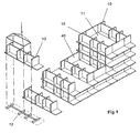
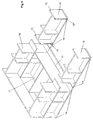
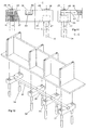
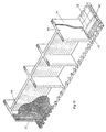
- the volumetric modular building system comprises a matched pair of reinforced concrete inverted tee-beam modules with integral crosswalls 10, a suspended concrete floor assembly 11 and infill panels 40.
- primary crosswalls are fitted with four removable primary gauge legs 13 configured, in plan, to resemble a standard ISO freight container.
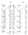
- Each primary gauge leg 13 comprises a rectangular hollow steel section with a structural 'corner casting' 15 in accordance with ISO-1161-1976, welded at each end.
- Plate shear connectors 16 are welded to inside faces for extra strength and security during lifting.
- Secondary gauge legs 18, having plain ends, are similarly affixed to the outside edges of remaining crosswalls during manufacture in order to locate bearings and tie-rod sleeves and also to control formwork geometry.
- All gauge legs have provision for threaded nut and bolt attachment of 'cup and cone' formwork ties 17 which are connected to waved and threaded rebar anchors 19 cast permanently within the ends of the concrete crosswalls. Before casting, anchors 19 are spot-welded to each vertical tie-rod sleeve 20 which support the top and bottom bearing plates 21 & 22 respectively. All cups, cones and gauge legs are eventually removed for re-use.
- the means of regulating, securing and fixing the modules in position, one upon another or onto foundations 12, is achieved through bedded bearings comprising the top and bottom steel bearing plates 21 & 22, shims 38, and intermediate cementitious mortar padding 23.
- the vertical tie-rods 24 are progressively jointed during loading operations using threaded couplings 25 and are later tensioned and grouted 26, if required.
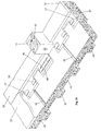
- Module floor edges have notched wedge-shaped pockets 27 formed in order to accommodate steel hangers 28 which support precast beams 29 ('double-tee' or similar floor elements 45) and concrete block insertions 30.
- Precast beams of deeper section 31 are used for room thresholds, balcony and walkway edges having welded steel hanger connectors 46.
- screed material 32 is laid over the entire suspended floor thereby covering peripheral and intermediate tendons 39, and filling gaps between wedge-shaped pockets, steel hangers, blocks and beams.
- module floor construction with wider suspended floors of deeper section with female threaded reinforcement connectors 14 for a 'cast-in-place' concrete floor is shown.
- the precast concrete foundation arrangement 12 comprises 'augured or driven piles' 34, precast concrete capping beams 35, the secondary precast concrete connecting-beams 36 and welded threaded couplings 25.
- Capping beams comprise plain reinforced concrete with a pair of cone-shaped voids 47 at their under-sides. Top extremities have embedded steel plates 48 which serve as the initial bearing surfaces for the modules and intermediate shims 38.
- a central rebate has a steel plate embedment 49 acting as a bearing for, and weld attachment to, the connecting-beam corner steel angle 50.
- Connecting beams each have a duct 51, cast in along a central axis to accommodate stressed tendons for longitudinal continuity.
- Modules, suspended floor and foundation elements are composed of monolithically-formed dense concrete and high-tensile steel reinforcement 37 and the various embedments for structural integrity described above.
Landscapes
- Engineering & Computer Science (AREA)
- Architecture (AREA)
- Physics & Mathematics (AREA)
- Electromagnetism (AREA)
- Civil Engineering (AREA)
- Structural Engineering (AREA)
- Conveying And Assembling Of Building Elements In Situ (AREA)
- Buildings Adapted To Withstand Abnormal External Influences (AREA)
- Joining Of Building Structures In Genera (AREA)
- External Artificial Organs (AREA)
Claims (24)
- Verfahren zum Herstellen eines tragfähigen verstärkten volumetrischen Betonmoduls als einstückiges Gußteil aus einer Struktur aus Trägern mit umgekehrtem T-Profil mit integralen scherkraftaufnehmenden Querwand- (10) und Bodenelementen, wobei während des Gießprozesses Stahlelemente (17, 19) in den Beton derart eingebettet werden, daß sie davon hervorstehen, um beim Anheben des Moduls als Anker oder Verankerungen verwendet zu werden;
dadurch gekennzeichnet, daß
mindestens einige der Querwandelemente (10) gegossen werden, während die Stahlankerelemente (17, 19) in ihren jeweiligen Enden eingebettet sind; und
die Endextremitäten dieser Wandelemente (10) für den Gießprozeß jeweils durch längliche Hebeschenkel (13, 15) aus Stahl definiert sind, die während des gesamten Gießprozesses an den Stahlankerelementen (17, 19) lösbar befestigt bleiben. - Verfahren nach Anspruch 1, wobei jeder Hebeschenkel ein längliches Stahlelement (13) mit einem hohlen rechtekkigen Querschnitt und an jedem Ende des Stahlelements (13) befestigte Randbefestigungselemente (15) aufweist.
- Verfahren nach Anspruch 1 oder 2, wobei plattenförmige Verbundanker (16) an der Innenseite jedes Schenkels (13, 15) befestigt sind, um die Hebefestigkeit des Moduls zu erhöhen.
- Verfahren nach einem der Ansprüche 1 bis 3, wobei Buchsen (20) für vertikale Zugstangen (24) und mit einer oberen und einer unteren Lagerplatte (22, 21) während des Gießprozesses in der Nähe der jeweiligen Endextremitäten der Querwandelemente (10) in die Querwandelemente (10) eingebettet werden.
- Verfahren nach Anspruch 4, wobei nach dem Gießvorgang mit Gewinde versehene Zugstangen (24) in die Zugstangenbuchsen (20) eingesetzt werden.
- Verfahren nach Anspruch 4 oder 5, wobei die Ankerelemente (17, 19) vor dem Gießprozeß an den Zugstangenbuchsen (20) ihrer zugeordneten Querwandelementenden befestigt werden.
- Verfahren nach einem der Ansprüche 1 bis 6, wobei die Endextremitäten nur einiger der Querwandelemente (10) wie vorstehend erwähnt durch die Hebeschenkel (13, 15) definiert sind, und wobei die Endextremitäten der anderen Querwandelemente (10) für den Gießprozeß jeweils durch andere längliche Stahlschenkel (18) definiert sind, die während des gesamten Prozesses an den Ankerelementen (17, 19) dieser anderen Querwandelemente (10) lösbar befestigt bleiben.
- Verfahren nach Anspruch 7, wobei jeder der anderen Schenkel ein längliches Stahlelement (18) mit einem hohlen rechteckigen Querschnitt aufweist.
- Verfahren nach einem der Ansprüche 1 bis 8, wobei die Bodenelementränder des Moduls in dem Prozeß mit keilförmigen Taschen (27) im Bodenelementrand gegossen werden, um jeweils Hängelager (28) aufzunehmen, die die Enden von Hängebodenträgern (29) halten.
- Verfahren nach einem der Ansprüche 1 bis 9, wobei während des Gießprozesses horizontale Buchsen für Vorspannglieder (39) im Bodenelement des Moduls eingebettet werden.
- Verfahren nach einem der Ansprüche 1 bis 10, wobei während des Gießprozesses Rohrleitungen für ein Heiz/Kühlsystem (44) in den Beton eingebettet werden.
- Verfahren nach einem der Ansprüche 1 bis 11, wobei die Breite des Moduls, die zwischen den Außenflächen der Hebeschenkel (13, 15) definiert ist, 8 Fuß (2428 mm) beträgt, so daß sie der Breite für Frachtcontainer nach ISO Standard Serie 1 entspricht.
- Tragfähiges verstärktes volumetrisches Betonmodul in der Form eines einteiligen Gußteils aus einer Struktur aus Trägern mit umgekehrtem T-Profil mit integralen scherkraftaufnehmenden Querwandelementen (10) und Bodenelementen, wobei in den Gußbeton eingebettete Stahlelemente (17, 19) davon hervorstehen, um beim Anheben des Moduls als Anker verwendet zu werden;
dadurch gekennzeichnet, daß
die Stahlankerelemente (17, 19) in den Enden mindestens einiger der Querwandelemente (10) eingebettet sind; und
längliche Hebeschenkel (13, 15) aus Stahl an den Stahlankerelementen (17, 19) dieser jeweiligen Wandelemente (10) lösbar befestigt sind, um ihre Endextremitäten zu definieren. - Modul nach Anspruch 13, wobei jeder Hebeschenkel ein längliches Stahlelement (13) mit einem hohlen rechtekkigen Querschnitt und an jedem Ende des Stahlelements (13) befestigte Randbefestigungselemente (15) aufweist.
- Modul nach Anspruch 13 oder 14, wobei plattenförmige Verbundanker (16) an der Innenseite jedes Schenkels (13, 15) befestigt sind, um die Hebefestigkeit des Moduls zu erhöhen.
- Modul nach einem der Ansprüche 13 bis 15, wobei Buchsen (20) für vertikale Zugstangen (24) und mit einer oberen und einer unteren Lagerplatte (22, 21) in der Nähe der jeweiligen Endextremitäten der Querwandelemente (10) in die Querwandelemente (10) eingebettet sind.
- Modul nach Anspruch 16 mit in die Zugstangenbuchsen (20) eingesetzten, mit Gewinde versehenen Zugstangen (24).
- Modul nach Anspruch 16 oder 17, wobei die Ankerelemente (17, 19) an den Zugstangenbuchsen (20) ihrer jeweiligen Querwandelementenden angeschweißt sind.
- Modul nach einem der Ansprüche 13 bis 18, wobei nur einige der Querwandelemente (10) des Moduls daran lösbar befestigte Hebeschenkel (13, 15) aufweisen und die Endextremitäten der anderen Querwandelemente (10) jeweils durch andere längliche Stahlschenkel (18) definiert sind, die an Ankerelementen (17, 19) lösbar befestigt sind, die in den anderen Querwandelementen (10) eingebettet sind.
- Modul nach Anspruch 19, wobei jeder der anderen Schenkel ein längliches Stahlelement (18) mit einem hohlen rechteckigen Abschnitt aufweist.
- Modul nach einem der Ansprüche 13 bis 20, wobei die Bodenelementränder des Moduls mit keilförmigen Taschen (27) im Bodenelementrand gegossen sind, um jeweilige Hängelager (28) aufzunehmen, die die Enden von Trägern (29) eines aufgehängten Boden- oder Geschoßelements halten.
- Modul nach einem der Ansprüche 13 bis 21, wobei horizontale Buchsen für Vorspannglieder (39) im Bodenelement des Moduls eingebettet sind.
- Modul nach einem der Ansprüche 13 bis 22, wobei Rohrleitungen für ein Heiz-/Kühlsystem (44) in den Beton eingebettet sind.
- Modul nach einem der Ansprüche 13 bis 23, wobei die Breite des Moduls, die zwischen den Außenflächen der Hebeschenkel (13, 15) definiert ist, 8 Fuß (2428 mm) beträgt, so daß sie der Breite für Frachtcontainer nach ISO Standard Serie 1 entspricht.
Applications Claiming Priority (3)
| Application Number | Priority Date | Filing Date | Title |
|---|---|---|---|
| GB9822784 | 1998-10-20 | ||
| GBGB9822784.6A GB9822784D0 (en) | 1998-10-20 | 1998-10-20 | Volumetric modular building system |
| PCT/GB1999/003519 WO2000023666A1 (en) | 1998-10-20 | 1999-10-19 | Volumetric modular building system |
Publications (2)
| Publication Number | Publication Date |
|---|---|
| EP1123449A1 EP1123449A1 (de) | 2001-08-16 |
| EP1123449B1 true EP1123449B1 (de) | 2005-04-06 |
Family
ID=10840832
Family Applications (1)
| Application Number | Title | Priority Date | Filing Date |
|---|---|---|---|
| EP99950972A Expired - Lifetime EP1123449B1 (de) | 1998-10-20 | 1999-10-19 | Volumetrisches modulbausystem |
Country Status (8)
| Country | Link |
|---|---|
| US (1) | US6658799B1 (de) |
| EP (1) | EP1123449B1 (de) |
| KR (1) | KR100743913B1 (de) |
| AT (1) | ATE292717T1 (de) |
| AU (1) | AU6355899A (de) |
| DE (1) | DE69924633T2 (de) |
| GB (1) | GB9822784D0 (de) |
| WO (1) | WO2000023666A1 (de) |
Cited By (2)
| Publication number | Priority date | Publication date | Assignee | Title |
|---|---|---|---|---|
| CN106245827A (zh) * | 2016-08-30 | 2016-12-21 | 中建八局第四建设有限公司 | 一种剪力墙施工方法 |
| CN112060270A (zh) * | 2020-07-15 | 2020-12-11 | 山东泰迅装配式建筑科技有限公司 | 一种ppvc模块通过外模浇筑成型的方法 |
Families Citing this family (37)
| Publication number | Priority date | Publication date | Assignee | Title |
|---|---|---|---|---|
| WO2002064900A1 (en) * | 2001-02-14 | 2002-08-22 | Gammon Finance Limited | Modular structure |
| KR100447056B1 (ko) * | 2001-11-10 | 2004-09-04 | 이인태 | 육각구조의 다가구주택 |
| KR200384762Y1 (ko) * | 2004-12-01 | 2005-05-24 | 한광석 | 조립식 석재가옥 |
| US7237362B2 (en) * | 2005-04-18 | 2007-07-03 | Bishop Richard B | Safe room |
| CA2511355A1 (en) * | 2005-06-28 | 2006-12-28 | Andreas Froese | Modular containment system |
| KR100764024B1 (ko) * | 2007-01-30 | 2007-10-05 | (주)이에스연구소 | 모듈러 구조물의 단위모듈에서 기둥 내부에 수평스티프너를사용한 보와 기둥의 강접합구조 |
| US8910439B2 (en) | 2007-04-11 | 2014-12-16 | M3house, LLC | Wall panels for affordable, sustainable buildings |
| US8429871B2 (en) | 2007-04-11 | 2013-04-30 | Erla Dögg Ingjaldsdottir | Affordable, sustainable buildings comprised of recyclable materials and methods thereof |
| US7941975B2 (en) * | 2007-04-11 | 2011-05-17 | Erla Dogg Ingjaldsdottir | Affordable, sustainable buildings comprised of recyclable materials and methods thereof |
| KR100764025B1 (ko) * | 2007-06-12 | 2007-10-05 | (주)이에스연구소 | 연결구가 구비된 수평 유닛 및 이를 이용한 모듈러 구조물 |
| US8166714B2 (en) | 2007-10-04 | 2012-05-01 | Ziegelman Robert L | Buildings formed of a plurality of prefabricated modules |
| WO2009061702A1 (en) * | 2007-11-06 | 2009-05-14 | Framemax, Inc. | Modular building construction unit, system, and method |
| CA2615154C (en) * | 2007-11-20 | 2012-06-19 | Bcm Developments Ltd. | Method of building construction |
| US7882659B2 (en) * | 2008-04-23 | 2011-02-08 | Modular Container Solutions Llc | Modular assembly |
| US8347560B2 (en) | 2008-04-23 | 2013-01-08 | Modular Container Solutions Llc | Modular assembly |
| US20100024353A1 (en) | 2008-07-29 | 2010-02-04 | Green Horizon Manufacturing Llc | Method for deploying prefabricated structures arranged in a complementary layout |
| US20100107520A1 (en) * | 2008-09-26 | 2010-05-06 | Lundmark Bo J | Structural shearwall |
| US8074414B2 (en) * | 2009-01-20 | 2011-12-13 | Skidmore Owings & Merrill Llp | Precast wall panels and method of erecting a high-rise building using the panels |
| US8631616B2 (en) | 2009-01-20 | 2014-01-21 | Skidmore Owings & Merrill Llp | Precast wall panels and method of erecting a high-rise building using the panels |
| WO2010151539A1 (en) | 2009-06-22 | 2010-12-29 | Barnet Liberman | Modular building system for constructing multi-story buildings |
| US20120090254A1 (en) * | 2010-10-14 | 2012-04-19 | Mr. Venkata Rangarao Vemuri | Method of forming flat strip stepped slab floor system of reinforced concrete |
| CN102888932A (zh) * | 2011-07-18 | 2013-01-23 | 湖南邱则有专利战略策划有限公司 | 装配式空腹网格板楼盖 |
| FI127276B (en) | 2013-12-31 | 2018-02-28 | Arkkitehtitoimisto Karin Krokfors Oy | Vertical channel element, frame structure and building |
| DE102015113484A1 (de) * | 2015-08-14 | 2017-02-16 | Bernd Iglauer | Flächiges Bauelement, aussteifende Scheibe, Gebäudemodul und mehrstöckiges Gebäude |
| SG10201908614WA (en) | 2016-06-28 | 2019-10-30 | Seng Wong | Composite structural wall and method of construction thereof |
| CN106499089B (zh) * | 2016-11-03 | 2018-08-31 | 北京工业大学 | 底部加强型高强混凝土组合剪力墙及制作方法 |
| CN106337512B (zh) * | 2016-11-03 | 2018-05-29 | 北京工业大学 | 底部加强型钢管混凝土边框高强混凝土组合剪力墙及制作方法 |
| CA3033991A1 (en) | 2018-02-13 | 2018-04-26 | Michael A. Dombowsky | Prefabricated insulated building panel with opposite cured cementitious layers bonded to insulation |
| WO2019221665A1 (en) * | 2018-05-17 | 2019-11-21 | Kcl Consultants Pte Ltd | Ppvc connector |
| RU2678750C1 (ru) * | 2018-08-23 | 2019-01-31 | Публичное акционерное общество "ИНГРАД" | Способ возведения зданий и сооружений с несущими монолитными железобетонными конструкциями с применением железобетонных стеновых панелей |
| CN110042946A (zh) * | 2019-04-30 | 2019-07-23 | 山东汇源杭萧钢构有限公司 | 装配式剪力墙及其施工方法 |
| US11214964B2 (en) * | 2019-06-14 | 2022-01-04 | Nexii Building Solutions Inc. | Reinforced structural insulation panel with corner blocks |
| US11692341B2 (en) * | 2020-07-22 | 2023-07-04 | Nano And Advanced Materials Institute Limited | Lightweight concrete modular integrated construction (MIC) system |
| KR102203580B1 (ko) * | 2020-09-11 | 2021-01-15 | 조용호 | Pc패널을 이용한 주택 시공방법 |
| CN117988601B (zh) * | 2024-04-07 | 2024-07-02 | 成都中品建设工程有限公司 | 一种装配式功能性建筑及其施工方法 |
| US20250347107A1 (en) * | 2024-05-08 | 2025-11-13 | 3Jr, Llc | Systems and methods for building elevated structures |
| US12509874B2 (en) * | 2024-05-24 | 2025-12-30 | Stack Racks, LLC | Container stacking for housing |
Family Cites Families (19)
| Publication number | Priority date | Publication date | Assignee | Title |
|---|---|---|---|---|
| US3952474A (en) * | 1969-06-02 | 1976-04-27 | Rice Edward K | Method of assembling building structures |
| US3724141A (en) * | 1970-01-15 | 1973-04-03 | M Kelleher | Modular units, buildings and systems |
| FR2095412A5 (de) * | 1970-03-02 | 1972-02-11 | Berce Jacques | |
| US3703058A (en) * | 1970-09-14 | 1972-11-21 | Building Block Modules Inc | Modular building construction and erection system utilizing selectively oriented modules |
| US3952465A (en) | 1971-03-19 | 1976-04-27 | Dominic Joseph Masiello | Building structure formed of modular units with cantilevered portions for forming a corridor floor |
| US3742660A (en) | 1972-04-03 | 1973-07-03 | R Bierweiler | Building construction |
| US4136492A (en) * | 1973-06-04 | 1979-01-30 | Willingham John H | Industrialized building construction |
| US4147009A (en) * | 1975-12-04 | 1979-04-03 | Watry C Nicholas | Precast panel building construction |
| US4282690A (en) * | 1979-08-23 | 1981-08-11 | Meheen H Joe | Precast building construction |
| FR2472649A1 (fr) * | 1979-12-28 | 1981-07-03 | Balzer Edmond | Realisation d'un encastrement provisoirement independant d'une piece prefabriquee en beton dans son systeme de fondation |
| KR890000681B1 (ko) * | 1981-12-02 | 1989-03-24 | 미사와 호오무 가부시끼가이샤 | 건축 유니트에 의한 건물의 구축법 |
| US5081805A (en) * | 1989-08-23 | 1992-01-21 | Jazzar M Omar A | Precast concrete building units and method of manufacture thereof |
| US5402618A (en) * | 1991-12-31 | 1995-04-04 | Cable Bridge Enterprises Limited | System for use in fabricating, transporting and placing a prefabricated building unit at its placement site |
| US5203707A (en) * | 1992-01-06 | 1993-04-20 | Symtron Systems Inc | Modular fire trainer |
| BE1008118A3 (fr) * | 1994-03-18 | 1996-01-23 | Rebuild World Rbw Sa | Dalle flottante, procede pour sa realisation et batiment comportant au moins une telle dalle flottante. |
| US5493817A (en) * | 1994-08-22 | 1996-02-27 | Speer; Jerry | Mobile workshop and method of configuring same |
| JPH1014056A (ja) * | 1996-06-18 | 1998-01-16 | Nissin Electric Co Ltd | 柱上照明灯の接続装置 |
| KR100220138B1 (ko) * | 1996-08-07 | 1999-09-01 | 박광진 | 조립건물의 시공법 및 그 조립부재 |
| US6367205B2 (en) * | 1998-10-05 | 2002-04-09 | Hurri-Bolt, Inc. | Anchor for a structural tie-down apparatus |
-
1998
- 1998-10-20 GB GBGB9822784.6A patent/GB9822784D0/en not_active Ceased
-
1999
- 1999-10-19 EP EP99950972A patent/EP1123449B1/de not_active Expired - Lifetime
- 1999-10-19 DE DE69924633T patent/DE69924633T2/de not_active Expired - Fee Related
- 1999-10-19 US US09/807,862 patent/US6658799B1/en not_active Expired - Fee Related
- 1999-10-19 AT AT99950972T patent/ATE292717T1/de not_active IP Right Cessation
- 1999-10-19 AU AU63558/99A patent/AU6355899A/en not_active Abandoned
- 1999-10-19 WO PCT/GB1999/003519 patent/WO2000023666A1/en not_active Ceased
- 1999-10-19 KR KR1020017004907A patent/KR100743913B1/ko not_active Expired - Fee Related
Cited By (2)
| Publication number | Priority date | Publication date | Assignee | Title |
|---|---|---|---|---|
| CN106245827A (zh) * | 2016-08-30 | 2016-12-21 | 中建八局第四建设有限公司 | 一种剪力墙施工方法 |
| CN112060270A (zh) * | 2020-07-15 | 2020-12-11 | 山东泰迅装配式建筑科技有限公司 | 一种ppvc模块通过外模浇筑成型的方法 |
Also Published As
| Publication number | Publication date |
|---|---|
| AU6355899A (en) | 2000-05-08 |
| KR20010089315A (ko) | 2001-09-29 |
| EP1123449A1 (de) | 2001-08-16 |
| WO2000023666A1 (en) | 2000-04-27 |
| KR100743913B1 (ko) | 2007-07-30 |
| US6658799B1 (en) | 2003-12-09 |
| GB9822784D0 (en) | 1998-12-16 |
| DE69924633T2 (de) | 2006-01-19 |
| ATE292717T1 (de) | 2005-04-15 |
| DE69924633D1 (de) | 2005-05-12 |
Similar Documents
| Publication | Publication Date | Title |
|---|---|---|
| US6658799B1 (en) | Volumetric modular building system | |
| US4147009A (en) | Precast panel building construction | |
| US4219978A (en) | Pre-cast reinforced concrete building panel wall structure | |
| US4454702A (en) | Building construction and method of constructing same | |
| AU2022204051B2 (en) | Method for constructing a concrete floor in a multistorey building | |
| CN110042862B (zh) | 地铁车站预制轨顶风道、与预制中板连接节点及施工方法 | |
| CN103797197B (zh) | 预铸整体式墙与楼板的建筑结构 | |
| AU2017304226B2 (en) | Precast concrete formwork, floor system and a method of construction | |
| EP4010538B1 (de) | Vorgegossene bauplatte | |
| US7121061B2 (en) | Reinforced concrete building system | |
| CA2297972C (en) | Building panels for use in the construction of buildings | |
| HK1244857B (en) | Composite structural wall and method of construction thereof | |
| CN103422672A (zh) | 一种钢筋混凝土预制装配式房屋施工建造方法 | |
| CA3109393C (en) | Precast building construction system | |
| CN212453065U (zh) | 装配式建筑框架结构构件 | |
| KR200178874Y1 (ko) | 조립식 pc콘크리트 벽체판넬 | |
| US7073300B1 (en) | Reinforced concrete part for producing foundations of buildings | |
| CN222909569U (zh) | 一种全装配式混凝土多层建筑体系 | |
| EP4352309B1 (de) | Fundamentstruktur für konstruktionen | |
| US20260015850A1 (en) | Method for using aerated autoclaved concrete in residential and commercial construction | |
| CN219931248U (zh) | 装配式钢结构外挂预制墙体与地下室顶板连接构造 | |
| RU2037608C1 (ru) | Способ строительства многоэтажных зданий из объемных блоков | |
| CN109252681B (zh) | 一种屋顶预制件的防震安装方法 | |
| CN120331405A (zh) | 预制石膏墙板连接节点结构及施工方法 | |
| AU784738B2 (en) | Building system and prefabricated wall panels |
Legal Events
| Date | Code | Title | Description |
|---|---|---|---|
| PUAI | Public reference made under article 153(3) epc to a published international application that has entered the european phase |
Free format text: ORIGINAL CODE: 0009012 |
|
| 17P | Request for examination filed |
Effective date: 20010517 |
|
| AK | Designated contracting states |
Kind code of ref document: A1 Designated state(s): AT BE CH CY DE DK ES FI FR GB GR IE IT LI LU MC NL PT SE |
|
| AX | Request for extension of the european patent |
Free format text: AL;LT;LV;MK;RO;SI |
|
| 17Q | First examination report despatched |
Effective date: 20030207 |
|
| GRAP | Despatch of communication of intention to grant a patent |
Free format text: ORIGINAL CODE: EPIDOSNIGR1 |
|
| GRAS | Grant fee paid |
Free format text: ORIGINAL CODE: EPIDOSNIGR3 |
|
| GRAA | (expected) grant |
Free format text: ORIGINAL CODE: 0009210 |
|
| AK | Designated contracting states |
Kind code of ref document: B1 Designated state(s): AT BE CH CY DE DK ES FI FR GB GR IE IT LI LU MC NL PT SE |
|
| PG25 | Lapsed in a contracting state [announced via postgrant information from national office to epo] |
Ref country code: LI Free format text: LAPSE BECAUSE OF FAILURE TO SUBMIT A TRANSLATION OF THE DESCRIPTION OR TO PAY THE FEE WITHIN THE PRESCRIBED TIME-LIMIT Effective date: 20050406 Ref country code: IT Free format text: LAPSE BECAUSE OF FAILURE TO SUBMIT A TRANSLATION OF THE DESCRIPTION OR TO PAY THE FEE WITHIN THE PRE;WARNING: LAPSES OF ITALIAN PATENTS WITH EFFECTIVE DATE BEFORE 2007 MAY HAVE OCCURRED AT ANY TIME BEFORE 2007. THE CORRECT EFFECTIVE DATE MAY BE DIFFERENT FROM THE ONE RECORDED.SCRIBED TIME-LIMIT Effective date: 20050406 Ref country code: FI Free format text: LAPSE BECAUSE OF FAILURE TO SUBMIT A TRANSLATION OF THE DESCRIPTION OR TO PAY THE FEE WITHIN THE PRESCRIBED TIME-LIMIT Effective date: 20050406 Ref country code: CH Free format text: LAPSE BECAUSE OF FAILURE TO SUBMIT A TRANSLATION OF THE DESCRIPTION OR TO PAY THE FEE WITHIN THE PRESCRIBED TIME-LIMIT Effective date: 20050406 Ref country code: BE Free format text: LAPSE BECAUSE OF FAILURE TO SUBMIT A TRANSLATION OF THE DESCRIPTION OR TO PAY THE FEE WITHIN THE PRESCRIBED TIME-LIMIT Effective date: 20050406 Ref country code: AT Free format text: LAPSE BECAUSE OF FAILURE TO SUBMIT A TRANSLATION OF THE DESCRIPTION OR TO PAY THE FEE WITHIN THE PRESCRIBED TIME-LIMIT Effective date: 20050406 |
|
| REG | Reference to a national code |
Ref country code: GB Ref legal event code: FG4D |
|
| REG | Reference to a national code |
Ref country code: CH Ref legal event code: EP |
|
| REG | Reference to a national code |
Ref country code: IE Ref legal event code: FG4D |
|
| REF | Corresponds to: |
Ref document number: 69924633 Country of ref document: DE Date of ref document: 20050512 Kind code of ref document: P |
|
| PG25 | Lapsed in a contracting state [announced via postgrant information from national office to epo] |
Ref country code: SE Free format text: LAPSE BECAUSE OF FAILURE TO SUBMIT A TRANSLATION OF THE DESCRIPTION OR TO PAY THE FEE WITHIN THE PRESCRIBED TIME-LIMIT Effective date: 20050706 Ref country code: GR Free format text: LAPSE BECAUSE OF FAILURE TO SUBMIT A TRANSLATION OF THE DESCRIPTION OR TO PAY THE FEE WITHIN THE PRESCRIBED TIME-LIMIT Effective date: 20050706 Ref country code: DK Free format text: LAPSE BECAUSE OF FAILURE TO SUBMIT A TRANSLATION OF THE DESCRIPTION OR TO PAY THE FEE WITHIN THE PRESCRIBED TIME-LIMIT Effective date: 20050706 |
|
| PG25 | Lapsed in a contracting state [announced via postgrant information from national office to epo] |
Ref country code: ES Free format text: LAPSE BECAUSE OF FAILURE TO SUBMIT A TRANSLATION OF THE DESCRIPTION OR TO PAY THE FEE WITHIN THE PRESCRIBED TIME-LIMIT Effective date: 20050717 |
|
| PG25 | Lapsed in a contracting state [announced via postgrant information from national office to epo] |
Ref country code: PT Free format text: LAPSE BECAUSE OF FAILURE TO SUBMIT A TRANSLATION OF THE DESCRIPTION OR TO PAY THE FEE WITHIN THE PRESCRIBED TIME-LIMIT Effective date: 20050908 |
|
| REG | Reference to a national code |
Ref country code: CH Ref legal event code: PL |
|
| PG25 | Lapsed in a contracting state [announced via postgrant information from national office to epo] |
Ref country code: CY Free format text: LAPSE BECAUSE OF FAILURE TO SUBMIT A TRANSLATION OF THE DESCRIPTION OR TO PAY THE FEE WITHIN THE PRESCRIBED TIME-LIMIT Effective date: 20051019 |
|
| PG25 | Lapsed in a contracting state [announced via postgrant information from national office to epo] |
Ref country code: MC Free format text: LAPSE BECAUSE OF NON-PAYMENT OF DUE FEES Effective date: 20051031 Ref country code: LU Free format text: LAPSE BECAUSE OF NON-PAYMENT OF DUE FEES Effective date: 20051031 |
|
| PGFP | Annual fee paid to national office [announced via postgrant information from national office to epo] |
Ref country code: GB Payment date: 20051118 Year of fee payment: 7 |
|
| PLBE | No opposition filed within time limit |
Free format text: ORIGINAL CODE: 0009261 |
|
| STAA | Information on the status of an ep patent application or granted ep patent |
Free format text: STATUS: NO OPPOSITION FILED WITHIN TIME LIMIT |
|
| 26N | No opposition filed |
Effective date: 20060110 |
|
| ET | Fr: translation filed | ||
| GBPC | Gb: european patent ceased through non-payment of renewal fee |
Effective date: 20061019 |
|
| PG25 | Lapsed in a contracting state [announced via postgrant information from national office to epo] |
Ref country code: GB Free format text: LAPSE BECAUSE OF NON-PAYMENT OF DUE FEES Effective date: 20061019 |
|
| PGFP | Annual fee paid to national office [announced via postgrant information from national office to epo] |
Ref country code: NL Payment date: 20071031 Year of fee payment: 9 Ref country code: DE Payment date: 20071129 Year of fee payment: 9 |
|
| PGFP | Annual fee paid to national office [announced via postgrant information from national office to epo] |
Ref country code: FR Payment date: 20071030 Year of fee payment: 9 |
|
| NLV4 | Nl: lapsed or anulled due to non-payment of the annual fee |
Effective date: 20090501 |
|
| REG | Reference to a national code |
Ref country code: IE Ref legal event code: MM4A |
|
| REG | Reference to a national code |
Ref country code: FR Ref legal event code: ST Effective date: 20090630 |
|
| PG25 | Lapsed in a contracting state [announced via postgrant information from national office to epo] |
Ref country code: NL Free format text: LAPSE BECAUSE OF NON-PAYMENT OF DUE FEES Effective date: 20090501 |
|
| PG25 | Lapsed in a contracting state [announced via postgrant information from national office to epo] |
Ref country code: DE Free format text: LAPSE BECAUSE OF NON-PAYMENT OF DUE FEES Effective date: 20090501 |
|
| PGFP | Annual fee paid to national office [announced via postgrant information from national office to epo] |
Ref country code: IE Payment date: 20071029 Year of fee payment: 9 |
|
| PG25 | Lapsed in a contracting state [announced via postgrant information from national office to epo] |
Ref country code: IE Free format text: LAPSE BECAUSE OF NON-PAYMENT OF DUE FEES Effective date: 20081020 Ref country code: FR Free format text: LAPSE BECAUSE OF NON-PAYMENT OF DUE FEES Effective date: 20081031 |