EP1123489B1 - Dispositif de mesure capacitif - Google Patents
Dispositif de mesure capacitif Download PDFInfo
- Publication number
- EP1123489B1 EP1123489B1 EP99949088A EP99949088A EP1123489B1 EP 1123489 B1 EP1123489 B1 EP 1123489B1 EP 99949088 A EP99949088 A EP 99949088A EP 99949088 A EP99949088 A EP 99949088A EP 1123489 B1 EP1123489 B1 EP 1123489B1
- Authority
- EP
- European Patent Office
- Prior art keywords
- probe
- measuring probe
- measuring
- voltage
- stage
- Prior art date
- Legal status (The legal status is an assumption and is not a legal conclusion. Google has not performed a legal analysis and makes no representation as to the accuracy of the status listed.)
- Expired - Lifetime
Links
- 239000000523 sample Substances 0.000 claims abstract description 249
- 238000005259 measurement Methods 0.000 claims abstract description 110
- 239000003990 capacitor Substances 0.000 claims abstract description 35
- 125000004122 cyclic group Chemical group 0.000 claims abstract 2
- 238000012545 processing Methods 0.000 claims description 19
- 238000001228 spectrum Methods 0.000 claims description 15
- 238000012937 correction Methods 0.000 claims description 12
- 239000012530 fluid Substances 0.000 claims description 9
- 239000004020 conductor Substances 0.000 claims description 7
- 239000011248 coating agent Substances 0.000 claims description 6
- 238000000576 coating method Methods 0.000 claims description 6
- 238000004364 calculation method Methods 0.000 claims description 4
- 230000005684 electric field Effects 0.000 claims description 4
- 230000010354 integration Effects 0.000 claims description 4
- 230000001360 synchronised effect Effects 0.000 claims description 3
- 238000007493 shaping process Methods 0.000 claims description 2
- 238000012546 transfer Methods 0.000 claims description 2
- 238000001514 detection method Methods 0.000 description 34
- 239000000047 product Substances 0.000 description 19
- XLYOFNOQVPJJNP-UHFFFAOYSA-N water Substances O XLYOFNOQVPJJNP-UHFFFAOYSA-N 0.000 description 7
- 230000000694 effects Effects 0.000 description 6
- 239000007788 liquid Substances 0.000 description 6
- 239000007789 gas Substances 0.000 description 5
- 239000000463 material Substances 0.000 description 5
- 238000006073 displacement reaction Methods 0.000 description 4
- 238000009413 insulation Methods 0.000 description 4
- 239000012528 membrane Substances 0.000 description 4
- 239000002184 metal Substances 0.000 description 3
- 230000003595 spectral effect Effects 0.000 description 3
- 241001080024 Telles Species 0.000 description 2
- 238000004458 analytical method Methods 0.000 description 2
- 238000013459 approach Methods 0.000 description 2
- 239000012777 electrically insulating material Substances 0.000 description 2
- 239000003915 liquefied petroleum gas Substances 0.000 description 2
- 238000000034 method Methods 0.000 description 2
- 230000003472 neutralizing effect Effects 0.000 description 2
- 210000000056 organ Anatomy 0.000 description 2
- 239000003209 petroleum derivative Substances 0.000 description 2
- 239000004033 plastic Substances 0.000 description 2
- 229920003023 plastic Polymers 0.000 description 2
- 239000004800 polyvinyl chloride Substances 0.000 description 2
- 239000000843 powder Substances 0.000 description 2
- 238000005070 sampling Methods 0.000 description 2
- 101100536354 Drosophila melanogaster tant gene Proteins 0.000 description 1
- 241001415961 Gaviidae Species 0.000 description 1
- 230000005540 biological transmission Effects 0.000 description 1
- 238000004891 communication Methods 0.000 description 1
- 230000009849 deactivation Effects 0.000 description 1
- 238000011161 development Methods 0.000 description 1
- 230000018109 developmental process Effects 0.000 description 1
- 238000007599 discharging Methods 0.000 description 1
- 229920001971 elastomer Polymers 0.000 description 1
- 239000000806 elastomer Substances 0.000 description 1
- 238000001914 filtration Methods 0.000 description 1
- 239000012212 insulator Substances 0.000 description 1
- 238000002955 isolation Methods 0.000 description 1
- 239000012263 liquid product Substances 0.000 description 1
- 238000004519 manufacturing process Methods 0.000 description 1
- 238000012986 modification Methods 0.000 description 1
- 230000004048 modification Effects 0.000 description 1
- 230000003287 optical effect Effects 0.000 description 1
- 238000010422 painting Methods 0.000 description 1
- 230000035515 penetration Effects 0.000 description 1
- 239000002985 plastic film Substances 0.000 description 1
- 229920000915 polyvinyl chloride Polymers 0.000 description 1
- 238000003908 quality control method Methods 0.000 description 1
- 238000011084 recovery Methods 0.000 description 1
- 230000004044 response Effects 0.000 description 1
- 230000033764 rhythmic process Effects 0.000 description 1
- 230000035945 sensitivity Effects 0.000 description 1
- 239000007787 solid Substances 0.000 description 1
- 239000013589 supplement Substances 0.000 description 1
- 230000008961 swelling Effects 0.000 description 1
- 230000001131 transforming effect Effects 0.000 description 1
- 238000011144 upstream manufacturing Methods 0.000 description 1
- 125000000391 vinyl group Chemical group [H]C([*])=C([H])[H] 0.000 description 1
- 229920002554 vinyl polymer Polymers 0.000 description 1
Images


Classifications
-
- G—PHYSICS
- G01—MEASURING; TESTING
- G01F—MEASURING VOLUME, VOLUME FLOW, MASS FLOW OR LIQUID LEVEL; METERING BY VOLUME
- G01F23/00—Indicating or measuring liquid level or level of fluent solid material, e.g. indicating in terms of volume or indicating by means of an alarm
- G01F23/22—Indicating or measuring liquid level or level of fluent solid material, e.g. indicating in terms of volume or indicating by means of an alarm by measuring physical variables, other than linear dimensions, pressure or weight, dependent on the level to be measured, e.g. by difference of heat transfer of steam or water
- G01F23/26—Indicating or measuring liquid level or level of fluent solid material, e.g. indicating in terms of volume or indicating by means of an alarm by measuring physical variables, other than linear dimensions, pressure or weight, dependent on the level to be measured, e.g. by difference of heat transfer of steam or water by measuring variations of capacity or inductance of capacitors or inductors arising from the presence of liquid or fluent solid material in the electric or electromagnetic fields
- G01F23/263—Indicating or measuring liquid level or level of fluent solid material, e.g. indicating in terms of volume or indicating by means of an alarm by measuring physical variables, other than linear dimensions, pressure or weight, dependent on the level to be measured, e.g. by difference of heat transfer of steam or water by measuring variations of capacity or inductance of capacitors or inductors arising from the presence of liquid or fluent solid material in the electric or electromagnetic fields by measuring variations in capacitance of capacitors
- G01F23/266—Indicating or measuring liquid level or level of fluent solid material, e.g. indicating in terms of volume or indicating by means of an alarm by measuring physical variables, other than linear dimensions, pressure or weight, dependent on the level to be measured, e.g. by difference of heat transfer of steam or water by measuring variations of capacity or inductance of capacitors or inductors arising from the presence of liquid or fluent solid material in the electric or electromagnetic fields by measuring variations in capacitance of capacitors measuring circuits therefor
-
- G—PHYSICS
- G01—MEASURING; TESTING
- G01D—MEASURING NOT SPECIALLY ADAPTED FOR A SPECIFIC VARIABLE; ARRANGEMENTS FOR MEASURING TWO OR MORE VARIABLES NOT COVERED IN A SINGLE OTHER SUBCLASS; TARIFF METERING APPARATUS; MEASURING OR TESTING NOT OTHERWISE PROVIDED FOR
- G01D5/00—Mechanical means for transferring the output of a sensing member; Means for converting the output of a sensing member to another variable where the form or nature of the sensing member does not constrain the means for converting; Transducers not specially adapted for a specific variable
- G01D5/12—Mechanical means for transferring the output of a sensing member; Means for converting the output of a sensing member to another variable where the form or nature of the sensing member does not constrain the means for converting; Transducers not specially adapted for a specific variable using electric or magnetic means
- G01D5/14—Mechanical means for transferring the output of a sensing member; Means for converting the output of a sensing member to another variable where the form or nature of the sensing member does not constrain the means for converting; Transducers not specially adapted for a specific variable using electric or magnetic means influencing the magnitude of a current or voltage
- G01D5/24—Mechanical means for transferring the output of a sensing member; Means for converting the output of a sensing member to another variable where the form or nature of the sensing member does not constrain the means for converting; Transducers not specially adapted for a specific variable using electric or magnetic means influencing the magnitude of a current or voltage by varying capacitance
- G01D5/2405—Mechanical means for transferring the output of a sensing member; Means for converting the output of a sensing member to another variable where the form or nature of the sensing member does not constrain the means for converting; Transducers not specially adapted for a specific variable using electric or magnetic means influencing the magnitude of a current or voltage by varying capacitance by varying dielectric
Definitions
- the present invention relates to the field of sensors.
- the present invention relates to a device for measurement exploiting an indirect measurement of permittivity between two bodies electrically conductive respectively forming a measurement probe and a reference probe.
- a measurement capacitor is connected to an oscillator circuit so that the output frequency of this circuit depends on the capacitance of the capacitor measurement and allows to determine a parameter influencing the permittivity of the capacitor, for example the height of a liquid level contained in a tank in which the measuring capacitor is placed (see for example documents WO-A-98/02718, DE-A-4312432 and DE-A-4434338).
- the present invention now aims to provide new detection means adapted to offer a very large sensitivity.
- Another object of the present invention is to propose means which can be adapted to many applications.
- control means are adapted to apply voltage steps on the measurement probe.
- the device comprises means capable of applying a voltage zero average on the measurement probe.
- the aforementioned operational amplifier receives on a second input, opposite to that intended to be connected sequentially to the measurement, a voltage of opposite sign to the voltage applied by the means supply to the measurement probe.
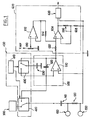
- the measurement probe 100 and the reference probe 200 are formed each of an electrically conductive body. These are spaced apart for define between them at least one dielectric medium. We will describe more in detail, various examples of embodiment of such probes 100 and 200.
- the supply means 300 are adapted to deliver a continuous electrical voltage of controlled amplitude. This amplitude will referenced E.
- the control means 400 are adapted to define cyclically, at a controlled frequency f, a sequence of two sequences.
- a first sequence of duration T1 the supply means 300 are connected to the measurement probe 100 to apply a electric field between measurement probe 100 and reference probe 200 and accumulate electrical charges on the measurement probe 100.
- the means power supply 300 are disconnected from the measurement probe 100 and this is connected to the input of the integrator stage 500.
- the means 400 apply between the measurement probe 100 and the reference 200, a weak impulse electric field of amplitude and duration controlled.
- a mode of deactivation of the electric field applied on the measurement probe 100 blocks electrical charges previously accumulated, on the measurement probe 100.
- the charges present on the measurement probe 100 at the end of the first T1 sequence are proportional to the value of the existing permittivity between probes 100 and 200. They are transferred to the integrator stage 500 (more precisely in the capacity switching system) according to terms which will be specified later. We then get at the exit of this stage 500, a signal representative of the permittivity existing between the measurement probe 100 and reference probe 200.
- the means of command 400 include a time base 410 formed for example an oscillator, and two reversing switches 420, 430.
- the switch 420 controlled by the time base 410, is suitable for alternately connect the measurement probe 100 to the supply means 300 during the T1 sequences, then at the entrance to the integrator stage 500 during T2 sequences.
- a capacitive injector 110 can be inserted between the measurement probe 100 and the switch 420.
- a resistive injector 120 can optionally be placed between the measurement probe 100 and the reference probe 200.
- the resistance of this injector 120 must be very high so as not to create a disturbing leakage current.
- the integrator stage 500 illustrated in FIG. 1 comprises a 510 operational amplifier and two value capacitors respective known: one 520 connected between the inverting input and the output of amplifier 510 and forming feedback on it, the other 530 of which a first electrode is connected to the same potential as the probe reference 200 and the non-inverting input of amplifier 510, i.e. assembly mass, and the second electrode of which is controlled by the control means 400 to be connected alternately to the input amplifier 510 reverser for time T2 (to transfer charges accumulated on the measurement probe 100 in the capacitor 530), then at the output of amplifier 510 for time T1, to deliver an electrical signal proportional to the charges accumulated on the measuring probe 100.
- Capacitor 520 mounted in fixed feedback on operational amplifier 510 transforms the latter into an integrator, collects a DC voltage proportional to the charges developed in the measurement probe 100 and thus to overcome the unwanted interference voltages.
- the integration capacitor 520 has a capacity at less than 1000 times the capacitance of the switching capacitor 530 for an analog type measurement requiring high accuracy, for example example for a level measurement.
- the measurement is not precise, but it allows to follow rapid developments.
- Tilting the measurement probe 100 to a point of summation S of an operational amplifier 510 has two advantages.
- the probe 100 is completely discharged, during time T2, of the charges accumulated, thus putting it back to zero potential for a new measurement during time T1 (this is due to the fact that the summation point (S) of amplifier 510 has zero virtual impedance).
- all of these loads are fully transferred to the switching system capacity 520, 530 and this without loss making the measurement perfectly linear.
- the operation of the integrator stage 500 is the following.
- the capacitor Cs is charged under the supply voltage delivered by the module 300, which is assumed here equal to -E.
- a switching capacitor C530 having a capacity of the same order of magnitude as the capacity Cs defined between the measurement probe 100 and the reference probe 200, ie preferably 0.1 Cs ⁇ C530 ⁇ 10Cs advantageously 0.5 Cs ⁇ C530 ⁇ 5Cs and very advantageously Cs ⁇ C530.
- the frequency f of repetition of the measurement is typically of the order from 5 to 50 kHz.
- the signal available on the output of the integrator stage 500 can be exploited in different ways.
- the output of the operational amplifier 510 is connected, via a resistor 602 at the non-inverting input of an operational amplifier 604. This is mounted on the follower stage.
- the inverting input of operational amplifier 604 is connected to its output via with an adjustable resistance 606.
- the inverting input of the amplifier operational 604 is also connected to ground via a resistance 608.
- the gain of the operational amplifier 604 can be adjusted by the adjustable resistance or potentiometer 606 in order to adjust for example the output voltage of the circuit at the full scale chosen.
- the non-inverting input of the operational amplifier 604 receives also an adjustable counter tension allowing zero adjustment.
- This counter voltage is formed from a voltage VREF of identical preference to that issued at the outlet of the supply means 300.
- This voltage VREF is applied to the terminals of a potentiometer 610 whose adjustable exit point attacks the non-inverting entry of a operational amplifier 612.
- the latter has its inverting input connected to his exit.
- the latter is connected to the non-inverting input of operational amplifier 604 via a resistor 614 of same value as the aforementioned resistor 602. So the non-inverting input of the operational amplifier 604, with very high impedance, receives a against voltage of sign opposite to the measurement slope, to allow the zero adjustment by adjustment on potentiometer 610.
- this counter voltage from the VREF reference voltage applied to the measurement probe 100 allows get rid of any possible drift of this reference voltage.
- the applied counter voltage on the non-inverting input of the operational amplifier 604 drifts in the same direction, thus correcting any risk of zero drift.
- the output of the operational amplifier 604 can be connected to an appropriate 620 operating stage, for example a current loop 4-20mA, or a signal processing stage allowing by example of generating a spectrum characterizing the signal to allow recognize the product analyzed.
- an appropriate 620 operating stage for example a current loop 4-20mA, or a signal processing stage allowing by example of generating a spectrum characterizing the signal to allow recognize the product analyzed.
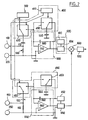
- the device illustrated in this FIG. 2 comprises a probe for measure 100, a reference probe 200, supply means electrical 300, control means 400 and an integrating stage 500 in accordance with the provisions described above with regard to FIG. 1.
- the device illustrated in Figure 2 includes an auxiliary measurement probe 150, an auxiliary reference probe 250, control means auxiliary 450 and an auxiliary integrator stage 550.
- the auxiliary measurement probe and the auxiliary reference probe 150 and 250 are designed to be placed in the same environment as the measurement probe 100 and reference probe 200.
- Auxiliary probes 150 and reference 250 form compensation probes.
- the auxiliary measurement 150 and reference 250 probes can be placed in the lower part of a tank intended to contain a product which one wants measure the level.
- Auxiliary reference probe 250 is placed at the same potential than the reference probe 200.
- the auxiliary control means 450 comprises two reversing switches 452, 453 controlled respectively to the same rhythm than the reversing switches 420, 430 by the time base 410
- the reversing switch 452 during the sequences T1, connects the output of the supply means 300 to the auxiliary measurement probe 150, if necessary, via a capacitive injector 160 and connects the auxiliary measurement probe 150 at the inverting input of an amplifier operational 560 belonging to the integrator stage 550 during the times T2.
- a resistive injector 162 can be placed between the measurement probe 150 and the reference probe 250 auxiliaries, comparable to the 120 resistive injector.
- the integrator stage 550 comprises two capacitors: one referenced 562, homologous to capacitor 520, connected between the input and the output of the operational amplifier 560, the other referenced 564, one terminal of which is connected to ground potential, while the second terminal is connected respectively, by the reversing switch 453, to the output of the operational amplifier 560 during times T1 and at the input amplifier 560 reverser during T2 times.
- the non-inverting input of the 560 amplifier is connected to ground of the assembly.
- This signal can be formatted in an output stage 650 receiving a zero adjustment counter voltage from a stage 652, equivalent to the means 604, 610 essentially described previously for stage 600 opposite FIG. 1.
- stage 650 is here used to control a stage servo control 660 also receiving the output of the setting stage form 600 associated with the main probes 100 and 200, to vary the gain of this control stage 660 in order to make the measurement insensitive to variations in the permittivity of the medium analyzed.
- stage 660 can be connected to any circuit 620, as for example as indicated previously for Figure 1, a 4-20mA current loop or a processing stage, by example able to generate a spectrum characterizing the product analyzed.
- This figure 3 shows a measurement probe 100, a probe reference 200, supply means 300, means of control 400 and an integrator stage 500 in accordance with the provisions previously described with reference to FIG. 1.
- circuit illustrated in FIG. 3 is adapted for neutralize a possible hysteresis effect of accumulated charges on the 100 measurement probe and empty it of all its charges at each cycle controlled by the control means 400.
- the non-inverting input of the operational amplifier 510 is connected not to the potential of the reference probe 200 (i.e. mass), but at sign potential opposite, with respect to the potential of the reference probe 200, to the potential applied by the means 300 to the measurement probe 100.
- the electrical supply means 300 can apply a impulse voltage of amplitude -E on the measurement probe 100, while that the non-inverting input of the operational amplifier 510 is connected to a voltage + E, of the same amplitude but of opposite sign to the voltage supra -E.
- the measurement probe receives by via the reversing switch 420 and the amplifier operational 510, a voltage opposite to that applied during the times T1, able to neutralize the hysteresis effect.
- circuit thus formed polarizes naturally the 510 operational operational amplifier by a current permanent flowing with respect to the potential + E of the virtual mass and allows loads picked up by switching capacity 530 to come by subtracting this permanent current, which makes it possible to measure the extremely low charge values and provides a signal analog corresponding to the counting of charges resulting from signal integration without the need for an output blocker sampler.
- the non-inverting input of the operational amplifier 510 can be connected to the assembly mass (i.e. at the potential of the reference probe 200) during times T1, and at potential + E, by an adapted switch controlled by time base 410, during times T2 only.
- This figure 4 also shows the measurement probe 100 and the reference probe 200, electrical supply means 300, control means 400 and an integrating stage 500 conforming to those presented previously with reference to Figures 1 or 3.
- the signal available at the output of the integrator stage 500 can be shaped in an output stage 600 receiving a voltage of reference or zero adjustment from stage 610.
- the additional processing means 700 illustrated in FIG. 4 have the essential function of very strongly amplifying the signal from the upstream stage 600 in order to detect the fluctuations of this signal, then to digitize this signal and finally calculate a spectrum. They understand everything first a stage 710 which has the function of transforming the signal sampled from the means 600 in square signals whose amplitude is proportional to the permittivity of the product analyzed.
- the exit from floor 710 drives the input of a high gain 712 high pass amplifier.
- the signal thus amplified is applied to a synchronous detector 714 intended to restore the information relative to the reference potential of the module (mass electric).
- This signal then passes through an integrator 716 whose time constant is very large compared to the period sampling.
- a feedback branch 718 connects the output of the integrator 716 and an input of the shaping stage 710.
- the output of the integrator stage 716 is connected to a stage 720 of actual signal processing
- module 720 From the Fourier transforms calculated in real time at time intervals chosen according to the frequency resolution and the chosen response time (number of points, sampling frequency), module 720 searches for the frequency band for which the density energy spectral (DSE) is the strongest. On No consecutive points determined module 720 calculates the moving average of this DSE. And in in real time it compares this EHR in a given frequency band. through compared to another. As soon as a ratio K is reached, the ambiguity is removed. The value No, the K ratio and the frequency bands chosen depend on the different materials analyzed.
- DSE density energy spectral
- the 720 module calculates and searches for correlations with respect to digital spectra stored in a base of data.
- the 720 module can resolve the ambiguity from a value of correlation defining an acceptable level of confidence
- the measurement probe 100 and the reference probe 200 can be connected to the processing means 500 by means of a two-wire cable, preferably shielded, or via a coaxial cable whose core is connected to the measurement probe 100 and the external shielding to the measurement probe reference 200.
- the present invention can find application in numerous areas.
- the reference probe 200 is constituted by the tank 10 electrically conductive, for example metallic, containing the product electrically conductive or insulating liquid or powder that you want measure the level.
- the measurement probe 100 is formed of a conductive body located in the reservoir 200, for example a rod circular section, preferably in a vertical position, to be immersed in the medium to be analyzed.
- the measurement probe 100 has a constant cross section over its entire height.
- the probe measure 100 must of course be separated and distant from the reference 200 formed by the tank of the tank.
- the measurement probe 100 and / or reference probe 200 must be coated with a electrically insulating coating.
- the measurement probe 100 and the reference probe 200 are connected to the processing and analysis means 500 as described above by any suitable connecting means 20, 22.
- the voltage obtained at the output of the integrating stage 500 will be of the form:
- the reference probe 200 is formed not by the tank or reservoir 10 containing the fluid to be analyzed, but by a cylinder of material electrically conductive surrounding the measurement probe 100 and openwork to allow direct fluid communication between the internal volume of the reservoir 10 and the internal volume of the reference probe 200 housing the measuring probe 100.
- the fluid analyzed is electrically conductor
- at least one of the measuring probe 100 and the measuring probe reference 200 must be coated with an electrically insulating material not porous with respect to the fluid.
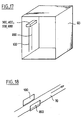
- FIG. 7 Another embodiment has been illustrated in FIG. 7 in which the reference probe 200 is formed of an electrically body conductor arranged in the tank 10, at least substantially parallel to the measurement probe 100.
- a measurement probe 100 and a measurement probe 200 (here in accordance with the variant of FIG. 7 but likely to conform to any of the other variants of the invention) associated with two electrodes 150, 250 placed near the bottom of a tank containing the fluid to be analyzed in order to be always immersed in this environment and connected to the integrating stage 550 by suitable electrically isolated connections.
- a reference probe 200 here connected to the tank 10 made of electrically conductive material, but capable of being formed of a body separate from the tank placed in it, and two probes 100, 100 'respectively located at the high level and at the level low to detect. These two measurement probes 100, 100 'are connected successively to supply means and to integrating stages respective 500 via reversing switches 420 respectively associated as described above for FIG. 1.
- a voltage variation is obtained at the output of the integrator stage 500 associated when the analyzed fluid crosses, by excess or by default, the level of the measurement probe 100 or 100 'considered. It is enough by therefore proceed by comparison between the output signal of the integrator stages 500 and a reference signal to know the crossing of high or low level in the tank.
- FIG. 10 illustrates an alternative embodiment comprising two measurement probes 100 arranged in a tank 10 respectively at a high level and at a low level to be detected and a probe reference 200 placed in the tank near the bottom thereof.
- FIG. 11 An alternative embodiment used has been illustrated in FIG. 11 preferably for the identification of the product analyzed, for example for measuring the quality of oil on a motor vehicle, or even for discrimination in the quality of food or products oil.
- a measurement probe 100 comprising a vertical rod 102 of electrically conductive material which ends at its base with a circular crown 103.
- This probe measure 100 is covered at its vertical rod 102, with a material electrically insulating 104 itself covered at the periphery of a probe reference 200. It is the same at the level of the crown 103.
- the probe reference 200 is spaced from the insulation 104 (or the measurement probe 100 is spaced from the insulation 104) by a distance d to allow the fluid analyzed to enter the space thus defined between the insulator 104 and the probe reference 200 or the measurement probe 100.
- a simple detection device as illustrated on the Figure 5 can be used not for level detection, but for discrimination or identification of the product analyzed, by direct exploitation of the signal obtained representative of the permittivity of the medium located between the two probes 100 and 200.
- FIG. 12 Another variant embodiment has been illustrated in FIG. 12. Similar to Figures 9 and 10, for level detection, in which the 100 measurement probes are located on the outside of the tank 10. This variant typically applies to the tank formed of a material electrically insulating.
- FIG. 13 Another embodiment has been illustrated in FIG. 13. with a 480 temperature sensor to provide compensation insofar.
- FIG. 13 corresponds to a measurement probe 100 and a reference probe 200 of the type illustrated in FIG. 6.
- the invention is not limited to this variant. It can apply to any other geometry and arrangement of probes according to the invention.
- the temperature probe is placed on the measurement probe 100.
- the temperature probe 480 can however be placed in any other place.
- the output signal from the temperature probe 480 illustrated on the figure 13 is used on the one hand, to correct the value of the tension -E applied to the measurement probe 100 during times T1 and on the other hand, to define a correction voltage applied to the input of the stage integrator 500 during the same time T2.
- the voltage -E is obtained at the output of an amplifier operational 481 whose non-inverting input is connected on the one hand, to the output of the temperature sensor 480 by a resistor 482 and on the other hand to a fixed reference voltage, via a resistor 483.
- the inverting input of the operational amplifier 481 is connected to the mass by a resistor 484 and at its exit by a resistor 485.
- the output of amplifier 481 is connected to the measurement probe 100 by means of the above-mentioned reversing switch 420.
- the correction voltage is taken via a reversing amplifier 486 on the adjustable point of a potentiometer 487 placed between earth and the output of amplifier 481
- the output of the inverting amplifier 486 is connected to the input of the integrator stage 500, during the time T2 via a switch 488 controlled by the time base 410.
- a circuit comprising a correction as a function of the temperature at using components 480 to 488, as shown in figure 13 can be operated in a simple application to product discrimination without level measurement.
- the feedback applied to the amplifier operational 481, via resistor 482 can come from non not a temperature sensor, but a processing stage receiving a signal from a measurement probe similar to probe 150 illustrated in Figure 8 to ensure a correction depending on the real permittivity of the detected medium.
- Generally in the context of the present invention can compensate the initial offset voltage in two ways: a) by neutralizing the initial offset by an amplifier according to the switching system of capacity 600 and by applying a counter voltage of opposite sign to the field applied to the summation point of the operational amplifier 510 or b) applying synchronously on the point of summation of the switching amplifier 600, during the charge counting, a counter voltage of opposite sign to the field applied.
- FIG. 14 illustrates an alternative embodiment for the detection or product discrimination, for example between solid, liquid products or gaseous, such as water or gas, in a non-conductive conduit 30.
- two probes respectively measure 100 and reference 200 placed on the wall of the pipe 30, for example, but not limitatively diametrically opposite.
- the 100 probes and 200 are protected from the media circulating in the conduit 30 by a waterproof coating with respect to these environments.
- a waterproof coating with respect to these environments.
- Such a device allows in particular to detect the presence of water in a gas.
- the integrator stage 500 forming a charge counting system delivers at its output a voltage proportional to the permittivity of the product located between electrodes 100 and 200
- the ratio between the permittivity of water and the permittivity of most gases being greater than 15, these means make it easy to discern the presence of water or gas in the leads.
- the measurement probe and the reference are formed of conductive bodies, for example wires electric, which run along an area to be monitored.
- the distance between the two probes 100 and 200 can be around 5cm.
- the distance between the two probes 100 and 200 can typically be understood between 1 and 10 cm, or very preferably of the order of 5 cm.
- the bodies making up the probes 100, 200 can be partially insulated or electrically shielded along their length, for areas of these probes not significant. Such local insulation or shielding can be formed by surrounding the measurement probe 100 locally with a conductive sheath 40 referenced to the potential of the reference probe 200. Any movement of a person or an object in the environment of probes 100, 200 modifies the permittivity of the medium and therefore causes variation of the voltage at the output of the integrator stage 500 and allows a intrusion detection.
- the circuit according to the invention allows for a voltage applied between the measurement probe 100 and the reference probe 200 of the order of 4 volts to detect a displacement up to 40cm from the probes.
- the environment can, over time, generate a drift or offset voltage as a function of the ambient temperature and hydrometric degree. It can be corrected using a 730 module as illustrated in figure 15 calculating the average value of this drift and correcting the signal accordingly.
- a variant of the device illustrated in FIG. 15 can be used for the protection of paintings or works of art or equivalent.
- probes 100, 200 respectively dedicated to each object to be monitored, or a pair of probes 100, 200 associated with a set of such objects to be monitored, for example in a display case or at a demonstration or exhibition place. It is enough in the latter case, make sure to give the two probes 100, 200 a sufficient length to cover the entire environment of the objects in question.
- the probes 100, 200 can be under or behind the support of the objects to watch. Again as with the other embodiments in accordance with the present invention, care should be taken to neutralize the areas of the connecting wires of these probes, not dedicated to detection, for avoid false alarms.
- the place where the objects are placed, table, display or display case must not be metallic or have electrically conductive structures connected to earth.
- Such a system can be used for example to detect the position, direction or presence of a user to ensure intelligent control of an airbag in the event of choc.
- the seat is preferably equipped with several pairs of measurement probes 100 and reference probes 200 arranged, by example under the seat cover, next to characteristic areas, for example example in the legs, back, shoulders and head.
- the outputs of these probes can be directed to processing stages or be linked to a common processing stage by through a multiplexer.
- the exploitation of the signals delivered by the probes can be subject many variations.
- a computer can summing, according to a determined weighting, the signals from each of the probes.
- Such a device makes it possible for example to distinguish a child from a adult, to order a airbag accordingly, to avoid to injure the user, during an implementation.
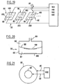
- FIG. 17 illustrates an alternative embodiment designed for detecting the passage of people or objects through a gantry 60, by example for counting or alarm purposes.
- the two measurement probes 100 and reference 200 are placed for example parallel on a wall of the gantry 60, for example a vertical side wall.
- the two probes 100, 200 can be formed of electric wires extending over the entire height of gantry 60 and separated by a distance of the order of 5 cm.
- gantry 60 does not include other structures electrically conductive, especially metallic, connected to earth.
- the same type of device can be used for the detection of passing, moving, or counting objects.
- a measurement probe 100 and a reference probe 200 arranged respectively on either side of a belt 70 ensuring the movement of the objects as illustrated in FIG. 18, or juxtaposed along this carpet.
- each of the keys 80 is formed by two pads of electrically conductive material, forming respectively a measurement probe 100 and a reference probe 200, arranged on a support 82, preferably under an electric screen screen-printed insulation, for example formed from a plastic sheet.
- the two probes 100 and 200 can for example be separated from a few mm.
- the permittivity of the environment surrounding the probes 100 and 200 varies when a user approaches the detection area corresponding materialized by these probes, which causes a variation the output level of an associated charge integrator stage.
- Respondents 100 and 200 are connected to the processing means 500 by any means 20, 22
- the connecting means thus formed must be neutralized by shielding, outside the detection zones sought, to avoid spurious detection effects when the user approaches of these connecting areas.
- the reference probes 200 are preferably all interconnected.
- Each key formed by a pair of probes 100 and 200 can be connected to a respective integrator stage 500.
- the different keys are connected to an integrator stage common via a multiplexer. In this case each of the keys is successively controlled by the aforementioned sequence T1, T2 and an evolution of the signal at the output of the integrator stage 500 is attributed to the key controlled in synchronism.
- FIG. 20 Another embodiment has been illustrated in FIG. 20. according to the present invention, forming a pressure sensor.
- the two probes 100 and 200 are placed respectively on two elements of a sensor capable of relative displacement under the effect of pressure applied.
- the sensor 84 includes a housing 85 divided into two chambers 86, 87 by a membrane flexible deformable 88 under the effect of the pressure applied in a first chamber 86 via a nozzle 89.
- One of the two probes, such as the measurement probe 100 is placed on the membrane deformable 88, and the other, such as the reference probe 200, on a wall fixed to the sensor housing, for example the bottom wall of the second room 87, or vice versa.
- the second chamber 87 can be closed or vented or communicated with a reference pressure.
- the deformable membrane 88 may or may not be associated with a spring of tared solicitation.
- Probes 100 and 200 are connected to an integrator stage 500, by any appropriate means, for example through a flexible conductor, for the probe placed on the deformable membrane.
- the integrator stage output voltage 500 associated with the sensor illustrated on the figure varies inversely proportional to the distance between probes 100 and 200 translating the pressure variations.
- FIG. 21 Another embodiment has been illustrated in FIG. 21. according to the present invention, forming a swelling state sensor of a tire 90.
- a measurement probe 100 and a probe 200 are respectively located in two areas of the tire or the structure associated therewith, capable of relative displacement according to the inflation state of the tire.
- the measurement probe 100 can be constituted by the radial metal carcass of tire 90, while the reference 200 consists of the rim or an implanted metal tape on the rim 92 and insulated therefrom by an electrically insulating material, such as than an elastomer, or vice versa.
- Probes 100 and 200 are connected by any suitable means, for example a 20/22 shielded link, on one floor integrator 500 placed on the rim.
- the distance between the two probes 100 and 200 varies depending on the state of inflation of the tire. So it is the same for the signal level obtained at the output of the integrator stage 500.
- the connection between the rim and the vehicle hub or more generally the chassis thereof, for the transmission of the corresponding information, can be operated by any suitable means, for example by a electromagnetic transponder or an optical link.
- the present invention offers many advantages over measuring devices previously proposed.
- the present invention also makes it possible to produce means of detection with perfect galvanic isolation and therefore total safety for the user.
- a perfectly electrically insulating screen for example but not limited to in the form of a touch screen.
- Such a device can for example find application in the management of utilities in a sensitive environment, for example a bathroom.
- the invention can be embodied by a zone or button panel each associated with a respective measurement probe 100, to ensure the command of a specific function, such as a command of closing / opening of tap or valve, a “flow adjustment” function, a “hot water” function, a “cold water” function, or even any other equivalent function, for example through an organ electro-mechanical adapted.
Landscapes
- Physics & Mathematics (AREA)
- General Physics & Mathematics (AREA)
- Engineering & Computer Science (AREA)
- Power Engineering (AREA)
- Electromagnetism (AREA)
- Thermal Sciences (AREA)
- Fluid Mechanics (AREA)
- Measurement Of Resistance Or Impedance (AREA)
- Investigating Or Analyzing Materials By The Use Of Electric Means (AREA)
- Measurement Of Levels Of Liquids Or Fluent Solid Materials (AREA)
- Measuring Fluid Pressure (AREA)
- Ceramic Capacitors (AREA)
- Air Bags (AREA)
- Burglar Alarm Systems (AREA)
- Measurement Of Length, Angles, Or The Like Using Electric Or Magnetic Means (AREA)
- Transmission And Conversion Of Sensor Element Output (AREA)
Description
- la figure 1 représente schématiquement la structure d'un dispositif de mesure conforme à un premier mode de réalisation de la présente invention,
- la figure 2 représente une variante d'un tel dispositif comprenant une sonde de mesure auxiliaire assurant une correction de permittivité,
- la figure 3 représente une autre variante conforme à un mode de réalisation préférentiel de la présente invention, comprenant des moyens aptes à appliquer une tension moyenne nulle sur la sonde de mesure,
- la figure 4 représente schématiquement une variante de dispositif conforme à la présente invention, adaptée pour déterminer le spectre du produit analysé,
- les figures 5 à 13 représentent diverses variantes de dispositifs conformes à la présente invention conçus pour la détection de niveau dans un réservoir,
- la figure 14 illustre une variante d'application à la détection de produit dans un conduit,
- la figure 15 illustre une variante d'application à la détection d'intrusion,
- la figure 16 illustre une variante d'application à la détection de la présence et/ou de la position d'un usager sur un siège,
- la figure 17 illustre une variante d'application à la détection de passage dans un portique,
- la figure 18 illustre une variante d'application à la détection d'objets transportés par une bande transporteuse,
- la figure 19 illustre une variante d'application pour la réalisation d'un clavier à touches,
- la figure 20 illustre une variante d'application pour la réalisation d'un capteur de pression et
- la figure 21 illustre une variante d'application pour la réalisation d'un détecteur de pression de pneumatique.
- une sonde de mesure 100,
- une sonde de référence 200,
- un moyen d'alimentation électrique 300,
- des moyens de commande 400 et
- un étage intégrateur 500.
QC520 = 0
QC530 = 0, et
QCs = 0.
- E.Cs = Vs2.C520, en appelant Vs2 la tension de sortie de l'amplificateur opérationnel 510 pendant la séquence T2.
| de préférence | 0,1 Cs < C530 < 10Cs |
| avantageusement | 0,5 Cs < C530 < 5Cs et |
| très avantageusement | Cs ≃ C530. |
- un convertisseur analogique/numérique fournissant des valeurs numériques du signal analogique issu de l'étage intégrateur 716,
- un organe de commande contrôlant des moyens de mémorisation stockant les valeurs numériques du signal, et
- des moyens de calcul, formés par exemple d'un DSP, d'un microcontrôleur ou d'un microprocesseur.
- effectuer des opérations de filtrage numérique récursif,
- calculer des transformées de Fourier et des densités spectrales en temps réel ou différé avec un nombre de points et une résolution suffisante et affinée selon des techniques classiques de fenêtrage (rectangulaire, Hamming, etc ... ) ou de recouvrement,
- calculer des spectres croisés en temps réel ou différé sur des intervalles de temps glissant,
- calculer des moyennes glissantes dans le domaine temporel et fréquentiel, et
- calculer des fonctions de corrélation et d'intercorrélation dans le domaine temporel ou fréquentiel et effectuer le cas échéant des recherches dans une base de données numériques stockant des signatures caractérisées.
- la mesure de niveau, par exemple
- sur des liquides ou des matériaux pulvérulents électriquement conducteurs ou isolants,
- sur des produits pétroliers tels que des gaz de pétrole liquéfiés (GPL),
- les détections précitées étant opérées sous forme de mesure continue de niveau ou sous forme de simples détections au niveau de repères déterminés par exemple en tant que de détecteur de niveau haut et de niveau bas, quelle que soit la nature des réservoirs impliqués, par exemple en métal ou en matière plastique,
- la discrimination analogique des produits, par exemple
- dans le domaine automobile tel que la détermination de la qualité et/ou de l'usure de l'huile,
- dans le domaine des produits pétroliers,
- dans le domaine alimentaire pour le contrôle de la qualité des produits et le dosage,
- voir dans tout autre domaine, par exemple la détection d'un type de produit dans une canalisation, par exemple la discrimination entre l'eau et le gaz dans un tuyau en matière plastique, notamment en polychlorure de vinyl (PVC),
- la détection de présence ou d'intrusion, et notamment :
- la détection d'intrusion appliquée à la protection d'objets de toute sorte,
- la détection d'intrusion appliquée en particulier à la protection des oeuvres d'art,
- la détection d'intrusion appliquée pour la protection de vitrine dans un magasin,
- la détection de présence sur un siège automobile pour l'identification de la position de l'usager pour la gestion intelligente de différents organes du véhicule automobile telle que les coussins gonflables ou airbags, la position de la colonne de direction ou hauteur de volant ou l'orientation des rétroviseurs,
- la détection de présence ou d'intrusion appliquée aux personnes (pour application à des alarmes ou au comptage),
- la détection de présence appliquée au comptage d'objets,
- la détection de présence appliquée à la réalisation d'un clavier tactile.
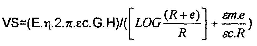
η = 0,5 = T2/(T1+T2) rapport cyclique neutralisant l'hystérésis rémanente de charges
εm = permittivité du liquide analysé
εc = permittivité du revêtement isolant de la sonde
G = gain du système
R = rayon de la sonde de mesure 100
e = épaisseur du revêtement isolant sur la sonde de mesure 100
H = hauteur du liquide conducteur ou du pulvérulent
E = valeur du champ appliqué.
Claims (47)
- Dispositif de mesure exploitant une mesure indirecte de permittivité, comprenant deux corps électriquement conducteurs constituant respectivement une sonde de mesure (100) et une sonde de référence (200), des moyens d'alimentation électrique (300) aptes à délivrer une tension électrique continue d'amplitude contrôlée, un étage intégrateur (500) comprenant un système à commutation de capacité (530) et des moyens de commande (400) adaptés pour définir cycliquement, à une fréquence contrôlée, une suite de deux séquences : une première séquence (T1) au cours de laquelle les moyens d'alimentation électrique (300) sont reliés à la sonde de mesure (100) pour appliquer un champ électrique entre la sonde de mesure (100) et la sonde de référence (200) et accumuler des charges électriques sur la sonde de mesure (100), puis une seconde séquence (T2) au cours de laquelle les moyens d'alimentation électrique (300) sont déconnectés de la sonde de mesure (100) et celle-ci est reliée à un point de sommation de l'étage intégrateur (500) pour transférer des charges dans l'étage intégrateur (500) et obtenir en sortie de celui-ci un signal représentatif de la permittivité existant entre la sonde de mesure (100) et la sonde de référence (200), l'étage intégrateur (500) comprenant un amplificateur opérationnel (510), et un condensateur d'intégration (520) monté en contre réaction sur cet amplificateur (510) caractérise par le fait que l'étage intégrateur (500) comprend un second condensateur (530) commuté entre la sortie et l'entrée de ramplificateur opérationnel (510) au rythme des séquences (T1, T2) pilotées par des moyens de commande (400), de sorte que en régime d'équilibre établi, on obtienne en sortie de l'amplificateur opérationnel (510), une tension "Vs équilibre" égale à : -Ecs/C530, relation dans laquelle -E désigne l'amplitude de la tension aux bornes des moyens d'alimentation électrique (300), et Cs et C530 désignent respectivement les valeurs des capacités définies entre la sonde de mesure (100) et la sonde de référence d'une part et le second condensateur commuté (530) d'autre part.
- Dispositif selon la revendication 1, caractérisé par le fait que le condensateur commuté (530) a une capacité du même ordre de grandeur que la capacité définie entre la sonde de mesure (100) et la sonde de référence (200).
- Dispositif selon l'une des revendications 1 ou 2, caractérisé par le fait que le condensateur d'intégration (520) est placé entre l'entrée inverseuse et la sortie de l'amplificateur opérationnel (510).
- Dispositif selon l'une des revendications 1 à 3, caractérisé par le fait que le condensateur commuté (530) est relié à la sortie de l'amplificateur opérationnel (510) pendant les séquences (T1) d'alimentation de la sonde de mesure (100) et à l'entrée de l'amplificateur opérationnel (510) pendant les séquences (T2) de liaison de la sonde de mesure (100) sur l'entrée de cet amplificateur (510).
- Dispositif selon l'une des revendications 1 à 4, caractérisé par le fait que le condensateur commuté (530) est commuté à des instants simultanés à la commutation de la sonde de mesure (100).
- Dispositif selon l'une des revendications 1 à 5, caractérisé par le fait qu'il comprend des moyens aptes à appliquer une tension moyenne nulle sur la sonde de mesure (100).
- Dispositif selon les revendications 1 et 6 prises en combinaison, caractérisé par le fait que l'amplificateur opérationnel (510) reçoit sur une seconde entrée, opposée à celle destinée à être reliée séquentiellement à la sonde de mesure. (100) une tension (+E) de signes opposés à la tension (-E) appliquée par les moyens d'alimentation sur la sonde de mesure.
- Dispositif selon la revendication 7, caractérisé par le fait que la tension (+E2) appliquée sur la seconde entrée de l'amplificateur opérationnel (510) est égale à p fois, en valeur absolue, l'amplitude de la tension d'alimentation (-E1) délivrée par les moyens d'alimentation (300) à la sonde de mesure (100).
- Dispositif selon l'une des revendications 1 à 8, caractérisé par le fait que les moyens de commande (400) sont adaptés pour définir un rapport cyclique de 50%, soit deux séquences (T1, T2) successives de même durée.
- Dispositif selon l'une des revendications 1 à 9, caractérisé par le fait que les moyens de commande (400) sont adaptés pour appliquer des échelons de tension sur la sonde de mesure (100).
- Dispositif selon l'une des revendications 1 à 10, caractérisé par le fait que les moyens de commande définissent des cycles de séquence (T1 et T2) à une fréquence comprise entre 5 et 50 kHz.
- Dispositif selon l'une des revendications 1 à 5 et 7, caractérisé par le fait que le condensateur (520) monté en contre réaction de l'amplificateur opérationnel (510) possède une capacité au moins 1000 fois égale à celle du condensateur de commutation (530).
- Dispositif selon l'une des revendications 1 à 12, caractérisé par le fait que l'étage intégrateur est relié à rentrée d'un étage de traitement (600) comprenant un moyen de réglage de zéro (610, 612, 614).
- Dispositif selon l'une des revendications 1 à 13, caractérisé par le fait que l'étage intégrateur (500) est relié à un étage de traitement (600) comprenant des moyens (606) de réglage pleine échelle.
- Dispositif selon l'une des revendications 1 à 14, caractérisé par le fait qu'il comprend en outre au moins une sonde de mesure auxiliaire (150) utilisée pour déterminer la permittivité de l'environnement des sondes de mesure et de référence (100, 200) et apporter une correction au traitement du signal.
- Dispositif selon la revendication 15, caractérisé par le fait que la sonde auxiliaire de mesure (150) est placée à proximité du fond d'un réservoir.
- Dispositif selon l'une des revendications 1 à 16, caractérisé par le fait qu'il comprend en outre une sonde de température apte à mesurer la température de l'environnement de la sonde de mesure (100) et de la sonde de référence (200).
- Dispositif selon l'une des revendications 15 à 17, caractérisé par le fait que les moyens de correction (150, 480) sont adaptés pour modifier le gain d'un étage d'asservissement (660).
- Dispositif selon l'une des revendications 1 à 17, caractérisé par le fait que les moyens de correction (150, 480) sont adaptés pour opérer une compensation sur la tension appliquée par les moyens d'alimentation (300) sur la sonde de mesure (100).
- Dispositif selon l'une des revendications 1 à 17 et 19, caractérisé par le fait que les moyens de correction (150, 480) sont adaptés pour générer une tension de correction appliquée sur l'entrée de l'étage intégrateur (500).
- Dispositif selon l'une des revendications 1 à 20, caractérisé par le fait qu'il comprend des moyens de compensation de la tension d'offset initiale de l'étage intégrateur (500).
- Dispositif selon la revendication 21, caractérisé par le fait que les moyens de compensation de la tension d'offset comprennent un amplificateur disposé en aval du système à commutation de capacité (600) adapté pour appliquer une contre tension de signes opposés au champ appliqué sur le point de sommation de l'étage intégrateur (500).
- Dispositif selon la revendication 21, caractérisé par le fait que les moyens de compensation d'offset comprennent des moyens aptes à appliquer de manière synchrone sur le point de sommation de l'amplificateur à commutation de capacité (600), pendant le comptage des charges, une contre tension de signes opposés au champ appliqué.
- Dispositif selon l'une des revendications 1 à 23, caractérisé par le fait qu'il comprend en outre des moyens aptes à générer un signal représentant le spectre du milieu environnant la sonde de mesure (100).
- Dispositif selon la revendication 24, caractérisé par le fait que les moyens d'analyse de spectre comprennent des moyens de calcul de transformer de Fourier et des moyens de comparaison des spectres obtenus avec des spectres numériques stockés dans une base de données.
- Dispositif selon l'une des revendications 24 ou 25, caractérisé par le fait que les moyens d'analyse de spectres comprennent un étage de mise en forme (710), un étage passe haut (712) à grand gain, un détecteur synchrone (714), un intégrateur (716) et un étage de calcul (720).
- Dispositif selon l'une des revendications 1 à 26, caractérisé par le fait qu'il comprend deux corps électriquement conducteurs (100, 200) formant respectivement sonde de mesure et sonde de référence situées à des distances comprises entre 1 et 10cm, préférentiellement de l'ordre de 5cm.
- Dispositif selon l'une des revendications 1 à 27, caractérisé par le fait que l'une au moins des sondes de mesure (100) ou de référence (200) est munie d'un revêtement électriquement isolant et étanche à l'égard du milieu environnant la sonde.
- Dispositif selon l'une des revendications 1 à 28, caractérisé par le fait que certains tronçons au moins des moyens de liaison (20, 22) raccordant la sonde de mesure (100) sont neutralisés par une gaine en matériau électriquement conducteur placé au même potentiel que la sonde de référence (200).
- Dispositif selon l'une des revendications 1 à 29, caractérisé par le fait qu'il est adapté pour opérer une fonction choisie dans le groupe comprenant une mesure de niveau, une discrimination entre produits ou une détection de présence ou d'intrusion.
- Dispositif selon l'une des revendications 1 à 30, caractérisé par le fait qu'il comprend plusieurs sondes de mesure (100) reliées à des étages intégrateurs respectifs (500).
- Dispositif selon l'une des revendications 1 à 30, caractérisé par le fait qu'il comprend plusieurs sondes de mesure (100) reliées à un étage intégrateur (500) commun par l'intermédiaire d'un multiplexeur.
- Dispositif selon l'une des revendications 1 à 32, caractérisé par le fait qu'il constitue un dispositif de mesure de niveau.
- Dispositif selon la revendication 33, caractérisé par le fait que la sonde de mesure (100) est située dans une direction générale verticale dans un réservoir (10) et par le fait que l'étage intégrateur (500) est relié à des moyens de traitement (600) adaptée pour générer un signal représentatif du niveau de fluide dans le réservoir (10).
- Dispositif selon la revendication 33, caractérisé par le fait que la sonde de mesure (100) est formée par une plage électriquement conductrice disposée dans un réservoir (10) à une hauteur correspondant à un niveau de scrutation.
- Dispositif selon l'une des revendications 33 et 35, caractérisé par le fait qu'il comprend plusieurs sondes de mesure (100) disposées à des niveaux de discrimination respectifs dans un réservoir (10).
- Dispositif selon l'une des revendications 33 à 36, caractérisé par le fait que le fluide a détecté est électriquement conducteur et que l'une au moins de la sonde de mesure (100) ou de la sonde de référence (200) est munie d'un revêtement électriquement isolant.
- Dispositif selon l'une des revendications 1 à 37, caractérisé par le fait que la sonde de référence (200) est formée par le réservoir.
- Dispositif selon rune des revendications 1 à 37, caractérisé par le fait que la sonde de référence (200) est formée d'un élément ajouré qui entoure la sonde de mesure (100).
- Dispositif selon l'une des revendications 1 à 33, caractérisé par le fait qu'il constitue un dispositif de discrimination du produit circulant dans une canalisation (30) équipé d'une sonde de mesure (100) et d'une sonde de référence (200).
- Dispositif selon l'une des revendications 1 à 33, caractérisé par le fait qu'il comprend une sonde de mesure (100) et une sonde de référence (200) qui chemine le long d'une zone à surveiller pour former dispositif détecteur d'intrusion;
- Dispositif selon l'une des revendications 1 à 33, caractérisé par le fait qu'il comprend plusieurs paires d'électrodes de mesure (100) et d'électrodes de référence (200) réparties sur un siège pour permettre la détection de la présence et/ou de la position d'un usager.
- Dispositif selon l'une des revendications 1 à 33, caractérisé par le fait qu'il comprend une sonde de mesure (100) et une sonde de référence (200) le long d'une paroi d'un portique (60) pour former détecteur de passage.
- Dispositif selon l'une des revendications 1 à 33, caractérisé par le fait qu'il comprend une sonde de mesure (100) et une sonde de référence (200) placées sur le côté d'une bande transporteuse pour la détection de passage d'objets.
- Dispositif selon l'une des revendications 1 à 33, caractérisé par le fait qu'il comprend plusieurs paires de sondes de mesure (100) et de sondes de référence (200) pour la réalisation d'un clavier à touches tactiles.
- Dispositif selon l'une des revendications 1 à 33, caractérisé par le fait que l'une des souches de mesure (100) ou de référence (200) est placée sur un élément déformable (88) pour former un capteur de pression.
- Dispositif selon l'une des revendications 1 à 33, caractérisé par le fait que la sonde de mesure (100) et la sonde de référence (200) sont placées sur deux zones d'un pneumatique susceptible de déplacement relatif en fonction de l'état de gonflement de celui-ci, pour former un capteur de gonflement de pneumatique.
Applications Claiming Priority (3)
| Application Number | Priority Date | Filing Date | Title |
|---|---|---|---|
| FR9813329A FR2785046B1 (fr) | 1998-10-23 | 1998-10-23 | Dispositif de mesure reposant sur la mesure indirecte de la permittivite |
| FR9813329 | 1998-10-23 | ||
| PCT/FR1999/002561 WO2000025098A2 (fr) | 1998-10-23 | 1999-10-21 | Dispositif de mesure capacitif |
Publications (2)
| Publication Number | Publication Date |
|---|---|
| EP1123489A2 EP1123489A2 (fr) | 2001-08-16 |
| EP1123489B1 true EP1123489B1 (fr) | 2004-07-21 |
Family
ID=9531929
Family Applications (1)
| Application Number | Title | Priority Date | Filing Date |
|---|---|---|---|
| EP99949088A Expired - Lifetime EP1123489B1 (fr) | 1998-10-23 | 1999-10-21 | Dispositif de mesure capacitif |
Country Status (13)
| Country | Link |
|---|---|
| US (1) | US6545603B1 (fr) |
| EP (1) | EP1123489B1 (fr) |
| JP (1) | JP2002528711A (fr) |
| KR (1) | KR100605285B1 (fr) |
| CN (1) | CN1210546C (fr) |
| AT (1) | ATE271688T1 (fr) |
| AU (1) | AU755548B2 (fr) |
| BR (1) | BR9914759A (fr) |
| CA (1) | CA2347988A1 (fr) |
| DE (1) | DE69918850T2 (fr) |
| FR (1) | FR2785046B1 (fr) |
| RU (1) | RU2220404C2 (fr) |
| WO (1) | WO2000025098A2 (fr) |
Families Citing this family (51)
| Publication number | Priority date | Publication date | Assignee | Title |
|---|---|---|---|---|
| LU90629B1 (de) * | 2000-08-10 | 2006-02-21 | Luxembourg Patent Co | Vorrichtung zum Feststellen eines Gasverlustes auseinem Kohlendioxid-Druckbeh{lter. |
| FR2813054B1 (fr) | 2000-08-21 | 2002-11-15 | Faure Bertrand Equipements Sa | Systeme pour vehicule, comportant un dispositif de commande adapte pour faire fonctionner un actionneur selectivement en fonction d'une valeur mesuree par un dispositif de mesure dispose dans un siege |
| FR2817035B1 (fr) * | 2000-11-23 | 2003-03-28 | Hitachi Comp Products Europ Sa | Dispositif de mesure exploitant une mesure indirecte de permittivite a sondes mulitiples |
| AU2002220801A1 (en) * | 2000-11-23 | 2002-06-03 | Hitachi Computer Products (Europe) S.A. | Capacitive measurement device |
| FR2817034B1 (fr) * | 2000-11-23 | 2003-03-28 | Hitachi Comp Products Europ Sa | Dispositif de mesure exploitant une mesure indirecte de permettivite a reponse rapide |
| FR2817036B1 (fr) * | 2000-11-23 | 2003-03-28 | Hitachi Comp Products Europ Sa | Dispositif de mesure exploitant une mesure indirecte de permettivite a grande dynamique |
| FR2817033B1 (fr) * | 2000-11-23 | 2003-03-28 | Hitachi Comp Products Europ Sa | Disposistif de mesure exploitant une mesure indirecte de permettivite comprenant des moyens de compensation en derive |
| FR2817032B1 (fr) * | 2000-11-23 | 2003-03-28 | Hitachi Comp Products Europ Sa | Perfectionnements aux dispositifs de mesure exploitant une mesure indirecte de permittivite |
| FR2826723B1 (fr) * | 2001-06-28 | 2004-01-30 | Hitachi Comp Products Europ Sa | Systeme de mesure capacitif |
| DE10207425A1 (de) * | 2002-02-21 | 2003-09-04 | Bosch Gmbh Robert | Verfahren und Meßgerät zur Ortung eingeschlossener Objekte |
| DE10309769B4 (de) * | 2002-03-08 | 2017-10-05 | Ust Umweltsensortechnik Gmbh | Anordnung zur Bestimmung von Zustandsgrößen für Flüssigkeiten in einem geschlossenen nichtmetallischen Behälter |
| FR2841841B1 (fr) | 2002-07-03 | 2004-09-10 | Faurecia Sieges Automobile | Dispositif et procede de chauffe de sieges de vehicule automobile |
| DE10231946A1 (de) * | 2002-07-15 | 2004-01-29 | Exess Engineering Gmbh | Verfahren zur Messung des Füllstandes eines Fluids in einem Behälter und entsprechender Füllstandssensor |
| FR2849918B1 (fr) * | 2003-01-10 | 2005-06-17 | Faurecia Sieges Automobile | Systeme de detection capacitif, notamment pour interieur de vehicule automobile. |
| DE10345708A1 (de) * | 2003-10-01 | 2005-04-21 | Volkswagen Ag | Füllstand-Messsystem |
| DE102004019351A1 (de) * | 2003-12-22 | 2005-07-14 | BSH Bosch und Siemens Hausgeräte GmbH | Geschirrspülmaschine mit einem System zur Füllstandserkennung |
| FR2871118B1 (fr) | 2004-06-07 | 2006-09-01 | Faurecia Sieges Automobile | Systeme et procede de caracterisation de l'occupation d'un element de siege de vehicule, et element de siege pour un tel systeme |
| JP2006180935A (ja) * | 2004-12-24 | 2006-07-13 | Olympus Corp | 医療機器装置 |
| US8698509B2 (en) * | 2005-04-27 | 2014-04-15 | Roho, Inc. | Proximity sensor |
| FR2889304B1 (fr) * | 2005-07-28 | 2007-09-21 | Hitachi Comp Products Europ Sa | Capteur capacitif permettant une discrimination morphologique d'un occupant dans un siege automobile |
| US7388509B2 (en) * | 2005-09-28 | 2008-06-17 | International Lubricants, Inc. | System and method for detecting electrolysis in an automobile system |
| FR2892509B1 (fr) * | 2005-10-26 | 2007-12-21 | Inergy Automotive Systems Res | Jauge capacitive pour reservoir a carburant |
| US20070252715A1 (en) * | 2006-04-27 | 2007-11-01 | Honeywell International Inc. | Liquid quality and level sensor |
| EP1857330B1 (fr) | 2006-05-17 | 2009-11-25 | Hitachi Computer Products (Europe) S.A.S. | Procédé pour déterminer la morphologie d'un occupant dans un siège de véhicule à l'aide d'un capteur capacitif |
| EP1857329A1 (fr) * | 2006-05-17 | 2007-11-21 | Hitachi Computer Products (Europe) S.A.S. | Procédé pour améliorer la localisation d'un objet en regard d'un capteur |
| JP2008060877A (ja) | 2006-08-31 | 2008-03-13 | Hitachi Ltd | Mimo無線データ伝送システム |
| US8636670B2 (en) | 2008-05-13 | 2014-01-28 | The Invention Science Fund I, Llc | Circulatory monitoring systems and methods |
| US20090287120A1 (en) | 2007-12-18 | 2009-11-19 | Searete Llc, A Limited Liability Corporation Of The State Of Delaware | Circulatory monitoring systems and methods |
| US9717896B2 (en) | 2007-12-18 | 2017-08-01 | Gearbox, Llc | Treatment indications informed by a priori implant information |
| US8154315B2 (en) * | 2008-04-08 | 2012-04-10 | Formfactor, Inc. | Self-referencing voltage regulator |
| JP5276921B2 (ja) * | 2008-08-08 | 2013-08-28 | 株式会社日立ハイテクノロジーズ | 検査装置 |
| DE202009018553U1 (de) | 2009-11-11 | 2012-02-29 | Ident Technology Ag | Sensorelektronik für eine Mehrzahl von Sensorelementen |
| DE102009052537B4 (de) * | 2009-11-11 | 2011-12-22 | Ident Technology Ag | Sensorelektronik für eine Mehrzahl von Sensorelementen sowie Verfahren zum Bestimmen einer Position eines Objektes an den Sensorelementen |
| GB201011785D0 (en) | 2010-07-13 | 2010-08-25 | Oxford Rf Sensors Ltd | Permittivity sensor |
| CN101976147B (zh) * | 2010-09-30 | 2013-03-27 | 江苏惠通集团有限责任公司 | 触摸识别方法、触摸键结构及触摸装置 |
| DE102011079174A1 (de) * | 2011-07-14 | 2013-01-17 | Zf Friedrichshafen Ag | Positionserfassungsvorrichtung |
| DE102011053407A1 (de) | 2011-09-08 | 2013-03-14 | Beko Technologies Gmbh | Füllstandsüberwachung |
| CN103164875B (zh) * | 2011-12-08 | 2016-03-30 | 北京北大千方科技有限公司 | 车载设备 |
| US9810567B2 (en) * | 2013-05-03 | 2017-11-07 | Dickey-John Corporation | Calibration-free continuous bin level sensor |
| RU2559697C2 (ru) * | 2013-05-29 | 2015-08-10 | Шепеленко Виталий Борисович | Устройство индикации вмешательства |
| RU2559700C2 (ru) * | 2013-05-29 | 2015-08-10 | Шепеленко Виталий Борисович | Способ контроля доступа к объекту и устройство для его реализации |
| RU2559696C2 (ru) * | 2013-05-29 | 2015-08-10 | Шепеленко Виталий Борисович | Электронный индикатор и способ его применения |
| RU2559695C2 (ru) * | 2013-05-29 | 2015-08-10 | Шепеленко Виталий Борисович | Электронный индикатор |
| AU2014380163B2 (en) | 2014-01-29 | 2018-10-04 | Roho, Inc. | Cushion immersion sensor |
| CH709917A2 (de) * | 2014-07-24 | 2016-01-29 | Tecan Trading Ag | Verfahren und Vorrichtung zum Unterscheiden zwischen einer Schaum- und/oder Flüssigkeitskontaktierung. |
| US9976893B2 (en) * | 2015-09-16 | 2018-05-22 | Finetek Co., Ltd. | Method for measuring permittivity of material |
| RU2671299C9 (ru) * | 2017-04-12 | 2018-12-24 | Акционерное общество "Концерн "Созвездие" | Способ измерения параметров подстилающей среды и устройство для его осуществления |
| US10845263B2 (en) * | 2018-04-17 | 2020-11-24 | Mks Instruments, Inc. | Thermal conductivity gauge |
| CN113252734B (zh) * | 2021-06-22 | 2021-09-24 | 电子科技大学 | 一种电阻型气体传感器柔性电路及气体浓度计算方法 |
| CN115389823B (zh) * | 2022-08-26 | 2025-03-07 | 北京空间机电研究所 | 一种探测器光电二极管节点电容测试装置和方法 |
| KR102749450B1 (ko) * | 2023-04-17 | 2024-12-31 | 한라아이엠에스 주식회사 | 정전용량식 레벨 측정장치 |
Family Cites Families (11)
| Publication number | Priority date | Publication date | Assignee | Title |
|---|---|---|---|---|
| US3580074A (en) * | 1969-05-23 | 1971-05-25 | Trans Sonics Inc | Temperature-compensated liquid quantity gage |
| US3811051A (en) * | 1972-11-03 | 1974-05-14 | Robertshaw Controls Co | Capacitance responsive detector system |
| US4485673A (en) * | 1981-05-13 | 1984-12-04 | Drexelbrook Engineering Company | Two-wire level measuring instrument |
| DE3413849C2 (de) * | 1984-02-21 | 1986-07-10 | Dietrich 8891 Obergriesbach Lüderitz | Kapazitäts-Meßgerät |
| US5050431A (en) * | 1990-09-12 | 1991-09-24 | Robertshaw Controls Company | Liquid level sensing device and methods of making an operating the same |
| RU2042929C1 (ru) * | 1993-02-01 | 1995-08-27 | Ковровский электромеханический завод | Емкостный измеритель уровня |
| DE4312432A1 (de) * | 1993-04-17 | 1994-10-20 | Deutsche Aerospace | Verfahren zur Messung von Flüssigkeitspegeln, Flüssigkeitsständen und Durchflußraten bei niederkonzentrierten Elektrolyten |
| US5461321A (en) * | 1993-09-17 | 1995-10-24 | Penberthy, Inc. | Apparatus and method for measuring capacitance from the duration of a charge-discharge charge cycle |
| US5406843A (en) * | 1993-10-27 | 1995-04-18 | Kdi Corporation, Inc. | Digital liquid level sensing apparatus |
| DE4434338C2 (de) * | 1994-09-26 | 1996-12-19 | Siemens Ag | Ausleseschaltung für einen kapazitiven Sensor |
| DE19513022C1 (de) * | 1995-04-06 | 1996-08-14 | Siemens Ag | Schaltungsanordnung und Verfahren zur Bestimmung von Kapazitätsdifferenzen |
-
1998
- 1998-10-23 FR FR9813329A patent/FR2785046B1/fr not_active Expired - Fee Related
-
1999
- 1999-10-21 JP JP2000578625A patent/JP2002528711A/ja active Pending
- 1999-10-21 CN CNB998135240A patent/CN1210546C/zh not_active Expired - Fee Related
- 1999-10-21 KR KR1020017005065A patent/KR100605285B1/ko not_active Expired - Fee Related
- 1999-10-21 WO PCT/FR1999/002561 patent/WO2000025098A2/fr not_active Ceased
- 1999-10-21 CA CA002347988A patent/CA2347988A1/fr not_active Abandoned
- 1999-10-21 EP EP99949088A patent/EP1123489B1/fr not_active Expired - Lifetime
- 1999-10-21 AT AT99949088T patent/ATE271688T1/de not_active IP Right Cessation
- 1999-10-21 US US09/830,318 patent/US6545603B1/en not_active Expired - Fee Related
- 1999-10-21 DE DE69918850T patent/DE69918850T2/de not_active Expired - Fee Related
- 1999-10-21 RU RU2001113742/28A patent/RU2220404C2/ru not_active IP Right Cessation
- 1999-10-21 AU AU62093/99A patent/AU755548B2/en not_active Ceased
- 1999-10-21 BR BR9914759-9A patent/BR9914759A/pt not_active IP Right Cessation
Also Published As
| Publication number | Publication date |
|---|---|
| DE69918850D1 (de) | 2004-08-26 |
| WO2000025098A2 (fr) | 2000-05-04 |
| WO2000025098A3 (fr) | 2000-10-12 |
| RU2220404C2 (ru) | 2003-12-27 |
| EP1123489A2 (fr) | 2001-08-16 |
| AU755548B2 (en) | 2002-12-12 |
| CA2347988A1 (fr) | 2000-05-04 |
| KR20010099739A (ko) | 2001-11-09 |
| CN1326544A (zh) | 2001-12-12 |
| FR2785046B1 (fr) | 2001-01-26 |
| AU6209399A (en) | 2000-05-15 |
| JP2002528711A (ja) | 2002-09-03 |
| FR2785046A1 (fr) | 2000-04-28 |
| CN1210546C (zh) | 2005-07-13 |
| DE69918850T2 (de) | 2005-08-11 |
| BR9914759A (pt) | 2001-07-10 |
| KR100605285B1 (ko) | 2006-07-28 |
| ATE271688T1 (de) | 2004-08-15 |
| US6545603B1 (en) | 2003-04-08 |
Similar Documents
| Publication | Publication Date | Title |
|---|---|---|
| EP1123489B1 (fr) | Dispositif de mesure capacitif | |
| EP1831652B1 (fr) | Capteur capacitif de niveau d'un liquide et methode d'estimation du niveau | |
| EP3814196B1 (fr) | Dispositif capacitif de détection de la présence d'une personne à proximité ou au contact d'un composant d'un véhicule automobile | |
| RU2001113742A (ru) | Измерительное устройство для косвенного измерения диэлектрической проницаемости | |
| WO2015028508A1 (fr) | Detection d'arcs electriques dans les installations photovoltaïques | |
| WO1999049298A1 (fr) | Procede d'etalonnage en longueur d'onde d'un dispositif de filtrage d'un rayonnement electromagnetique | |
| FR2577059A1 (fr) | Detecteur de flammes | |
| FR2985017A1 (fr) | Dispositif de mesure d'une variation d'une capacite a faible consommation et procede associe | |
| EP2638457A1 (fr) | Procede de detection d'objet d'interet dans un environnement perturbe, et dispositif d'interface gestuel mettant en oeuvre ce procede | |
| FR3006793A1 (fr) | Dispositif, capteur et procede de detection de la presence d'un utilisateur pour l'ouverture d'un acces a un vehicule automobile | |
| FR3063097A1 (fr) | Procede de determination de contacts parasites sur un capteur de detection d'approche et/ou de contact et dispositif de determination associe | |
| EP3384592A1 (fr) | Procede et dispositif de detection d'un arc electrique dans une installation photovoltaïque | |
| WO1994001790A1 (fr) | Detection d'une perturbation electrique ou ionique | |
| FR2872714A1 (fr) | Jouet sensible au toucher humain | |
| Steiner et al. | Polymer coated capacitive microintegrated gas sensor | |
| Dutta et al. | Direct interfacing circuit‐based e‐nose for gas classification and its uncertainty estimation | |
| EP1336082B1 (fr) | Dispositif de mesure capacitif | |
| WO2023126303A1 (fr) | Dispositif de caractérisation d'un milieu par spectroscopie capacitive | |
| FR2817036A1 (fr) | Dispositif de mesure exploitant une mesure indirecte de permettivite a grande dynamique | |
| FR2512860A1 (fr) | Dispositif de commande de surface de type numerique pour essais de sols et de roches in situ avec sonde profonde | |
| FR2744547A1 (fr) | Procede et systeme de detection de la presence et d'identification d'objets ou de personnes dans un volume donne, notamment le passager dans un vehicule automobile | |
| FR2817032A1 (fr) | Perfectionnements aux dispositifs de mesure exploitant une mesure indirecte de permittivite | |
| Wagner et al. | Simultaneous measurement of time‐of‐wetness and electrolyte concentrations with IDE sensors by evaluation of impedance spectra using an artificial neural network | |
| MARCHETTI et al. | Development of an impedentiometric electronic tongue | |
| WO2000063682A2 (fr) | Procede et appareil capteur permettant de detecter et d'identifier des fluides |
Legal Events
| Date | Code | Title | Description |
|---|---|---|---|
| PUAI | Public reference made under article 153(3) epc to a published international application that has entered the european phase |
Free format text: ORIGINAL CODE: 0009012 |
|
| 17P | Request for examination filed |
Effective date: 20010518 |
|
| AK | Designated contracting states |
Kind code of ref document: A2 Designated state(s): AT BE CH CY DE DK ES FI FR GB GR IE IT LI LU MC NL PT SE |
|
| AX | Request for extension of the european patent |
Free format text: AL;LT;LV;MK;RO;SI |
|
| GRAP | Despatch of communication of intention to grant a patent |
Free format text: ORIGINAL CODE: EPIDOSNIGR1 |
|
| GRAS | Grant fee paid |
Free format text: ORIGINAL CODE: EPIDOSNIGR3 |
|
| GRAA | (expected) grant |
Free format text: ORIGINAL CODE: 0009210 |
|
| AK | Designated contracting states |
Kind code of ref document: B1 Designated state(s): AT BE CH CY DE DK ES FI FR GB GR IE IT LI LU MC NL PT SE |
|
| PG25 | Lapsed in a contracting state [announced via postgrant information from national office to epo] |
Ref country code: NL Free format text: LAPSE BECAUSE OF FAILURE TO SUBMIT A TRANSLATION OF THE DESCRIPTION OR TO PAY THE FEE WITHIN THE PRESCRIBED TIME-LIMIT Effective date: 20040721 Ref country code: IT Free format text: LAPSE BECAUSE OF FAILURE TO SUBMIT A TRANSLATION OF THE DESCRIPTION OR TO PAY THE FEE WITHIN THE PRESCRIBED TIME-LIMIT;WARNING: LAPSES OF ITALIAN PATENTS WITH EFFECTIVE DATE BEFORE 2007 MAY HAVE OCCURRED AT ANY TIME BEFORE 2007. THE CORRECT EFFECTIVE DATE MAY BE DIFFERENT FROM THE ONE RECORDED. Effective date: 20040721 Ref country code: IE Free format text: LAPSE BECAUSE OF FAILURE TO SUBMIT A TRANSLATION OF THE DESCRIPTION OR TO PAY THE FEE WITHIN THE PRESCRIBED TIME-LIMIT Effective date: 20040721 Ref country code: GB Free format text: LAPSE BECAUSE OF FAILURE TO SUBMIT A TRANSLATION OF THE DESCRIPTION OR TO PAY THE FEE WITHIN THE PRESCRIBED TIME-LIMIT Effective date: 20040721 Ref country code: FI Free format text: LAPSE BECAUSE OF FAILURE TO SUBMIT A TRANSLATION OF THE DESCRIPTION OR TO PAY THE FEE WITHIN THE PRESCRIBED TIME-LIMIT Effective date: 20040721 Ref country code: CY Free format text: LAPSE BECAUSE OF FAILURE TO SUBMIT A TRANSLATION OF THE DESCRIPTION OR TO PAY THE FEE WITHIN THE PRESCRIBED TIME-LIMIT Effective date: 20040721 Ref country code: AT Free format text: LAPSE BECAUSE OF FAILURE TO SUBMIT A TRANSLATION OF THE DESCRIPTION OR TO PAY THE FEE WITHIN THE PRESCRIBED TIME-LIMIT Effective date: 20040721 |
|
| REG | Reference to a national code |
Ref country code: GB Ref legal event code: FG4D Free format text: NOT ENGLISH |
|
| REG | Reference to a national code |
Ref country code: CH Ref legal event code: EP |
|
| REG | Reference to a national code |
Ref country code: IE Ref legal event code: FG4D Free format text: FRENCH |
|
| REF | Corresponds to: |
Ref document number: 69918850 Country of ref document: DE Date of ref document: 20040826 Kind code of ref document: P |
|
| PG25 | Lapsed in a contracting state [announced via postgrant information from national office to epo] |
Ref country code: SE Free format text: LAPSE BECAUSE OF FAILURE TO SUBMIT A TRANSLATION OF THE DESCRIPTION OR TO PAY THE FEE WITHIN THE PRESCRIBED TIME-LIMIT Effective date: 20041021 Ref country code: LU Free format text: LAPSE BECAUSE OF NON-PAYMENT OF DUE FEES Effective date: 20041021 Ref country code: GR Free format text: LAPSE BECAUSE OF FAILURE TO SUBMIT A TRANSLATION OF THE DESCRIPTION OR TO PAY THE FEE WITHIN THE PRESCRIBED TIME-LIMIT Effective date: 20041021 Ref country code: DK Free format text: LAPSE BECAUSE OF FAILURE TO SUBMIT A TRANSLATION OF THE DESCRIPTION OR TO PAY THE FEE WITHIN THE PRESCRIBED TIME-LIMIT Effective date: 20041021 |
|
| PG25 | Lapsed in a contracting state [announced via postgrant information from national office to epo] |
Ref country code: MC Free format text: LAPSE BECAUSE OF NON-PAYMENT OF DUE FEES Effective date: 20041031 Ref country code: LI Free format text: LAPSE BECAUSE OF NON-PAYMENT OF DUE FEES Effective date: 20041031 Ref country code: CH Free format text: LAPSE BECAUSE OF NON-PAYMENT OF DUE FEES Effective date: 20041031 Ref country code: BE Free format text: LAPSE BECAUSE OF NON-PAYMENT OF DUE FEES Effective date: 20041031 |
|
| PG25 | Lapsed in a contracting state [announced via postgrant information from national office to epo] |
Ref country code: ES Free format text: LAPSE BECAUSE OF FAILURE TO SUBMIT A TRANSLATION OF THE DESCRIPTION OR TO PAY THE FEE WITHIN THE PRESCRIBED TIME-LIMIT Effective date: 20041101 |
|
| LTIE | Lt: invalidation of european patent or patent extension |
Effective date: 20040721 |
|
| NLV1 | Nl: lapsed or annulled due to failure to fulfill the requirements of art. 29p and 29m of the patents act | ||
| GBV | Gb: ep patent (uk) treated as always having been void in accordance with gb section 77(7)/1977 [no translation filed] |
Effective date: 20040721 |
|
| REG | Reference to a national code |
Ref country code: IE Ref legal event code: FD4D |
|
| BERE | Be: lapsed |
Owner name: PANCIROLI, WILLIAM Effective date: 20041031 Owner name: JORDANA, PASCAL Effective date: 20041031 Owner name: LE RESTE, DANIEL Effective date: 20041031 Owner name: LAUNAY, CLAUDE Effective date: 20041031 |
|
| PLBE | No opposition filed within time limit |
Free format text: ORIGINAL CODE: 0009261 |
|
| STAA | Information on the status of an ep patent application or granted ep patent |
Free format text: STATUS: NO OPPOSITION FILED WITHIN TIME LIMIT |
|
| REG | Reference to a national code |
Ref country code: CH Ref legal event code: PL |
|
| 26N | No opposition filed |
Effective date: 20050422 |
|
| BERE | Be: lapsed |
Owner name: *PANCIROLI WILLIAM Effective date: 20041031 Owner name: *JORDANA PASCAL Effective date: 20041031 Owner name: *LE RESTE DANIEL Effective date: 20041031 Owner name: *LAUNAY CLAUDE Effective date: 20041031 |
|
| PG25 | Lapsed in a contracting state [announced via postgrant information from national office to epo] |
Ref country code: PT Free format text: LAPSE BECAUSE OF NON-PAYMENT OF DUE FEES Effective date: 20041221 |
|
| PGFP | Annual fee paid to national office [announced via postgrant information from national office to epo] |
Ref country code: FR Payment date: 20090430 Year of fee payment: 10 Ref country code: DE Payment date: 20090430 Year of fee payment: 10 |
|
| REG | Reference to a national code |
Ref country code: FR Ref legal event code: ST Effective date: 20100630 |
|
| PG25 | Lapsed in a contracting state [announced via postgrant information from national office to epo] |
Ref country code: FR Free format text: LAPSE BECAUSE OF NON-PAYMENT OF DUE FEES Effective date: 20091102 Ref country code: DE Free format text: LAPSE BECAUSE OF NON-PAYMENT OF DUE FEES Effective date: 20100501 |