EP1123494B1 - Vorrichtung zur abschottung oder prüfung eines rohrabschnitts - Google Patents
Vorrichtung zur abschottung oder prüfung eines rohrabschnitts Download PDFInfo
- Publication number
- EP1123494B1 EP1123494B1 EP99944195A EP99944195A EP1123494B1 EP 1123494 B1 EP1123494 B1 EP 1123494B1 EP 99944195 A EP99944195 A EP 99944195A EP 99944195 A EP99944195 A EP 99944195A EP 1123494 B1 EP1123494 B1 EP 1123494B1
- Authority
- EP
- European Patent Office
- Prior art keywords
- annular
- shaft
- bosses
- pipe
- fluid
- Prior art date
- Legal status (The legal status is an assumption and is not a legal conclusion. Google has not performed a legal analysis and makes no representation as to the accuracy of the status listed.)
- Expired - Lifetime
Links
Images


Classifications
-
- G—PHYSICS
- G01—MEASURING; TESTING
- G01M—TESTING STATIC OR DYNAMIC BALANCE OF MACHINES OR STRUCTURES; TESTING OF STRUCTURES OR APPARATUS, NOT OTHERWISE PROVIDED FOR
- G01M3/00—Investigating fluid-tightness of structures
- G01M3/02—Investigating fluid-tightness of structures by using fluid or vacuum
- G01M3/04—Investigating fluid-tightness of structures by using fluid or vacuum by detecting the presence of fluid at the leakage point
- G01M3/06—Investigating fluid-tightness of structures by using fluid or vacuum by detecting the presence of fluid at the leakage point by observing bubbles in a liquid pool
- G01M3/08—Investigating fluid-tightness of structures by using fluid or vacuum by detecting the presence of fluid at the leakage point by observing bubbles in a liquid pool for pipes, cables or tubes; for pipe joints or seals; for valves; for welds
-
- G—PHYSICS
- G01—MEASURING; TESTING
- G01M—TESTING STATIC OR DYNAMIC BALANCE OF MACHINES OR STRUCTURES; TESTING OF STRUCTURES OR APPARATUS, NOT OTHERWISE PROVIDED FOR
- G01M3/00—Investigating fluid-tightness of structures
- G01M3/02—Investigating fluid-tightness of structures by using fluid or vacuum
- G01M3/04—Investigating fluid-tightness of structures by using fluid or vacuum by detecting the presence of fluid at the leakage point
-
- G—PHYSICS
- G01—MEASURING; TESTING
- G01M—TESTING STATIC OR DYNAMIC BALANCE OF MACHINES OR STRUCTURES; TESTING OF STRUCTURES OR APPARATUS, NOT OTHERWISE PROVIDED FOR
- G01M3/00—Investigating fluid-tightness of structures
- G01M3/02—Investigating fluid-tightness of structures by using fluid or vacuum
- G01M3/022—Test plugs for closing off the end of a pipe
-
- G—PHYSICS
- G01—MEASURING; TESTING
- G01M—TESTING STATIC OR DYNAMIC BALANCE OF MACHINES OR STRUCTURES; TESTING OF STRUCTURES OR APPARATUS, NOT OTHERWISE PROVIDED FOR
- G01M3/00—Investigating fluid-tightness of structures
- G01M3/02—Investigating fluid-tightness of structures by using fluid or vacuum
- G01M3/26—Investigating fluid-tightness of structures by using fluid or vacuum by measuring rate of loss or gain of fluid, e.g. by pressure-responsive devices, by flow detectors
- G01M3/28—Investigating fluid-tightness of structures by using fluid or vacuum by measuring rate of loss or gain of fluid, e.g. by pressure-responsive devices, by flow detectors for pipes, cables or tubes; for pipe joints or seals; for valves ; for welds
- G01M3/2853—Investigating fluid-tightness of structures by using fluid or vacuum by measuring rate of loss or gain of fluid, e.g. by pressure-responsive devices, by flow detectors for pipes, cables or tubes; for pipe joints or seals; for valves ; for welds for pipe joints or seals
Definitions
- conduits or pipes In the fabrication of fluid flow systems, whether they be for the purposes of conveying liquid such as petrochemicals, or gases such as natural gas, or even fluidized cereals as is common in the cereal processing industry, the use of conduits or pipes is common and replete. From a fabrication point of view, pipes can only be manufactured to a finite length and therefore, various lengths or elbows must be connected together in order to structure the conduit fluid conveyance means. This is accomplished by welding butt ends of pipes together or to elbows etc., or alternatively, to weld the end of a pipe to a butt flange and to juxtapose two butt flanges together by means commonly known, for example, use of bolts through each juxtaposed annular portions of each butt flange. Generally, such flanges cooperatively employ gaskets as sealing elements.
- WO-A-96 23 204 describes an invention, the inventors of which are the same as those of the present invention, which comprises a tool for use in testing pipe welds.
- the tool of this application is designed for testing welds by applying pressure on the interior of the weld.
- the tool disclosed in this application is not well designed for use in tubes of smaller diameters. An example of such a prior art tool is described below with reference to Figures 1 to 5.
- a prior art version of a test plug is generally shown as (10) and is suitable for testing the integrity of a welded discontinuity (30) like a flange (31)-weld (30)-pipe (32) interface.
- the flange (31) generally is a standard butt flange, as will be apparent hereafter, while the pipe of conduit (32) is generally of a diameter up to approximately 45,7 cm (18 inch).
- the welded discontinuity (30) is a weld which-holds the flange (31) to the end of the pipe (32) 50 that a corresponding flange of a next pipe run may be bolted thereto each butt annular surface (33) of each flange (31) juxtaposed.
- weld interface (30) whose integrity is to be determined; whether or not there are unseen fissures or apertures which may allow leakage of a fluid which will pass through the conduit (32) when in application as in the petrochemical environment or othetwise.
- a bolted flange-flange interface could similarly be tested, as could any other pipe discontinuity.
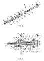
- the plug (10) includes a cylindrical shaft (11) that at one end has a threaded shank (12) and at the other end, an integral boss, plug or disk (13) so as to form an integral shaft component (14); the disk (13) has an inner bevelled or truncated cone-like peripheral surface (13'), as shown.
- the shaft (11) defines an internal bore (15) communicating with a flaring outer or distal end (16) that acts as an attachment means to communicate the bore to a water pressure source that, during testing, acts as a pressure media as will be explained.
- the bore (15) extends approximately midway into and along the longitudinal axis of the shaft (11), as more clearly seen in phantom in Figure 2 and in the cross section Figure 2B, and communicates with diametrically oriented channels (17), which communicate to the outside diameter surface of the shaft (11) - see Figure 2B.
- the shaft (11) is adapted to pass through an annular piece, sometimes referred to as the annulus, generally referenced as (20) having an internal bore (21) sized larger than the external diameter of the shaft (11) and having at least a radial bore, shown in figures 1 and 2 as two radially oppositely disposed channels (22) that communicate between a stepped annular recess (23) exteriorly circumscribing the centre portion of the annulus (20) with the (24) and (25), with their respective outer truncated annular surfaces (24') and (25') being bevelled inwardly from centre to perimeter.
- an annular piece sometimes referred to as the annulus, generally referenced as (20) having an internal bore (21) sized larger than the external diameter of the shaft (11) and having at least a radial bore, shown in figures 1 and 2 as two radially oppositely disposed channels (22) that communicate between a stepped annular recess (23) exteriorly circumscribing the centre portion of the annulus (20) with the (24) and (25),
- annulus (26) whose inner bore is larger than the outer diameter of the threaded shaft (12) so as to accommodate its passing there-through with space, the annulus having an interface (26') as a reversibly bevelled annular conical surface, and its outer face, preferably orthogonal to the longitudinal axis of the bore, yet having a stepped bore of slightly larger diameter at the interface between this space and the inner bore of the annulus so as to define a channeled race (26 r ) which accommodates a smaller elastomeric ring (R 3 ), as will be explained.
- the obverse surface (26') is a reversibly bevelled annular conical surface, which might also be “truncated", as are clearly seen in Figures 2, 2A and 2B.
- a second boss in the form of an annular collar (27) has its inner bore sized to accommodate the threaded shaft, to mate with a threaded nut (28) which is adapted to thread onto the shaft and to compress all the components of the plug referred above into one integral unit.
- annular sealing between juxtaposed bevelled surfaces (13') and (24') there is an elastomeric annular ring (R 1 ); similarly, there is an elastomeric annular ring (R 2 ) juxtaposed between truncated conical annular surfaces (25') and (26'), an elastomeric annular seal (R 3 ) which nests into the annular race (26 r ).
- the inner diameter of the annular race is sized to frictionally engage the outer diameter of the shaft (11) so as to provide a sealing fit as will be explained.
- Additional water pressure is applied so as to increase the pressure of water within space (S)
- the pressure of water within space (S) can be measured by a hydrostatic device, not shown, while observing the outside of the weld interface (30) to see whether any leakage occurs.
- Figures 1 through 3 become too heavy for workmen to carry thus, the same consists of a shaft (41) having an external end boss or disk (42) at one end and a threaded portion (43) at the opposite end, the shaft and disk defining a central bore (44).
- the disk (42) is welded at (45) to an annular end disk plate (46) whose inner margin (46') is a bevelled annulus to accommodate "O" ring (R 1 ).
- annular end disk (47) with a similar inner annular bevel (47') to accommodate annular ring (R 2 ) but the disk (47) also has an aperture there-through (48) which allows passage of a hydrostatic flooding and testing circuit, generally shown as (50) to extend there-through.
- the plug (40) includes an annular piece (60) defining an inner bore (61) which accommodates the shaft (41) and an outside circumferential race (62), which includes a hydrostatic filling channel (63) communicating with the testing circuit (50) in the fashion shown.
- the circuit (50) has a threaded hose (51) whose distal end threads into and sealingly mates with a corresponding thread (T) defined by the outer extremity of the bore (63) to make a fluid channel passing through the disk (47) and communicating with the race (62).
- the bore (44) acts as a venting channel to allow venting of the internal pipe (32) when the plug (40) is being inserted into the flanged pipe bounded by the peripheral weld (30) which is put in place to sealingly attach one to the other - see Figure 5. It may also be an advantage to conduct a second testing circuit which is referenced (65) to test everything that is to the right of the plug (40), as shown in that figure.
- the same bore (44) serves to vent the interior of the pipe (33) during insertion and removal of the plug (40) or, alternatively, accommodates a second circuit for testing the interior of the pipe (32), ifrequired, by utilising testing circuit (65).
- the testing circuit (50) includes a hydrostatic pressure gauge (P) communicating with the hose (51), a venting valve (V) having a switch (V 1 ), and a hydraulic fluid control valve (H) with its corresponding switch (H 1 ).
- Water is periodically allowed to flow through valve (H) into space (S) by opening (H 1 ) and closing (V 1 ) and venting of the air within the space (S) is achieved by reversing valve positions (H 1 ) and (V 1 ) so air vents out of valve (V) in accordance with the arrow there-above.
- This cycling occurs until the space (S) is filled with water and then pressuring of the water takes place so that the pressure gauge (P) registers the hydrostatic pressure on the circumferential weld seazh (30) to test the integrity of the same.
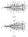
- FIG. 6 illustrates an embodiment of the invention wherein a single bolt tool that may be used for 1.9cm to 10.2cm (3 ⁇ 4 to 4 inch) diameter pipes is shown.
- the tool is generally shown at 400 comprising a centre shaft 402 that has a first end, a threaded second end and a through bore 418.
- the centre shaft 402 is fixed to a disk shaped back plate 401 through a hole 419 located at the centre of the back plate 401 so that the hole 419 and the bore 418 are coaxial.
- the outer diameter of the first end of the centre shaft 402 fits tightly into the hole 419 and the centre shaft 402 extends generally normal from the centre of the back plate 401.
- back plate 401 and centre shaft 402 comprise a unitary structure.
- a cylinder 404 is slidably mounted on the centre shaft 402 so that there is a clearance between the cylinder 404 and the centre shaft 402.
- the cylinder 404 includes a recess channel 417 that is continuous about the perimeter of the cylinder 404.
- a cavity is created between the pipe and the recess channel 417.
- At least one channel 405 extends from the recess channel 417 to the clearance region between the cylinder 404 and the centre shaft 402.
- a seal 403 is located between the back plate 401 and the cylinder 404 and a seal 406 is located between the cylinder and a front plate 407. Seals 403 and 406 preferably comprise "O" rings.
- a bore extends through the front plate 407 and the sleeve 408.
- the front plate 407 and sleeve 408 are mounted coaxially on the centre shaft 402.
- the front plate 407 comprises a first end adjacent to seal 406 and a second end attached to a sleeve 408.
- a clearance exists between the inner diameters of the front plate 407 and sleeve 408 and the outer diameter of the shaft 402.
- Sleeve 408 includes an inlet 409 and an outlet 416 located toward the second end of the centre shaft 402.
- front plate 407 and sleeve 408 comprise a unitary structure.
- a seal 410 is followed by a compression washer 411, a compression sleeve 412, a slip washer 413, and finally a nut 414.
- the threaded second end of the centre shaft 402 protrudes from the nut 414.
- the tool 400 is placed inside a pipe at a desired location.
- the nut 414 is then tightened on the centre shaft 402 in order to force all of the components to be tightly sandwiched together between the nut 414 and the back plate 401.
- the seals 403 and 406 on either side of the cylinder 404 are forced outward to meet the inner diameter of the pipe. This creates the cavity between the inside of the pipe and the cylinder 404.
- a medium such as water is then fed into the inlet 409. The cavity is bled until there is no air remaining in the cavity. If a hydrostatic operation is being performed, the water will be held in the cavity and pressurised. In a hydrodynamic operation, the water will be continuously fed into the inlet 409 and forced out of the outlet 416.
Landscapes
- Physics & Mathematics (AREA)
- General Physics & Mathematics (AREA)
- Examining Or Testing Airtightness (AREA)
- Investigating Strength Of Materials By Application Of Mechanical Stress (AREA)
- Rigid Pipes And Flexible Pipes (AREA)
- Forklifts And Lifting Vehicles (AREA)
- Fluid-Damping Devices (AREA)
- Insulators (AREA)
- Earth Drilling (AREA)
- Details Of Indoor Wiring (AREA)
- Thermal Insulation (AREA)
- Length Measuring Devices With Unspecified Measuring Means (AREA)
- Investigating Or Analyzing Materials By The Use Of Magnetic Means (AREA)
Claims (7)
- Vorrichtung (400) zum Abschotten oder Prüfen eines Rohrabschnitts mit innerem Durchmesser, umfassend:wobei die Vorrichtung (400) ferner einen sich durch den ringförmigen Körper (404) und die beiden Vorsprünge (401, 407) erstreckenden Schaft (402) enthält, welcher ein erstes und ein zweites Ende aufweist, wobei ein erster Vorsprung (401) der beiden Vorsprünge an dem ersten Ende des Schafts (402) befestigt ist und die Druckeinrichtung (414) am zweiten Ende des Schafts (402) angeordnet ist;a) einen ringförmigen Körper (404) mit in entgegengesetzte Richtungen weisenden ringförmigen Stirnflächen, der auf seinem äußeren Umfang eine Ausnehmung (417) definiert;b) ein Paar von Vorsprüngen (401, 407), die jeweils an entgegengesetzten Enden des ringförmigen Körpers (404) koaxial mit diesem angeordnet sind;c) ein Paar von ringförmigen Federelementen (403, 406), die jeweils zwischen die Vorsprünge (401, 407) und die ringförmigen Stirnflächen koaxial eingefügt sind;d) Einrichtung (414, 402, 408) zum jeweiligen Drücken der Vorsprünge (401, 407) in Richtung des ringförmigen Körpers (404) und damit zum Verformen der Federelemente (403, 406) in radial nach außen gerichteter Richtung gegen die innere Oberfläche des Rohrs, so daß ein Siegel dazwischen gebildet wird, wodurch ein erster versiegelter ringförmiger Raum zwischen der Ausnehmung (417) auf dem ringförmigen Körper (404), der inneren Oberfläche des Rohrs und den Federelementen (403, 406) definiert wird, wenn die Vorrichtung (400) in Gebrauch ist;e) Einrichtung (405, 409, 416) zum Einführen eines Fluids in den ringförmigen Raum, wobei die Einrichtung einen ersten Kanal (405, 409) zum Einführen des Fluids in den ringförmigen Raum und einen zweiten Kanal (405, 416) zum Auslassen von Luft aus dem ringförmigen Raum oder zum Ermöglichen von Fluidzirkulation durch den ringförmigen Raum umfaßt;f) einen sich durch die Vorrichtung (400) erstreckenden Kanal (418), um Kommunikation zwischen den inneren Abschnitten des Rohrs an den gegenüberliegenden Enden der Vorrichtung (400) zu gewährleisten;
und wobei der zweite Vorsprung (407) der beiden Vorsprünge eine daran befestigte Hülse (408) enthält, wobei die Hülse (408) sich über einen Abschnitt des Schafts (402) erstreckt und zwischen der Druckeinrichtung (414) und dem zweiten Vorsprung (407) angeordnet ist und einen größeren Durchmesser als der Schaft (402) hat, wodurch zwischen der Hülse (408) und dem Schaft (402) ein zweiter ringförmiger Raum gebildet wird, der bezüglich des Fluids in Kommunikation mit der Einrichtung (405) zum Einführen des Fluids steht, und wobei die Hülse (406) Schlitze (409, 416) zum Durchleiten eines Fluids durch den zweiten ringförmigen Raum enthält. - Vorrichtung nach Anspruch 1, wobei sich der Schaft (402) im wesentlichen koaxial durch den ringförmigen Körper (404) und die beiden Vorsprünge (401, 407) erstreckt.
- Vorrichtung nach Anspruch 2, wobei der Kanal eine sich durch den Schaft (402) erstreckende Bohrung (418) aufweist.
- Vorrichtung nach Anspruch 3, wobei. der ringförmige Körper (404) schiebbar auf dem Schaft (402) gesetzt ist, wodurch ein dritter ringförmiger Raum zwischen dem Schaft (402) und dem ringförmigen Körper (404) entsteht, wobei der zweite und der dritte ringförmige Raum bezüglich des Fluids miteinander kommunizieren.
- Vorrichtung nach Anspruch 4, wobei der erste und der zweite Kanal radial durch den ringförmigen Körper (404) verlaufende öffnungen (405) aufweisen, um die Kommunikation bezüglich des Fluids zwischen dem ersten und dem dritten ringförmigen Raum zu ermöglichen.
- Vorrichtung nach Anspruch 1, wobei die Druckeinrichtung eine Mutter (414) aufweist, die mit einem Gewindeabschnitt am zweiten Ende des Schafts (402) zusammenwirkt.
- Vorrichtung nach Anspruch 6, wobei die Mutter (414) an einem dem zweiten Vorsprung (407) gegenüberliegendes Ende (413) der Hülse (408) anliegt.
Priority Applications (1)
| Application Number | Priority Date | Filing Date | Title |
|---|---|---|---|
| DK99944195T DK1123494T3 (da) | 1998-09-23 | 1999-09-23 | Apparat til isolering eller testning af et rörsegment |
Applications Claiming Priority (3)
| Application Number | Priority Date | Filing Date | Title |
|---|---|---|---|
| US159226 | 1993-11-30 | ||
| US09/159,226 US6131441A (en) | 1996-12-02 | 1998-09-23 | Apparatus and method for isolating or testing a pipe segment |
| PCT/CA1999/000859 WO2000017619A1 (en) | 1998-09-23 | 1999-09-23 | Apparatus for isolating or testing a pipe segment |
Publications (2)
| Publication Number | Publication Date |
|---|---|
| EP1123494A1 EP1123494A1 (de) | 2001-08-16 |
| EP1123494B1 true EP1123494B1 (de) | 2004-07-21 |
Family
ID=22571638
Family Applications (1)
| Application Number | Title | Priority Date | Filing Date |
|---|---|---|---|
| EP99944195A Expired - Lifetime EP1123494B1 (de) | 1998-09-23 | 1999-09-23 | Vorrichtung zur abschottung oder prüfung eines rohrabschnitts |
Country Status (18)
| Country | Link |
|---|---|
| US (1) | US6131441A (de) |
| EP (1) | EP1123494B1 (de) |
| JP (2) | JP4567888B2 (de) |
| KR (1) | KR100878784B1 (de) |
| CN (1) | CN1291221C (de) |
| AT (1) | ATE271689T1 (de) |
| AU (1) | AU773488B2 (de) |
| BR (1) | BRPI9913953B8 (de) |
| CA (1) | CA2345335C (de) |
| DE (1) | DE69918851T2 (de) |
| DK (1) | DK1123494T3 (de) |
| ES (1) | ES2226431T3 (de) |
| LT (1) | LT4887B (de) |
| MX (1) | MXPA01004071A (de) |
| NO (1) | NO319541B1 (de) |
| PT (1) | PT1123494E (de) |
| WO (1) | WO2000017619A1 (de) |
| ZA (1) | ZA200103223B (de) |
Cited By (1)
| Publication number | Priority date | Publication date | Assignee | Title |
|---|---|---|---|---|
| DE202016003401U1 (de) | 2016-05-28 | 2016-06-09 | VIER Voith Industrial Services GmbH | Druckprüfvorrichtung |
Families Citing this family (58)
| Publication number | Priority date | Publication date | Assignee | Title |
|---|---|---|---|---|
| GB9900471D0 (en) * | 1999-01-09 | 1999-03-03 | Bedwell Leslie W | Apparatus and method for leak detection |
| US6672139B2 (en) | 1999-06-28 | 2004-01-06 | Inflow Products, Inc. | Leak testing device and a coupling therefor |
| US20040134260A1 (en) * | 1999-06-28 | 2004-07-15 | Inflow Products, Inc. | Leak testing device with a permanent coupling |
| US20080083267A1 (en) * | 1999-06-28 | 2008-04-10 | Pampinella Joseph A | Leak testing device with a permanent coupling |
| US6234007B1 (en) * | 1999-06-28 | 2001-05-22 | Inflow Products, Inc. | Leak testing device |
| US7325442B1 (en) | 1999-06-28 | 2008-02-05 | Inflow Products, Ltd. | Leak testing device with a permanent coupling |
| GB0015800D0 (en) * | 2000-06-29 | 2000-08-16 | Specialist Tools & Testing Ser | Tubular isolation |
| US6367313B1 (en) * | 2000-12-05 | 2002-04-09 | William M. Lubyk | Test plug |
| US6997041B1 (en) | 2001-04-11 | 2006-02-14 | Securus, Inc. | Dual slide gate valve and method for using same |
| US6675634B2 (en) | 2002-03-08 | 2004-01-13 | Est Group, Inc. | Branch pipe/tank nozzle test plug and method of use |
| USD488852S1 (en) | 2002-05-22 | 2004-04-20 | Inflow Products, Inc. | Conduit coupling |
| US7845211B2 (en) * | 2004-03-02 | 2010-12-07 | Car-Ber Investments Inc. | Apparatus and method for forming and testing lengths of pipe |
| CN100562730C (zh) | 2004-03-02 | 2009-11-25 | 卡泊尔投资公司 | 用于检测管道段的仪器 |
| AU2005321777B2 (en) * | 2004-12-30 | 2011-11-24 | Car-Ber Investments Inc. | Weld testing apparatus and methods for nozzles |
| US8256270B2 (en) * | 2005-04-14 | 2012-09-04 | Exxonmobil Upstream Research Company | Pipeline pressure tool |
| CA2625479A1 (en) * | 2005-10-06 | 2007-04-12 | Car-Ber Investments Inc. | Pipe testing tool with magnetic clamps |
| US8573655B2 (en) | 2005-10-06 | 2013-11-05 | Car-Ber Investments Inc. | Pipe sealing tool with external clamp |
| CA2625869A1 (en) * | 2005-10-14 | 2007-04-19 | Car-Ber Investments Inc. | Apparatus and method for testing or isolating a pipe segment with magnetically actuated sealing means |
| CA2535577C (en) * | 2006-02-08 | 2013-08-13 | Nav-Aids Ltee | Test adapter for aircraft static vent |
| USD574067S1 (en) | 2006-05-19 | 2008-07-29 | Inflow Products, Ltd. | Inline conduit coupling |
| CA2654711C (en) * | 2006-06-12 | 2015-01-06 | Car-Ber Investments Inc. | Nozzle testing apparatus and method |
| US20100186484A1 (en) * | 2006-08-07 | 2010-07-29 | Car-Ber Investments Inc. | Apparatus and Method for Isolating or Testing a Pipe Segment with Axial Reinforcement |
| CA2670034A1 (en) * | 2006-11-21 | 2008-05-29 | Car-Ber Investments Inc. | External pipe testing tool and testing method using same |
| CA2676531A1 (en) * | 2007-01-26 | 2008-08-07 | East Group, Inc. | Test plug and method for monitoring downstream conditions |
| CA2950142C (en) | 2008-08-15 | 2018-11-27 | Securus, Inc. | Pressure testing method and apparatus |
| EP2329181A4 (de) * | 2008-08-28 | 2015-12-09 | Car Ber Investments Inc | Interne arretiervorrichtung |
| CN102589817B (zh) * | 2012-02-16 | 2014-08-06 | 合肥市富华精密机械制造有限公司 | 一种焊缝检漏工具 |
| US9417153B2 (en) | 2012-09-27 | 2016-08-16 | Redline Detection, Llc | Balloon catheter apparatus for high pressure leak detection |
| US9869603B2 (en) | 2012-09-27 | 2018-01-16 | Redline Detection, Llc | Balloon catheter apparatus for internal combustion engine component leak detection and high pressure leak detection |
| ITRA20130010A1 (it) | 2013-04-05 | 2013-07-05 | Ipm Srl | Sistema di controllo del funzionamento della guarnizione di tenuta e del bicchiere di un tubo in materia plastica tipo pvc, ottenuto con processo di formatura con guarnizione integrata. |
| MX362998B (es) * | 2013-04-05 | 2019-03-01 | Car Ber Investments Inc | Aparato y metodo para aislar una seccion de un orificio de tuberia ascendente durante la renovacion del tubo ascendente. |
| CN103712755B (zh) * | 2013-06-14 | 2016-06-29 | 清华大学 | 一种模拟天然气在土壤中泄漏的试验装置 |
| US9903521B2 (en) | 2014-10-01 | 2018-02-27 | Richard L. Glenn | Upstream pipe plug |
| JP2016170107A (ja) * | 2015-03-13 | 2016-09-23 | トヨタ自動車株式会社 | リークチェック装置 |
| CA2979620A1 (en) * | 2015-03-31 | 2016-10-06 | Bombardier Inc. | Sealing assembly and plug for non-destructive inspection |
| US10161824B2 (en) * | 2015-05-11 | 2018-12-25 | HilFlo, LLC | Hydrostatic pressure test method and apparatus |
| US9933326B2 (en) | 2015-07-22 | 2018-04-03 | Redline Detection, Llc | System and method for detecting microscopic leaks |
| CN105067444B (zh) * | 2015-08-04 | 2017-07-04 | 新兴铸管股份有限公司 | 增压试验装置及其使用方法 |
| CN105628306B (zh) * | 2015-11-12 | 2018-02-02 | 济南吉利汽车零部件有限公司 | 试漏机封堵组件 |
| CN105757056B (zh) * | 2016-03-26 | 2018-08-17 | 宣月罗 | 一种封闭检漏装置 |
| CN105651472B (zh) * | 2016-04-11 | 2018-08-03 | 重庆燃气集团股份有限公司 | 燃气封堵和立管试压一体的装置及封堵试压方法 |
| US10739222B1 (en) | 2016-07-16 | 2020-08-11 | Victor Gossio | Magnetic pipeline pressure sensor/monitor with wireless transceiver |
| GB2569927B (en) * | 2016-10-05 | 2021-07-21 | Walter Knight Glenn | Valve assembly |
| US11268875B2 (en) | 2016-11-22 | 2022-03-08 | Redline Detection, Llc | Method and apparatus for fluid leak detection |
| CA3086047C (en) * | 2017-12-20 | 2023-01-24 | Vital Industrial Solutions Inc. | Assembly for engaging the interior of a pipe |
| KR102018708B1 (ko) * | 2018-02-23 | 2019-09-04 | (주) 중원엔지니어링 | 에어 리크 테스트 장치 |
| CA3012098A1 (en) | 2018-07-20 | 2020-01-20 | Clearwater Pipe Rentals Inc. | Weld test plugs and methods of use |
| KR101972703B1 (ko) * | 2018-09-12 | 2019-04-25 | 동명대학교산학협력단 | 파이프 유지보수용 유체흐름 차단장치 |
| US11156318B2 (en) | 2018-10-11 | 2021-10-26 | Reliance Worldwide Corporation | Test valve assembly with extraction mechanism |
| US11662049B2 (en) | 2018-10-11 | 2023-05-30 | Reliance Worldwide Corporation | Test valve assembly with extraction mechanism |
| CN110220067B (zh) * | 2019-06-10 | 2020-11-20 | 义乌市安航科技有限公司 | 一种燃气管网的密封保压封盖 |
| CN110646863B (zh) * | 2019-09-03 | 2022-04-29 | 合肥江航飞机装备股份有限公司 | 一种管道排气检测方法 |
| KR102361019B1 (ko) * | 2020-04-29 | 2022-02-08 | 세원이앤씨(주) | 튜브 투 튜브시트의 이너보어 용접부 검사장치 |
| CN112345164B (zh) * | 2020-11-03 | 2022-12-16 | 江苏华日圣油气井下工具有限公司 | 一种套管密封测试用校准胶塞 |
| CN112161877B (zh) * | 2020-12-03 | 2021-02-19 | 胜利新大新材料股份有限公司 | 一种管道试压设备 |
| US12420641B2 (en) | 2021-06-25 | 2025-09-23 | Redline Detection, Llc | Leak detection system for vehicle battery environment and related methodology |
| US12523563B2 (en) * | 2021-11-30 | 2026-01-13 | John C. Lausch | Plugs for anchoring within equipment and methods of use for pressure testing |
| CN118997690B (zh) * | 2024-09-19 | 2025-03-07 | 临沂市自然资源和规划局 | 一种水文地质勘探分层止水装置 |
Family Cites Families (40)
| Publication number | Priority date | Publication date | Assignee | Title |
|---|---|---|---|---|
| US1710439A (en) * | 1926-09-22 | 1929-04-23 | Taylor Orson | Pipe-pressure-testing plug |
| US1710739A (en) * | 1927-04-20 | 1929-04-30 | Int Cigar Mach Co | Wrapper-carrier suction control |
| US1757724A (en) * | 1928-02-17 | 1930-05-06 | Smith Corp A O | Packing appliance for pipe testing |
| GB329401A (en) * | 1929-02-22 | 1930-05-22 | Frederick Leonard Ball | Improvements in or relating to apparatus for testing pipe joints for leakage |
| US1841974A (en) * | 1929-08-31 | 1932-01-19 | Naylor Pipe Company | Closure device |
| FR826980A (fr) * | 1936-10-27 | 1938-04-13 | Deutsche Roehrenwerke Ag | Procédé et dispositif de contrôle de l'étanchéité des bouts de tube et raccords pour tubes et tuyaux |
| US2241525A (en) * | 1937-12-10 | 1941-05-13 | Robert Frenkel | Backpedaling brake device |
| US2241526A (en) * | 1939-09-12 | 1941-05-13 | Nat Tube Co | Pipe joint tester |
| US2342616A (en) * | 1941-11-04 | 1944-02-22 | James D O'brien | Leakage testing device |
| US2443944A (en) * | 1943-12-10 | 1948-06-22 | Cameron Iron Works Inc | Means for sealing and testing wellhead connections |
| US2873764A (en) * | 1955-07-06 | 1959-02-17 | Lombard Corp | Pipe end sealing apparatus for use in the pressure testing of pipes and tubes |
| DE1049124B (de) * | 1957-02-13 | 1959-01-22 | Walther & Cie Ag | Einrichtung zur Durchfuehrung der Dichtprobe von Anschweissnippeln fuer Kesseltrommeln, Sammler od. dgl. |
| GB826429A (en) * | 1957-05-02 | 1960-01-06 | Frederick George Hutchings Hay | A device for sealing into the bore of a tube |
| US3071960A (en) * | 1958-12-29 | 1963-01-08 | Willard E Knapp | Tubular testing apparatus with expandable back-up members and method of using same |
| US3338088A (en) * | 1965-10-18 | 1967-08-29 | Price Brothers Company Inc | Means for testing joints for large diameter pipe |
| US3483894A (en) * | 1966-04-07 | 1969-12-16 | Us Navy | High pressure pipe test plug |
| DE1550004B1 (de) * | 1967-01-07 | 1969-12-18 | Kieserling & Albrecht | Vorrichtung zum einseitigen Verschliessen und Einspannen von Hohlkoerpern,insbesondere von Rohren bei Druckproben |
| US3503249A (en) * | 1968-05-10 | 1970-03-31 | Joseph Frank Dumond | Tool for testing pipe joints |
| DE1813589A1 (de) * | 1968-12-10 | 1970-06-25 | Kernforschung Gmbh Ges Fuer | Verschlusseinrichtung fuer gerade Rohre |
| US3583239A (en) * | 1969-10-10 | 1971-06-08 | Nasa | Tube sealing device |
| US3712115A (en) * | 1970-10-09 | 1973-01-23 | Lofaso G | Pipe testing apparatus |
| JPS5146070Y2 (de) * | 1971-02-22 | 1976-11-08 | ||
| US3803901A (en) * | 1972-10-10 | 1974-04-16 | Taylor Wilson Mfg Co | Pipe tester |
| JPS52155591A (en) * | 1976-06-21 | 1977-12-24 | Nippon Rotsukuraapaipu Kk | Joint tester for small bore |
| US4083230A (en) * | 1977-02-03 | 1978-04-11 | Romco Pipe Testing, Inc. | Tubing testing tool |
| US4192177A (en) * | 1978-01-09 | 1980-03-11 | Huntington Alloys, Inc. | Apparatus and method for pressure testing of tubular bodies |
| DE3007726A1 (de) * | 1980-02-29 | 1981-09-17 | Klöckner-Humboldt-Deutz AG, 5000 Köln | Lenkrad fuer ein kraftfahrzeug, insbesondere fuer eine zugmaschine |
| US4381800A (en) * | 1981-08-31 | 1983-05-03 | Thaxton Inc. | Pipe tester plug |
| JPS59206735A (ja) * | 1983-05-11 | 1984-11-22 | R Kogyo Kk | 管筒類の流体漏洩試験方法及び管筒類の流体漏洩試験機 |
| US4574618A (en) * | 1984-05-21 | 1986-03-11 | Combustion Engineering, Inc. | Leak detection method and apparatus |
| DE3608814C1 (de) * | 1986-03-15 | 1987-08-13 | Weatherford Oil Tool | Geraet zum Pruefen der Gasdichtigkeit von Verbindungen zwischen Rohrstuecken |
| JPS6351255U (de) * | 1986-09-22 | 1988-04-06 | ||
| JPH0199037U (de) * | 1987-12-22 | 1989-07-03 | ||
| JPH0239141A (ja) * | 1988-07-29 | 1990-02-08 | Canon Inc | X線撮影装置 |
| JPH0239141U (de) * | 1988-09-08 | 1990-03-15 | ||
| US5204079A (en) * | 1991-02-15 | 1993-04-20 | Standard Oil Company | HCN by catalytic ammoxidation of crude acetonitrile |
| US5307841A (en) * | 1992-08-10 | 1994-05-03 | Rectorseal Corporation | Test plug for waste pipe |
| US5529066A (en) | 1994-06-27 | 1996-06-25 | Cb-Carmel Biotechnology Ltd. | Implantable capsule for enhancing cell electric signals |
| AU718949B2 (en) * | 1995-01-23 | 2000-05-04 | Car-Ber Investments Inc. | Test plug for pipes |
| JPH09105698A (ja) * | 1995-10-11 | 1997-04-22 | Kubota Corp | 管継手の密閉性検査装置 |
-
1998
- 1998-09-23 US US09/159,226 patent/US6131441A/en not_active Expired - Lifetime
-
1999
- 1999-09-23 WO PCT/CA1999/000859 patent/WO2000017619A1/en not_active Ceased
- 1999-09-23 BR BRPI9913953A patent/BRPI9913953B8/pt not_active IP Right Cessation
- 1999-09-23 CN CNB99812592XA patent/CN1291221C/zh not_active Expired - Fee Related
- 1999-09-23 DE DE69918851T patent/DE69918851T2/de not_active Expired - Lifetime
- 1999-09-23 JP JP2000571230A patent/JP4567888B2/ja not_active Expired - Lifetime
- 1999-09-23 PT PT99944195T patent/PT1123494E/pt unknown
- 1999-09-23 CA CA002345335A patent/CA2345335C/en not_active Expired - Lifetime
- 1999-09-23 ES ES99944195T patent/ES2226431T3/es not_active Expired - Lifetime
- 1999-09-23 AT AT99944195T patent/ATE271689T1/de active
- 1999-09-23 EP EP99944195A patent/EP1123494B1/de not_active Expired - Lifetime
- 1999-09-23 DK DK99944195T patent/DK1123494T3/da active
- 1999-09-23 MX MXPA01004071A patent/MXPA01004071A/es active IP Right Grant
- 1999-09-23 AU AU57238/99A patent/AU773488B2/en not_active Ceased
- 1999-09-23 KR KR1020017003759A patent/KR100878784B1/ko not_active Expired - Fee Related
-
2001
- 2001-03-22 LT LT2001027A patent/LT4887B/lt not_active IP Right Cessation
- 2001-03-23 NO NO20011521A patent/NO319541B1/no not_active IP Right Cessation
- 2001-04-20 ZA ZA2001/03223A patent/ZA200103223B/en unknown
-
2010
- 2010-06-23 JP JP2010142471A patent/JP4846866B2/ja not_active Expired - Lifetime
Cited By (2)
| Publication number | Priority date | Publication date | Assignee | Title |
|---|---|---|---|---|
| DE202016003401U1 (de) | 2016-05-28 | 2016-06-09 | VIER Voith Industrial Services GmbH | Druckprüfvorrichtung |
| EP3249374A1 (de) | 2016-05-28 | 2017-11-29 | Veltec GmbH | Druckprüfvorrichtung |
Also Published As
| Publication number | Publication date |
|---|---|
| DE69918851T2 (de) | 2005-08-18 |
| AU773488B2 (en) | 2004-05-27 |
| ATE271689T1 (de) | 2004-08-15 |
| CN1291221C (zh) | 2006-12-20 |
| DE69918851D1 (de) | 2004-08-26 |
| CA2345335A1 (en) | 2000-03-30 |
| JP2003524759A (ja) | 2003-08-19 |
| LT4887B (lt) | 2002-02-25 |
| PT1123494E (pt) | 2004-12-31 |
| NO319541B1 (no) | 2005-08-29 |
| DK1123494T3 (da) | 2004-11-29 |
| JP2010237224A (ja) | 2010-10-21 |
| KR20010085839A (ko) | 2001-09-07 |
| LT2001027A (en) | 2001-10-25 |
| US6131441A (en) | 2000-10-17 |
| CA2345335C (en) | 2008-11-18 |
| WO2000017619A1 (en) | 2000-03-30 |
| ZA200103223B (en) | 2002-06-26 |
| ES2226431T3 (es) | 2005-03-16 |
| CN1361862A (zh) | 2002-07-31 |
| MXPA01004071A (es) | 2003-09-22 |
| JP4846866B2 (ja) | 2011-12-28 |
| EP1123494A1 (de) | 2001-08-16 |
| JP4567888B2 (ja) | 2010-10-20 |
| NO20011521L (no) | 2001-05-23 |
| BR9913953B1 (pt) | 2013-05-21 |
| AU5723899A (en) | 2000-04-10 |
| KR100878784B1 (ko) | 2009-01-14 |
| BRPI9913953B8 (pt) | 2017-03-14 |
| NO20011521D0 (no) | 2001-03-23 |
| BR9913953A (pt) | 2001-06-12 |
Similar Documents
| Publication | Publication Date | Title |
|---|---|---|
| EP1123494B1 (de) | Vorrichtung zur abschottung oder prüfung eines rohrabschnitts | |
| US5844127A (en) | Apparatus for isolating or testing a pipe segment | |
| US4171142A (en) | Leak repair clamp | |
| US6299216B1 (en) | Joints | |
| US3485516A (en) | Double-pipe line flange connection | |
| CA1170921A (en) | Leak detection apparatus and method for use with tube and tube sheet joints | |
| US5024079A (en) | Test plug for flanged pipes | |
| US3377087A (en) | Union for connecting conduits | |
| US3679235A (en) | Pipe swivel joint for corrosive fluids | |
| EP0162201B1 (de) | Vorrichtung zum Nachweis von Lecken | |
| US4770207A (en) | Fluidic system | |
| WO2003027561A1 (en) | An arrangement for monitoring and/or testing of flange joints | |
| US4353580A (en) | Apparatus for removably attaching a pipe | |
| EP0753135B1 (de) | Teststopfen für rohre | |
| JPH0158398B2 (de) | ||
| US4375297A (en) | Quick coupling device | |
| JPH10267782A (ja) | 水圧試験機能付き管継手構造及びそのパッキング | |
| US5201344A (en) | Emissions eliminator blind | |
| CA2196523C (en) | Test plug for pipes | |
| CA2141956A1 (en) | Test plug for pipes | |
| US4244209A (en) | Testing of fluidic devices | |
| KR100315394B1 (ko) | 보수용파이프커플링 | |
| US4158304A (en) | Testing of fluidic devices | |
| AU736059C (en) | Joints | |
| KR870003370Y1 (ko) | 관누출 검사용 밀폐기(Closure) |
Legal Events
| Date | Code | Title | Description |
|---|---|---|---|
| PUAI | Public reference made under article 153(3) epc to a published international application that has entered the european phase |
Free format text: ORIGINAL CODE: 0009012 |
|
| 17P | Request for examination filed |
Effective date: 20010418 |
|
| AK | Designated contracting states |
Kind code of ref document: A1 Designated state(s): AT BE CH CY DE DK ES FI FR GB GR IE IT LI LU MC NL PT SE |
|
| 17Q | First examination report despatched |
Effective date: 20020604 |
|
| GRAP | Despatch of communication of intention to grant a patent |
Free format text: ORIGINAL CODE: EPIDOSNIGR1 |
|
| RTI1 | Title (correction) |
Free format text: APPARATUS FOR ISOLATING OR TESTING A PIPE SEGMENT |
|
| GRAS | Grant fee paid |
Free format text: ORIGINAL CODE: EPIDOSNIGR3 |
|
| GRAA | (expected) grant |
Free format text: ORIGINAL CODE: 0009210 |
|
| AK | Designated contracting states |
Kind code of ref document: B1 Designated state(s): AT BE CH CY DE DK ES FI FR GB GR IE IT LI LU MC NL PT SE |
|
| REG | Reference to a national code |
Ref country code: GB Ref legal event code: FG4D |
|
| REG | Reference to a national code |
Ref country code: CH Ref legal event code: EP |
|
| REG | Reference to a national code |
Ref country code: IE Ref legal event code: FG4D |
|
| REF | Corresponds to: |
Ref document number: 69918851 Country of ref document: DE Date of ref document: 20040826 Kind code of ref document: P |
|
| PG25 | Lapsed in a contracting state [announced via postgrant information from national office to epo] |
Ref country code: LU Free format text: LAPSE BECAUSE OF NON-PAYMENT OF DUE FEES Effective date: 20040923 |
|
| PG25 | Lapsed in a contracting state [announced via postgrant information from national office to epo] |
Ref country code: MC Free format text: LAPSE BECAUSE OF NON-PAYMENT OF DUE FEES Effective date: 20040930 |
|
| REG | Reference to a national code |
Ref country code: SE Ref legal event code: TRGR |
|
| REG | Reference to a national code |
Ref country code: CH Ref legal event code: NV Representative=s name: E. BLUM & CO. PATENTANWAELTE |
|
| REG | Reference to a national code |
Ref country code: DK Ref legal event code: T3 |
|
| REG | Reference to a national code |
Ref country code: GR Ref legal event code: EP Ref document number: 20040403593 Country of ref document: GR |
|
| REG | Reference to a national code |
Ref country code: PT Ref legal event code: SC4A Free format text: AVAILABILITY OF NATIONAL TRANSLATION Effective date: 20041020 |
|
| REG | Reference to a national code |
Ref country code: ES Ref legal event code: FG2A Ref document number: 2226431 Country of ref document: ES Kind code of ref document: T3 |
|
| PLBE | No opposition filed within time limit |
Free format text: ORIGINAL CODE: 0009261 |
|
| STAA | Information on the status of an ep patent application or granted ep patent |
Free format text: STATUS: NO OPPOSITION FILED WITHIN TIME LIMIT |
|
| ET | Fr: translation filed | ||
| 26N | No opposition filed |
Effective date: 20050422 |
|
| REG | Reference to a national code |
Ref country code: GB Ref legal event code: 732E |
|
| REG | Reference to a national code |
Ref country code: PT Ref legal event code: PC4A Owner name: CAR-BER INVESTMENTS INC., CA Effective date: 20050810 |
|
| NLS | Nl: assignments of ep-patents |
Owner name: CAR-BER INVESTMENTS INC. Effective date: 20050817 |
|
| REG | Reference to a national code |
Ref country code: CH Ref legal event code: PUE Owner name: CAR-BER INVESTMENTS INC. Free format text: BERUBE, GUY#880 GUTHRIE DRIVE#SARNIA, ONTARIO N7V 1Y3 (CA) $ CARSON, GLENN#1362 CATHEART BOULEVARD#SARNIA, ONTARIO N7S 5G5 (CA) -TRANSFER TO- CAR-BER INVESTMENTS INC.#911 MICHIGAN AVENUE#POINT EDWARD, ONTARIO N7V 1H2 (CA) Ref country code: CH Ref legal event code: NV Representative=s name: A. BRAUN, BRAUN, HERITIER, ESCHMANN AG PATENTANWAE |
|
| REG | Reference to a national code |
Ref country code: FR Ref legal event code: TP |
|
| REG | Reference to a national code |
Ref country code: ES Ref legal event code: PC2A |
|
| PGFP | Annual fee paid to national office [announced via postgrant information from national office to epo] |
Ref country code: CH Payment date: 20071015 Year of fee payment: 9 |
|
| PGFP | Annual fee paid to national office [announced via postgrant information from national office to epo] |
Ref country code: CY Payment date: 20071107 Year of fee payment: 9 |
|
| REG | Reference to a national code |
Ref country code: CH Ref legal event code: PFA Owner name: CAR-BER INVESTMENTS INC. Free format text: CAR-BER INVESTMENTS INC.#911 MICHIGAN AVENUE#POINT EDWARD, ONTARIO N7V 1H2 (CA) -TRANSFER TO- CAR-BER INVESTMENTS INC.#911 MICHIGAN AVENUE#POINT EDWARD, ONTARIO N7V 1H2 (CA) |
|
| REG | Reference to a national code |
Ref country code: CH Ref legal event code: PL |
|
| PG25 | Lapsed in a contracting state [announced via postgrant information from national office to epo] |
Ref country code: CY Free format text: LAPSE BECAUSE OF NON-PAYMENT OF DUE FEES Effective date: 20080923 |
|
| PG25 | Lapsed in a contracting state [announced via postgrant information from national office to epo] |
Ref country code: LI Free format text: LAPSE BECAUSE OF NON-PAYMENT OF DUE FEES Effective date: 20080930 Ref country code: CH Free format text: LAPSE BECAUSE OF NON-PAYMENT OF DUE FEES Effective date: 20080930 |
|
| PGFP | Annual fee paid to national office [announced via postgrant information from national office to epo] |
Ref country code: IT Payment date: 20100925 Year of fee payment: 12 |
|
| PGFP | Annual fee paid to national office [announced via postgrant information from national office to epo] |
Ref country code: IE Payment date: 20110926 Year of fee payment: 13 |
|
| PGFP | Annual fee paid to national office [announced via postgrant information from national office to epo] |
Ref country code: FI Payment date: 20110928 Year of fee payment: 13 Ref country code: ES Payment date: 20110926 Year of fee payment: 13 Ref country code: AT Payment date: 20110901 Year of fee payment: 13 Ref country code: SE Payment date: 20110928 Year of fee payment: 13 Ref country code: PT Payment date: 20110831 Year of fee payment: 13 Ref country code: GR Payment date: 20110927 Year of fee payment: 13 |
|
| PGFP | Annual fee paid to national office [announced via postgrant information from national office to epo] |
Ref country code: DK Payment date: 20110927 Year of fee payment: 13 |
|
| PGFP | Annual fee paid to national office [announced via postgrant information from national office to epo] |
Ref country code: GB Payment date: 20120925 Year of fee payment: 14 |
|
| PGFP | Annual fee paid to national office [announced via postgrant information from national office to epo] |
Ref country code: FR Payment date: 20121001 Year of fee payment: 14 |
|
| PGFP | Annual fee paid to national office [announced via postgrant information from national office to epo] |
Ref country code: DE Payment date: 20120927 Year of fee payment: 14 Ref country code: BE Payment date: 20120925 Year of fee payment: 14 |
|
| PGFP | Annual fee paid to national office [announced via postgrant information from national office to epo] |
Ref country code: NL Payment date: 20120924 Year of fee payment: 14 |
|
| REG | Reference to a national code |
Ref country code: PT Ref legal event code: MM4A Free format text: LAPSE DUE TO NON-PAYMENT OF FEES Effective date: 20130325 |
|
| PG25 | Lapsed in a contracting state [announced via postgrant information from national office to epo] |
Ref country code: FI Free format text: LAPSE BECAUSE OF NON-PAYMENT OF DUE FEES Effective date: 20120923 Ref country code: SE Free format text: LAPSE BECAUSE OF NON-PAYMENT OF DUE FEES Effective date: 20120924 |
|
| REG | Reference to a national code |
Ref country code: SE Ref legal event code: EUG |
|
| REG | Reference to a national code |
Ref country code: AT Ref legal event code: MM01 Ref document number: 271689 Country of ref document: AT Kind code of ref document: T Effective date: 20120923 |
|
| REG | Reference to a national code |
Ref country code: GR Ref legal event code: ML Ref document number: 20040403593 Country of ref document: GR Effective date: 20130404 |
|
| PG25 | Lapsed in a contracting state [announced via postgrant information from national office to epo] |
Ref country code: PT Free format text: LAPSE BECAUSE OF NON-PAYMENT OF DUE FEES Effective date: 20130325 |
|
| REG | Reference to a national code |
Ref country code: DK Ref legal event code: EBP |
|
| REG | Reference to a national code |
Ref country code: IE Ref legal event code: MM4A |
|
| PG25 | Lapsed in a contracting state [announced via postgrant information from national office to epo] |
Ref country code: AT Free format text: LAPSE BECAUSE OF NON-PAYMENT OF DUE FEES Effective date: 20120923 Ref country code: IE Free format text: LAPSE BECAUSE OF NON-PAYMENT OF DUE FEES Effective date: 20120923 |
|
| PG25 | Lapsed in a contracting state [announced via postgrant information from national office to epo] |
Ref country code: IT Free format text: LAPSE BECAUSE OF NON-PAYMENT OF DUE FEES Effective date: 20120923 Ref country code: GR Free format text: LAPSE BECAUSE OF NON-PAYMENT OF DUE FEES Effective date: 20130404 |
|
| REG | Reference to a national code |
Ref country code: ES Ref legal event code: FD2A Effective date: 20131030 |
|
| PG25 | Lapsed in a contracting state [announced via postgrant information from national office to epo] |
Ref country code: ES Free format text: LAPSE BECAUSE OF NON-PAYMENT OF DUE FEES Effective date: 20120924 Ref country code: DK Free format text: LAPSE BECAUSE OF NON-PAYMENT OF DUE FEES Effective date: 20121001 |
|
| BERE | Be: lapsed |
Owner name: *CAR-BER INVESTMENTS INC. Effective date: 20130930 |
|
| REG | Reference to a national code |
Ref country code: NL Ref legal event code: V1 Effective date: 20140401 |
|
| GBPC | Gb: european patent ceased through non-payment of renewal fee |
Effective date: 20130923 |
|
| REG | Reference to a national code |
Ref country code: DE Ref legal event code: R119 Ref document number: 69918851 Country of ref document: DE Effective date: 20140401 |
|
| REG | Reference to a national code |
Ref country code: FR Ref legal event code: ST Effective date: 20140530 |
|
| PG25 | Lapsed in a contracting state [announced via postgrant information from national office to epo] |
Ref country code: BE Free format text: LAPSE BECAUSE OF NON-PAYMENT OF DUE FEES Effective date: 20130930 Ref country code: GB Free format text: LAPSE BECAUSE OF NON-PAYMENT OF DUE FEES Effective date: 20130923 |
|
| PG25 | Lapsed in a contracting state [announced via postgrant information from national office to epo] |
Ref country code: FR Free format text: LAPSE BECAUSE OF NON-PAYMENT OF DUE FEES Effective date: 20130930 Ref country code: NL Free format text: LAPSE BECAUSE OF NON-PAYMENT OF DUE FEES Effective date: 20140401 Ref country code: DE Free format text: LAPSE BECAUSE OF NON-PAYMENT OF DUE FEES Effective date: 20140401 |