EP1123573B1 - Jeu de pieces pour constituer des conduits de cables d'un meuble de bureau - Google Patents
Jeu de pieces pour constituer des conduits de cables d'un meuble de bureau Download PDFInfo
- Publication number
- EP1123573B1 EP1123573B1 EP99953820A EP99953820A EP1123573B1 EP 1123573 B1 EP1123573 B1 EP 1123573B1 EP 99953820 A EP99953820 A EP 99953820A EP 99953820 A EP99953820 A EP 99953820A EP 1123573 B1 EP1123573 B1 EP 1123573B1
- Authority
- EP
- European Patent Office
- Prior art keywords
- profiled
- column
- portions
- rear wall
- grooves
- Prior art date
- Legal status (The legal status is an assumption and is not a legal conclusion. Google has not performed a legal analysis and makes no representation as to the accuracy of the status listed.)
- Expired - Lifetime
Links
- 230000007704 transition Effects 0.000 claims description 4
- 238000009434 installation Methods 0.000 claims description 2
- 230000000717 retained effect Effects 0.000 claims 3
- 230000008878 coupling Effects 0.000 description 3
- 238000010168 coupling process Methods 0.000 description 3
- 238000005859 coupling reaction Methods 0.000 description 3
- 238000013459 approach Methods 0.000 description 2
- 239000002131 composite material Substances 0.000 description 1
- 238000010276 construction Methods 0.000 description 1
Images

Classifications
-
- A—HUMAN NECESSITIES
- A47—FURNITURE; DOMESTIC ARTICLES OR APPLIANCES; COFFEE MILLS; SPICE MILLS; SUCTION CLEANERS IN GENERAL
- A47B—TABLES; DESKS; OFFICE FURNITURE; CABINETS; DRAWERS; GENERAL DETAILS OF FURNITURE
- A47B21/00—Tables or desks for office equipment, e.g. typewriters, keyboards
- A47B21/06—Tables or desks for office equipment, e.g. typewriters, keyboards characterised by means for holding, fastening or concealing cables
-
- H—ELECTRICITY
- H02—GENERATION; CONVERSION OR DISTRIBUTION OF ELECTRIC POWER
- H02G—INSTALLATION OF ELECTRIC CABLES OR LINES, OR OF COMBINED OPTICAL AND ELECTRIC CABLES OR LINES
- H02G3/00—Installations of electric cables or lines or protective tubing therefor in or on buildings, equivalent structures or vehicles
- H02G3/02—Details
- H02G3/04—Protective tubing or conduits, e.g. cable ladders or cable troughs
- H02G3/0462—Tubings, i.e. having a closed section
- H02G3/0487—Tubings, i.e. having a closed section with a non-circular cross-section
-
- H—ELECTRICITY
- H02—GENERATION; CONVERSION OR DISTRIBUTION OF ELECTRIC POWER
- H02G—INSTALLATION OF ELECTRIC CABLES OR LINES, OR OF COMBINED OPTICAL AND ELECTRIC CABLES OR LINES
- H02G3/00—Installations of electric cables or lines or protective tubing therefor in or on buildings, equivalent structures or vehicles
- H02G3/02—Details
- H02G3/04—Protective tubing or conduits, e.g. cable ladders or cable troughs
- H02G3/0437—Channels
Definitions
- the invention relates to a kit for cable ducts of a workstation furniture, which consists of several different, composable profile sections, on which molded connection elements on the inside and / or outside or molded.
- Such a kit is known from DE 196 10 347 C1.
- the one on the Fasteners formed on the inside are webs or grooves and serve for fastening cables and internals.
- For connecting the profile sections to the cable duct are complicated on the free longitudinal edges of the profile sections designed connecting and counter-connecting elements.
- the put together Cable channels serve primarily as horizontal channels can be connected at the front with vertical columns of the furniture frame, and have a relatively small recording space.
- the connecting grooves in the side legs of the column connection profile sections and the rear wall profile sections have a T-shaped cross section, and that on the inside of the column connection profile sections and the rear wall profile sections and at least part of the receiving grooves the connection profile sections T-shaped cross section exhibit.
- connection approaches of the connection profile sections provided with holes and by means of screws with the connecting grooves the column connection profile sections and the rear wall profile sections are screwed, then the colliding Profile sections are simply screwed together and the installation of devices in the cable duct is facilitated.
- connection profile section for the cable duct can also be provided that the side legs of the column connection profile sections and the rear wall profile sections in connection receiving grooves leak that is flush with the outside of the side legs complete and that in the opposing grooves at the ends of the side legs of the column connection profile section and rear wall profile section a flexible cover introduced and held therein.
- a positive reception of the column in the column holder of the Column connection profile section is achieved in that the Column connection profile sections on the outside in the end areas of the base leg have molded hollow chamber webs limit the pillar support, and that the facing side walls this hollow chamber webs the column holder to the outside continuously widening and with holding bars facing each other are provided.
- the holding bars make it easy to attach created for the cable duct on the column in that in the Column receptacles can be inserted with the holding bars are held and with hook strips in slots of the facing side walls the column can be attached. This can be done in the longitudinal direction use several holding slides.
- An embodiment is advantageous which is characterized in that the holding slide means Locking screw in the column holder are immovable.
- the holding bars of the holding slides thus defined are in the division of Slots arranged in the column and positioned so that the at the Column-suspended cable duct at several points along its length is held.
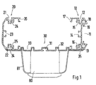
- Fig. 1 form a substantially U-shaped column connection profile section 11 and a substantially U-shaped rear wall profile section 20 the side legs of an open, U-shaped cable duct.
- a connecting profile section 30 forms the base leg of the cable duct.
- the outside of the column connection profile section 10 is with the hollow chamber webs 18 with a column receptacle 11 with molded on Retaining bars 19, in the form-fitting a vertical column 40 of the furniture frame can be introduced, as shown in Fig. 2.
- For fixing holding slides 50 are used, which are behind the holding webs 19 inserted and positioned with locking screws 52.
- the side wall of the column 40 facing the column holder 11 carries a series of horizontal slots 41 into which the hook strips 51 the holding slide 50 can be hooked in if this in the Division of the slots 41 positioned on the column connection profile section 10 are.
- T-shaped connecting grooves 12 and 13 formed in the connecting lugs 34 and 35 of a connecting profile section 30 can be inserted and screwed tight with screws 55, as shown in FIG. 2 shows.
- the connecting grooves 12 and 13 forming profile parts open screw channels 15 and 16 integrally formed, the additional in particular on the end face of the cable duct Offer connection options.
- the side legs of the column connection profile section 10 run in Grooves 17 from. The same applies to the side legs of the in Substantially U-shaped rear wall profile sections 20 with the receiving grooves 26 and the molded connection grooves 21 and 22.
- Die Connection groove 22 takes the connection projection 34 of the connection profile section in FIG. 1 30 on.
- the transitions from the side legs to the base leg of the rear wall profile section 20 beveled.
- the inside of the base leg of the rear wall section 20 carries an integrally formed fastening groove 23, like the base leg of the column connection profile section 10 with the fastening groove 14.
- In the area of the transitions from the side legs to the base leg of the rear wall profile section 20 are open screw channels 24 and 25 integrally molded, the other side fastening options Offer.
- the connecting profile sections 30 are essentially meandering Cross section with alternating on the inside and outside Receiving grooves 31, 32 and 33, for attaching internals and Structures such as Plug strips 80 or the like can be used with cover 81 are.
- a flexible cover 90 which is closed into each other facing receiving grooves 17 and 26 of column connection profile section 10 and rear wall profile section 20 is inserted.
- These flexible Covers can also only cover partial areas of the longitudinal dimension of the cable duct so as to compress the cover at certain points of the cable duct cables in and / or to be able to execute.
- the connecting grooves 12 and 21 of the column connection profile section 10 and the rear wall profile section 20th remain free so that they have grid bars 70 with a number of Can accommodate slots 71. Hooks can be inserted into these slots 71 60 can be hooked in Profile sections of a horizontal cable duct are used. On in this way, horizontal cable channels can be coupled, the Division of the slots 71 in the grid strips 70, the coupling points establish.
- the three different profile sections - column connection, rear wall and Connection profile section - allow the construction of closed and partially open vertical cable channels with a simple and unique mounting option on a vertical column 40 of the Furniture frame.
- connection of the profile sections easily and quickly executable with each other.
- the cable duct offers Attachment and mounting options on its interior and Outsides, in particular the simple coupling of horizontal Cable channels come into play as this is just in use flexible covers in the area of the coupling points the cable routing in the Workplace furniture significantly simplified.
Landscapes
- Engineering & Computer Science (AREA)
- Architecture (AREA)
- Civil Engineering (AREA)
- Structural Engineering (AREA)
- Installation Of Indoor Wiring (AREA)
- Tables And Desks Characterized By Structural Shape (AREA)
- Details Of Indoor Wiring (AREA)
- Rod-Shaped Construction Members (AREA)
- Circuits Of Receivers In General (AREA)
- Insulated Conductors (AREA)
Claims (13)
- Jeu de pièces détachées pour des conduits de câbles d'un meuble de poste de travail constitué de plusieurs sections de profilé différentes enfichables ensemble, sur lesquelles sont façonnés ou moulés, sur les faces intérieure et/ou extérieure, des éléments de liaison,
caractérisé en ce qu'il comprend trois sections de profilé différentes :a) des sections de profilé d'assemblage de poteaux (10) à section transversale sensiblement en forme de U, la branche de base étant formée sur la face extérieure en tant que logement de poteau (11), des rainures de liaison (12, 13) étant formées dans les faces extérieures des branches latérales et la face intérieure de la branche de base étant munie d'une rainure de fixation (14) façonnée,b) des sections de profilé de paroi arrière (20) à section transversale sensiblement en forme de U, la face intérieure de la branche de base étant munie d'une rainure de fixation (14) façonnée et des rainures de liaison (21, 22) étant moulées dans les faces extérieures des branches latérales, etc) des sections de profilé de liaison (30) à section transversale sensiblement en forme de méandres pour la liaison de la section de profilé d'assemblage de poteaux (10) à la section de profilé de paroi arrière (20), des rainures de logement (31, 32, 33) étant formées alternativement sur les faces intérieure et extérieure et les arêtes longitudinales se transformant en saillies de liaison (34, 35) qui peuvent être introduites dans les rainures de liaison (12, 13; 21, 22) des sections de profilé d'assemblage de poteaux et des sections de profilé de paroi arrière (10, 20) et peuvent être reliées à celles-ci. - Jeu de pièces détachées selon la revendication 1,
caractérisé en ce que les rainures de liaison (12, 13, 21, 22) dans les branches latérales des sections de profilé d'assemblage de poteaux (10) et des sections de profilé de paroi arrière (20) présentent une section transversale en forme de T. - Jeu de pièces détachées selon la revendication 1 ou 2,
caractérisé en ce que les rainures de logement sur les faces intérieures des sections de profilé d'assemblage de poteaux (10) et des sections de profilé de paroi arrière (20) ainsi qu'au moins une partie des rainures de logement (31) des sections de profilé de liaison (30) présentent une section transversale en forme de T. - Jeu de pièces détachées selon l'une des revendications 1 à 3,
caractérisé en ce que des canaux de vis (15, 16 ; 24, 25) ouverts sont formés dans la zone d'angle intérieur dans la zone des rainures de liaison (12, 13 ; 21, 22) des sections de profilé d'assemblage de poteaux (10) et des sections de profilé de paroi arrière (20). - Jeu de pièces détachées selon l'une des revendications 1 à 4,
caractérisé en ce que les branches latérales des sections de profilé d'assemblage de poteaux (10) et des sections de profilé de paroi arrière (20) se terminent en rainures de réception d'assemblage (17, 26) qui s'arrêtent en affleurement avec les faces extérieures des branches latérales. - Jeu de pièces détachées selon l'une des revendications 1 à 5,
caractérisé en ce que les transitions de la branche de base en les branches latérales des sections de paroi arrière (20) sont biseautées. - Jeu de pièces détachées selon l'une des revendications 1 à 6,
caractérisé en ce que les sections de profilé d'assemblage de poteaux (10) présentent, sur les faces extérieures, des âmes à chambre creuse (18) façonnées dans les zones d'extrémité de la branche de base, qui délimitent le logement de poteau (11) et que les parois latérales tournées l'une vers l'autre de ces âmes à chambre creuse (18) élargissent continuellement vers l'extérieur le logement de poteau (11) et sont munies de nervures d'arrêt (19) dirigées l'une vers l'autre. - Jeu de pièces détachées selon l'une des revendications 1 à 7,
caractérisé en ce que, dans le logement de poteau (11), peuvent être logés des coulisseaux de support (50) qui sont maintenus par les nervures d'arrêt (19) et peuvent être suspendus par des baguettes à crochet (51) dans des fentes (41) de la paroi latérale opposée du poteau (40). - Jeu de pièces détachées selon la revendication 8,
caractérisé en ce que les coulisseaux de support (50) peuvent être fixés sans pouvoir coulisser dans le logement de poteau (11) au moyen de vis d'arrêt (52). - Jeu de pièces détachées selon l'une des revendications 1 à 9,
caractérisé en ce que les saillies de liaison (34, 35) des sections de profilé de liaison (30) sont munies d'alésages et peuvent être vissées, au moyen de vis (55), aux rainures de liaison (13, 22) des sections de profilé d'assemblage de poteaux (10) et des sections de profilé de paroi arrière (20). - Jeu de pièces détachées selon l'une des revendications 1 à 10,
caractérisé en ce que des baguettes de quadrillage (70) avec une rangée de fentes (71) peuvent être introduites en glissant dans les rainures de liaison (12, 21) des sections de profilé d'assemblage de poteaux (10) et des sections de profilé de paroi arrière (20) et être maintenues dedans de manière imperdable et
que des crochets de suspension (60), qui sont montés frontalement dans des rainures de logement de sections de profilé se trouvant orthogonales à celles-ci, peuvent être accrochés dans les fentes. - Jeu de pièces détachées selon l'une des revendications 1 à 11,
caractérisé en ce qu'un recouvrement (90) flexible est monté dans les rainures de logement (17, 26) orientées l'une vers l'autre aux extrémités des branches latérales de la section de profilé d'assemblage de poteaux (10) et de la section de profilé de paroi arrière (20) et est maintenu dedans. - Jeu de pièces détachées selon l'une des revendications 1 à 12,
caractérisé en ce que des baguettes de connecteur (80), des boítes d'assemblage d'appareils et similaires peuvent être montées sur la face extérieure et/ou intérieure des sections de profilé de liaison (30) ainsi que sur la face intérieure des sections de profilé d'assemblage de poteaux et de paroi arrière (10 et 20).
Applications Claiming Priority (3)
| Application Number | Priority Date | Filing Date | Title |
|---|---|---|---|
| DE19848511 | 1998-10-21 | ||
| DE19848511A DE19848511C2 (de) | 1998-10-21 | 1998-10-21 | Bausatz für Kabelkanäle eines Arbeitsplatz-Möbels |
| PCT/EP1999/007732 WO2000024103A1 (fr) | 1998-10-21 | 1999-10-14 | Jeu de pieces pour constituer des conduits de cables d'un meuble de bureau |
Publications (2)
| Publication Number | Publication Date |
|---|---|
| EP1123573A1 EP1123573A1 (fr) | 2001-08-16 |
| EP1123573B1 true EP1123573B1 (fr) | 2002-09-18 |
Family
ID=7885174
Family Applications (1)
| Application Number | Title | Priority Date | Filing Date |
|---|---|---|---|
| EP99953820A Expired - Lifetime EP1123573B1 (fr) | 1998-10-21 | 1999-10-14 | Jeu de pieces pour constituer des conduits de cables d'un meuble de bureau |
Country Status (9)
| Country | Link |
|---|---|
| US (1) | US6528726B1 (fr) |
| EP (1) | EP1123573B1 (fr) |
| AT (1) | ATE224594T1 (fr) |
| BR (1) | BR9914637A (fr) |
| DE (2) | DE19848511C2 (fr) |
| DK (1) | DK1123573T3 (fr) |
| ES (1) | ES2181485T3 (fr) |
| PT (1) | PT1123573E (fr) |
| WO (1) | WO2000024103A1 (fr) |
Families Citing this family (6)
| Publication number | Priority date | Publication date | Assignee | Title |
|---|---|---|---|---|
| DE10159065A1 (de) * | 2001-12-01 | 2003-06-26 | Pierburg Gmbh | Halterung für elektro-pneumatische Bauteile |
| US7282650B2 (en) * | 2004-10-14 | 2007-10-16 | Lockheed Martin Corp. | Conduit gland |
| DE102007011141B4 (de) | 2007-03-07 | 2012-10-25 | Elabo Gmbh | Arbeitsmöbel mit Kabelkanal |
| DE102015000289B4 (de) * | 2015-01-17 | 2017-10-12 | Detlef Wittkopp | Kabelkanalsystem |
| US9825448B1 (en) * | 2015-07-14 | 2017-11-21 | Clayton Dean VanVolkinburg | Electrical raceway assembly and method of using the same |
| US10383435B1 (en) * | 2018-02-12 | 2019-08-20 | Inscape Corporation | Desking arrangement |
Family Cites Families (12)
| Publication number | Priority date | Publication date | Assignee | Title |
|---|---|---|---|---|
| DE2337628A1 (de) * | 1973-07-24 | 1975-02-06 | Intermercury Finance & Trad | Installationskanal |
| DE3426064C1 (de) | 1984-07-14 | 1986-01-16 | OBO Bettermann oHG, 5750 Menden | Trennwand für einen Kabelkanal |
| US4907767A (en) * | 1988-08-12 | 1990-03-13 | Hubbell Incorporated | Stackable modular duct assemblies |
| FR2654561B1 (fr) * | 1989-11-15 | 1992-01-24 | Boga Ingenierie | Gaine pour canalisations de systeme de distribution, et profile et procede de montage d'une telle gaine. |
| DE4007165C2 (de) | 1990-03-07 | 1995-11-16 | Kleinhuis Hermann Gmbh | Kabelkanal, wie Brüstungskanal, Geräteeinbaukanal od.dgl. |
| DE4012442A1 (de) * | 1990-04-19 | 1991-10-24 | Kleinhuis Hermann Gmbh | Versorgungskanal fuer elektrische energie |
| FR2686142B1 (fr) * | 1992-01-14 | 1994-04-22 | Mavil | Combinaison de troncons successifs de chemin de cables en matiere plastique et de moyen d'assemblage desdits troncons, et procede pour la mise en óoeuvre de cette combinaison. |
| JP3530654B2 (ja) | 1995-10-03 | 2004-05-24 | Smc株式会社 | コンジット |
| DE19610347C1 (de) * | 1996-03-18 | 1997-04-03 | Lampertz Fab Org | Kabelkanalsystem für Büroeinrichtungen, insbesondere für EDV-Arbeitsplätze o. dgl. |
| DE29610947U1 (de) * | 1996-06-24 | 1996-08-22 | Miranda, Giovanni, 78549 Spaichingen | Kabelkanalprofil |
| DE19821069A1 (de) * | 1998-05-12 | 1999-11-18 | Hilti Ag | Klammer für einen Kabelkanal |
| US6313405B1 (en) * | 1999-08-31 | 2001-11-06 | Cooper Technologies Company | Cable tray |
-
1998
- 1998-10-21 DE DE19848511A patent/DE19848511C2/de not_active Expired - Fee Related
-
1999
- 1999-10-14 US US09/807,912 patent/US6528726B1/en not_active Expired - Fee Related
- 1999-10-14 DE DE59902789T patent/DE59902789D1/de not_active Expired - Fee Related
- 1999-10-14 AT AT99953820T patent/ATE224594T1/de not_active IP Right Cessation
- 1999-10-14 ES ES99953820T patent/ES2181485T3/es not_active Expired - Lifetime
- 1999-10-14 EP EP99953820A patent/EP1123573B1/fr not_active Expired - Lifetime
- 1999-10-14 BR BR9914637-1A patent/BR9914637A/pt not_active IP Right Cessation
- 1999-10-14 DK DK99953820T patent/DK1123573T3/da active
- 1999-10-14 WO PCT/EP1999/007732 patent/WO2000024103A1/fr not_active Ceased
- 1999-10-14 PT PT99953820T patent/PT1123573E/pt unknown
Also Published As
| Publication number | Publication date |
|---|---|
| DE19848511A1 (de) | 2000-05-04 |
| DE19848511C2 (de) | 2001-05-31 |
| EP1123573A1 (fr) | 2001-08-16 |
| PT1123573E (pt) | 2003-01-31 |
| DK1123573T3 (da) | 2002-12-30 |
| ATE224594T1 (de) | 2002-10-15 |
| ES2181485T3 (es) | 2003-02-16 |
| DE59902789D1 (de) | 2002-10-24 |
| US6528726B1 (en) | 2003-03-04 |
| WO2000024103A1 (fr) | 2000-04-27 |
| BR9914637A (pt) | 2001-07-03 |
Similar Documents
| Publication | Publication Date | Title |
|---|---|---|
| EP0789944B1 (fr) | Baie formee de montants et d'entretoises de profondeur | |
| EP0939984B1 (fr) | Armoire de distribution | |
| DE4137836C1 (fr) | ||
| DE29623559U1 (de) | Rahmengestell mit mehreren Montageebenen | |
| DE2452173A1 (de) | Mehrteiliger abdeckrahmen | |
| EP1123573B1 (fr) | Jeu de pieces pour constituer des conduits de cables d'un meuble de bureau | |
| DE3885474T2 (de) | Baukastensystem zur Herstellung von Leitungen zur Aufnahme von elektrischen Kabeln und dergleichen. | |
| DE19851952C1 (de) | Schaltschrank mit einer Kabeleinführung | |
| DE202006005039U1 (de) | Profil für eine Leuchtwand und Leuchtwandprofilsystem | |
| EP0792979A1 (fr) | Système de revêtement modulaire | |
| WO1999007957A1 (fr) | Cloison, notamment pour stands d'expositions | |
| DE19836457C1 (de) | Türanlage, insbesondere Türsprechanlage | |
| EP1443617B1 (fr) | Ensemble rail de support pour armoires électriques | |
| DE2657454A1 (de) | Variables gehaeusegeruest zum einsatz in elektrotechnischen anlagen | |
| DE10210439B4 (de) | Kleingehäuse zum Aufnehmen von elektronischen Baugruppen und Bauelementen | |
| DE10311374B4 (de) | Bausatz zum Erstellen von Rahmenaufbauten für Schaltschränke | |
| DE19647781A1 (de) | Montageeinheit mit einer Montageschiene | |
| EP1394915A1 (fr) | Guide de câble | |
| DE10113611B4 (de) | Vorrichtung zur Aufnahme von Leitungen | |
| DE10019998C2 (de) | Bausatz für eine Briefkastenanlage | |
| DE4301634C2 (de) | Rahmengestell aus Rahmenschenkeln für einen Schaltschrank | |
| DE202023102513U1 (de) | Kabelträger für einen Verteilerraum zur Aufnahme von Kabeln | |
| DE20110373U1 (de) | Kabelkanal | |
| EP0980201B1 (fr) | Dispositif d' interphone | |
| DE20207027U1 (de) | Modulares Kabelkanalsystem |
Legal Events
| Date | Code | Title | Description |
|---|---|---|---|
| PUAI | Public reference made under article 153(3) epc to a published international application that has entered the european phase |
Free format text: ORIGINAL CODE: 0009012 |
|
| 17P | Request for examination filed |
Effective date: 20010521 |
|
| AK | Designated contracting states |
Kind code of ref document: A1 Designated state(s): AT BE CH CY DE DK ES FI FR GB GR IE IT LI LU MC NL PT SE |
|
| GRAG | Despatch of communication of intention to grant |
Free format text: ORIGINAL CODE: EPIDOS AGRA |
|
| GRAH | Despatch of communication of intention to grant a patent |
Free format text: ORIGINAL CODE: EPIDOS IGRA |
|
| 17Q | First examination report despatched |
Effective date: 20020315 |
|
| GRAH | Despatch of communication of intention to grant a patent |
Free format text: ORIGINAL CODE: EPIDOS IGRA |
|
| GRAA | (expected) grant |
Free format text: ORIGINAL CODE: 0009210 |
|
| AK | Designated contracting states |
Kind code of ref document: B1 Designated state(s): AT BE CH CY DE DK ES FI FR GB GR IE IT LI LU MC NL PT SE |
|
| PG25 | Lapsed in a contracting state [announced via postgrant information from national office to epo] |
Ref country code: IE Free format text: LAPSE BECAUSE OF FAILURE TO SUBMIT A TRANSLATION OF THE DESCRIPTION OR TO PAY THE FEE WITHIN THE PRESCRIBED TIME-LIMIT Effective date: 20020918 Ref country code: GR Free format text: LAPSE BECAUSE OF FAILURE TO SUBMIT A TRANSLATION OF THE DESCRIPTION OR TO PAY THE FEE WITHIN THE PRESCRIBED TIME-LIMIT Effective date: 20020918 |
|
| REF | Corresponds to: |
Ref document number: 224594 Country of ref document: AT Date of ref document: 20021015 Kind code of ref document: T |
|
| REG | Reference to a national code |
Ref country code: GB Ref legal event code: FG4D Free format text: NOT ENGLISH |
|
| REG | Reference to a national code |
Ref country code: CH Ref legal event code: EP |
|
| REG | Reference to a national code |
Ref country code: CH Ref legal event code: NV Representative=s name: PATENTANWAELTE FELDMANN & PARTNER AG |
|
| REG | Reference to a national code |
Ref country code: IE Ref legal event code: FG4D Free format text: GERMAN |
|
| REF | Corresponds to: |
Ref document number: 59902789 Country of ref document: DE Date of ref document: 20021024 |
|
| PG25 | Lapsed in a contracting state [announced via postgrant information from national office to epo] |
Ref country code: CY Free format text: LAPSE BECAUSE OF FAILURE TO SUBMIT A TRANSLATION OF THE DESCRIPTION OR TO PAY THE FEE WITHIN THE PRESCRIBED TIME-LIMIT Effective date: 20021031 |
|
| PGFP | Annual fee paid to national office [announced via postgrant information from national office to epo] |
Ref country code: ES Payment date: 20021106 Year of fee payment: 4 |
|
| PG25 | Lapsed in a contracting state [announced via postgrant information from national office to epo] |
Ref country code: FI Free format text: LAPSE BECAUSE OF NON-PAYMENT OF DUE FEES Effective date: 20021114 |
|
| PGFP | Annual fee paid to national office [announced via postgrant information from national office to epo] |
Ref country code: SE Payment date: 20021125 Year of fee payment: 4 |
|
| PGFP | Annual fee paid to national office [announced via postgrant information from national office to epo] |
Ref country code: AT Payment date: 20021128 Year of fee payment: 4 |
|
| PGFP | Annual fee paid to national office [announced via postgrant information from national office to epo] |
Ref country code: LU Payment date: 20021129 Year of fee payment: 4 Ref country code: FR Payment date: 20021129 Year of fee payment: 4 |
|
| PGFP | Annual fee paid to national office [announced via postgrant information from national office to epo] |
Ref country code: DE Payment date: 20021212 Year of fee payment: 4 |
|
| REG | Reference to a national code |
Ref country code: DK Ref legal event code: T3 |
|
| PGFP | Annual fee paid to national office [announced via postgrant information from national office to epo] |
Ref country code: BE Payment date: 20030102 Year of fee payment: 4 |
|
| PG25 | Lapsed in a contracting state [announced via postgrant information from national office to epo] |
Ref country code: DK Free format text: LAPSE BECAUSE OF NON-PAYMENT OF DUE FEES Effective date: 20030131 |
|
| REG | Reference to a national code |
Ref country code: PT Ref legal event code: SC4A Free format text: AVAILABILITY OF NATIONAL TRANSLATION Effective date: 20021209 |
|
| GBT | Gb: translation of ep patent filed (gb section 77(6)(a)/1977) |
Effective date: 20030116 |
|
| REG | Reference to a national code |
Ref country code: ES Ref legal event code: FG2A Ref document number: 2181485 Country of ref document: ES Kind code of ref document: T3 |
|
| ET | Fr: translation filed | ||
| PG25 | Lapsed in a contracting state [announced via postgrant information from national office to epo] |
Ref country code: MC Free format text: LAPSE BECAUSE OF NON-PAYMENT OF DUE FEES Effective date: 20030501 |
|
| REG | Reference to a national code |
Ref country code: IE Ref legal event code: FD4D Ref document number: 1123573E Country of ref document: IE |
|
| PLBE | No opposition filed within time limit |
Free format text: ORIGINAL CODE: 0009261 |
|
| STAA | Information on the status of an ep patent application or granted ep patent |
Free format text: STATUS: NO OPPOSITION FILED WITHIN TIME LIMIT |
|
| REG | Reference to a national code |
Ref country code: DK Ref legal event code: EBP |
|
| 26N | No opposition filed |
Effective date: 20030619 |
|
| PG25 | Lapsed in a contracting state [announced via postgrant information from national office to epo] |
Ref country code: LU Free format text: LAPSE BECAUSE OF NON-PAYMENT OF DUE FEES Effective date: 20031014 Ref country code: GB Free format text: LAPSE BECAUSE OF NON-PAYMENT OF DUE FEES Effective date: 20031014 Ref country code: AT Free format text: LAPSE BECAUSE OF NON-PAYMENT OF DUE FEES Effective date: 20031014 |
|
| PG25 | Lapsed in a contracting state [announced via postgrant information from national office to epo] |
Ref country code: SE Free format text: LAPSE BECAUSE OF NON-PAYMENT OF DUE FEES Effective date: 20031015 Ref country code: ES Free format text: LAPSE BECAUSE OF NON-PAYMENT OF DUE FEES Effective date: 20031015 |
|
| PG25 | Lapsed in a contracting state [announced via postgrant information from national office to epo] |
Ref country code: LI Free format text: LAPSE BECAUSE OF NON-PAYMENT OF DUE FEES Effective date: 20031031 Ref country code: CH Free format text: LAPSE BECAUSE OF NON-PAYMENT OF DUE FEES Effective date: 20031031 Ref country code: BE Free format text: LAPSE BECAUSE OF NON-PAYMENT OF DUE FEES Effective date: 20031031 |
|
| BERE | Be: lapsed |
Owner name: OTTO *LAMPERTZ G.M.B.H. & CO. K.G. Effective date: 20031031 |
|
| PG25 | Lapsed in a contracting state [announced via postgrant information from national office to epo] |
Ref country code: PT Free format text: LAPSE BECAUSE OF NON-PAYMENT OF DUE FEES Effective date: 20040430 |
|
| PG25 | Lapsed in a contracting state [announced via postgrant information from national office to epo] |
Ref country code: NL Free format text: LAPSE BECAUSE OF NON-PAYMENT OF DUE FEES Effective date: 20040501 Ref country code: DE Free format text: LAPSE BECAUSE OF NON-PAYMENT OF DUE FEES Effective date: 20040501 |
|
| EUG | Se: european patent has lapsed | ||
| GBPC | Gb: european patent ceased through non-payment of renewal fee |
Effective date: 20031014 |
|
| REG | Reference to a national code |
Ref country code: CH Ref legal event code: PL |
|
| NLV4 | Nl: lapsed or anulled due to non-payment of the annual fee |
Effective date: 20040501 |
|
| REG | Reference to a national code |
Ref country code: PT Ref legal event code: MM4A Free format text: LAPSE DUE TO NON-PAYMENT OF FEES Effective date: 20040430 |
|
| PG25 | Lapsed in a contracting state [announced via postgrant information from national office to epo] |
Ref country code: FR Free format text: LAPSE BECAUSE OF NON-PAYMENT OF DUE FEES Effective date: 20041029 |
|
| REG | Reference to a national code |
Ref country code: FR Ref legal event code: ST |
|
| REG | Reference to a national code |
Ref country code: ES Ref legal event code: FD2A Effective date: 20031015 |
|
| PG25 | Lapsed in a contracting state [announced via postgrant information from national office to epo] |
Ref country code: IT Free format text: LAPSE BECAUSE OF NON-PAYMENT OF DUE FEES Effective date: 20051014 |
|
| PG25 | Lapsed in a contracting state [announced via postgrant information from national office to epo] |
Ref country code: PT Free format text: LAPSE BECAUSE OF NON-PAYMENT OF DUE FEES Effective date: 20021014 |
|
| PG25 | Lapsed in a contracting state [announced via postgrant information from national office to epo] |
Ref country code: FR Free format text: LAPSE BECAUSE OF NON-PAYMENT OF DUE FEES Effective date: 20031031 |