EP1123590B1 - Verfahren und vorrichtung zur überwachung eines optischen wellenlängenmultiplexierten netzwerks - Google Patents
Verfahren und vorrichtung zur überwachung eines optischen wellenlängenmultiplexierten netzwerks Download PDFInfo
- Publication number
- EP1123590B1 EP1123590B1 EP99948941A EP99948941A EP1123590B1 EP 1123590 B1 EP1123590 B1 EP 1123590B1 EP 99948941 A EP99948941 A EP 99948941A EP 99948941 A EP99948941 A EP 99948941A EP 1123590 B1 EP1123590 B1 EP 1123590B1
- Authority
- EP
- European Patent Office
- Prior art keywords
- optical
- data
- channel
- data channels
- sets
- Prior art date
- Legal status (The legal status is an assumption and is not a legal conclusion. Google has not performed a legal analysis and makes no representation as to the accuracy of the status listed.)
- Expired - Lifetime
Links
- 230000003287 optical effect Effects 0.000 title claims abstract description 102
- 238000000034 method Methods 0.000 title claims abstract description 26
- 238000012544 monitoring process Methods 0.000 title claims abstract description 19
- 238000013178 mathematical model Methods 0.000 claims abstract 4
- 230000006870 function Effects 0.000 claims description 28
- 238000012545 processing Methods 0.000 claims description 15
- 238000004422 calculation algorithm Methods 0.000 claims description 11
- 238000005259 measurement Methods 0.000 claims description 11
- 230000001419 dependent effect Effects 0.000 claims description 8
- 238000007619 statistical method Methods 0.000 claims description 7
- 230000008878 coupling Effects 0.000 claims description 4
- 238000010168 coupling process Methods 0.000 claims description 4
- 238000005859 coupling reaction Methods 0.000 claims description 4
- 101150060629 def gene Proteins 0.000 claims description 2
- 101150082630 pdf-2 gene Proteins 0.000 claims description 2
- 101150096397 pdf1 gene Proteins 0.000 claims description 2
- 230000015556 catabolic process Effects 0.000 description 4
- 238000006731 degradation reaction Methods 0.000 description 4
- 238000004458 analytical method Methods 0.000 description 3
- 230000002238 attenuated effect Effects 0.000 description 3
- 238000001514 detection method Methods 0.000 description 3
- 238000013528 artificial neural network Methods 0.000 description 2
- 230000005540 biological transmission Effects 0.000 description 2
- 238000000605 extraction Methods 0.000 description 2
- 230000002068 genetic effect Effects 0.000 description 2
- 238000012986 modification Methods 0.000 description 2
- 230000004048 modification Effects 0.000 description 2
- 238000000342 Monte Carlo simulation Methods 0.000 description 1
- 238000013459 approach Methods 0.000 description 1
- 238000003491 array Methods 0.000 description 1
- 238000006243 chemical reaction Methods 0.000 description 1
- 238000010586 diagram Methods 0.000 description 1
- 238000009826 distribution Methods 0.000 description 1
- 238000001914 filtration Methods 0.000 description 1
- 239000013307 optical fiber Substances 0.000 description 1
- 230000005693 optoelectronics Effects 0.000 description 1
- 238000001228 spectrum Methods 0.000 description 1
Images


Classifications
-
- H—ELECTRICITY
- H04—ELECTRIC COMMUNICATION TECHNIQUE
- H04B—TRANSMISSION
- H04B10/00—Transmission systems employing electromagnetic waves other than radio-waves, e.g. infrared, visible or ultraviolet light, or employing corpuscular radiation, e.g. quantum communication
- H04B10/07—Arrangements for monitoring or testing transmission systems; Arrangements for fault measurement of transmission systems
Definitions
- the present invention relates to a method and apparatus for monitoring an optical network being equipped with WDM equipment.
- WDM means "Wavelength Division Multiplexing" and is a technique known to those skilled in the art and will therefore not be described in detail.
- optical networks are being equipped with WDM equipment to enhance the data capacity of the optical transmission lines.
- a crucial point in the management of an optical WDM network is optical monitoring of the network channels.
- a WDM optical network layer transmits a plurality of data channels at different optical wavelengths over an optical fibre.
- the optical network layer is to be monitored at certain points in the network to obtain data on the quality of each channel. Failure or degradation of one of the elements in the optical network could cause the loss or degradation of one or more data channels, respectively, at a node in the optical network layer. It is up to the monitoring system of the network to report failure or degradation of channels.
- Existing monitor methods include pilot tones, optical bandpass filtering, photodiode arrays, waveguide gratings, and the use of optical wavelength spectrum analysers. The disadvantage of these monitor solutions is the high cost of the used equipment to realize optical monitoring.
- One of the cheapest ways to monitor an optical signal is its direct detection on a photodiode.
- One of the major disadvantages of direct detection is the limited bandwidth of the photodiode which cannot detect optical frequencies, but only the modulated data of a data channel in the electrical domain. If an optical signal, containing multiple data channels at different optical wavelengths, is received on the photodiode, the modulated data of all data channels is transposed to the electrical domain. In the frequency and time domain of the photodiode current, the data channels become therefore unidentifiable.
- FR-A-2740282 discloses an optical power measuring circuit for measuring optical power distributions of an optical signal containing multiple data channels at different optical wavelengths.
- the power measuring circuit includes a optoelectrical converter preceded by a tuneable wavelength filter.
- the optical signal is filtered by means of a tuneable wavelength filter successively for each channel wavelength, and after conversion to the electrical domain the optical power is measured separately for each filtered signal.
- the measured power values are used for power control of the various optical signal sources.
- the present invention now fulfils this need and the invention therefore provides a method for monitoring an optical network being equipped with WDM equipment able to transmit a plurality of data channels at different wavelengths, according to the preamble of claim 1, for the definition of which the above cited document FR-A-2740282 was applied, which method is, according to the invention, characterised by the characterising part of claim 1.
- the invention further provides an apparatus for monitoring an optical network being equipped with WDM equipment able to transmit a plurality of data channels at different wavelengths, according to the preamble of claim 10, for the definition of which also the above cited document FR-A-2740282 was applied, which apparatus is, according to the invention, characterised by the characterising part of claim 10.
- DE-A-195 04 896 discloses a method and apparatus for monitoring an optical network, wherein one data channel is monitored at the same time.
- the present invention has been based upon the fact that all data channels are statistically independent on each other. Therefore, the data channels should be separable by using a statistical analysis.
- the common parameters used in the said statistical analysis are the average power levels at the "0" and "1" bits and the noise on these levels for each data channel. So carrying out a statistical analysis of the optical signal containing multiple data channels should provide the noise and average power levels of each data channel and the number of channels present.
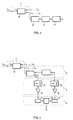
- a transmission line 1 of an optical network carrying data channels of different wavelengths ⁇ 1 ... ⁇ n has been shown. Further an optical signal processing block 2, an optical-electrical (O/E) converter (block 3) and an electrical signal processing block 4 are represented.
- O/E optical-electrical
- the output of block 4 is made available to the management system of the optical network in any way suitable for the purpose(not shown for reasons of clarity).
- a part of its optical power is coupled out from the said optical network in any way suitable for the purpose and an optical signal is derived therefrom for further processing.
- the said coupling out advantageously takes place via a power splitter means.
- an O/E converter (block 3) is applied.
- O/E converters are commercially available and will therefore not be described in detail. However, it will be appreciated that the quality of the O/E converter determines inter alia the maximum number of data channels to be monitored. So the requirements for the O/E converter increase with increasing number of data channels to monitor.
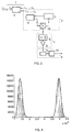
- Figs. 2 and 3 disclose advantageous embodiments of fig. 1. The same reference numerals as in fig. 1 are used.
- the power splitter means (block 5) is for example a 1 to 2-splitter (90/10).
- the signal which is coupled out is then split again, e.g. in a 1 to 2-splitter 6 (50/50) providing two sets of measurement data, said sets representing a first optical signal and a second optical signal respectively.
- Such splitters are commercially available and will therefore not be described in detail.
- the said second optical signal is obtained by passing the optical signal through a ⁇ -dependent attenuator 7.
- the ⁇ -dependent attenuator comprises two branches, the optical pathlength of the first branch being different from the optical pathlength of the second branch, and said branches having a common signal input and a common signal output.
- An advantageous example of such a B-dependent attenuator is a Mach-Zehnder interferometer known as such to those skilled in the art.
- the output signals of block 2 are passed to the O/E converter (block 3), comprising a photodiode 8 and optionally an amplifier 9 for each output from block 2.
- the output of block 3 is passed to the electrical signal processing block 4.
- the analogue measured O/E-converted data will have to be A/D converted first in any A/D converter 11 suitable for the purpose.
- the resolution of the A/D converter determines the accuracy of a measured probability density function of a data channel (will be explained below), and therefore inter alia the accuracy of estimated so-called Gaussian channel parameters (will be explained below), and also the maximum number of data channels to be monitored.
- a histogram which shows the frequency of a power level as function of the power level is obtained.
- the histogram is then normalised so that the surface beneath the curve equals 1, and then shows the probability density of the discrete power levels and has therefore become a probability density function. This is done for both sets of digital measurement data.
- So-called Gaussian channel parameters characterizing a data channel are extracted from these probability density functions. These Gaussian channel parameters are then evaluated to produce monitor information.
- the software to convert the discrete data into a probability density function, to estimate the Gaussian channel parameters, and to extract the monitor information can be programmed in any commercially available digital signal processing chip suitable for the purpose (block 12).
- Fig. 4 represents a probability density function of a single data channel.
- the vertical axis represents probability density, whereas the horizontal axis represents optical power in Watt (W).
- the solid line represents the estimated Gaussian probability density function.
- Fig. 5 represents a measured probability density function of two channels.
- the horizontal axis represents optical power in Watt (W), whereas the vertical axis represents the probability density.
- the solid line represents its approximated Gaussian model.
- the measured probability density function should contain four Gaussian peaks, however, in Fig. 5 only three peaks are visible.
- Fig. 6 represents a measured probability density function of three channels.
- the axes and the solid line represent data similar to those in fig. 5 Data channel statistics will now be explained in more detail.
- Each channel is characterized by a plurality of signal levels representing data.
- each channel is characterized by a plurality of levels of "1" and "0".
- PDF probability density function
- the PDF of a single data channel can be written as a sum of two Gaussian functions, one describing the '0' level of the data channel and the other the '1' level of the data channel. Assuming the probability of a '0' and '1' bit is the 1 ⁇ 2, the PDF a data channel can be described by four Gaussian parameters; the variance and mean of the '0' level, and the variance and mean of the '1' level. The mean and variance of each approximate Gaussian peak in the single data channel PDF corresponds to the average optical power and noise of a bit level of the data modulated on the data channel, respectively. It will be appreciated by those skilled in the art that more than two signal levels can be applied.
- the PDF of multiple data channels can be reconstructed from optimisation of the Gaussian parameters of individual data channels.
- the values for the means and variances in the measured PDF containing multiple data channels are a linear combination of the values for the means and variances of the Gaussian channel parameters.
- the use of a priori information about the Gaussian channel parameters will provide the necessary number of equations out of the measured PDF's to solve the parameters for the on-line Gaussian channel parameters of a plurality of data channels.
- Fig. 9 represents by way of non-limiting example a PDF processing diagram which can be applied in an advantageous manner by the present invention.
- the Gaussian channel parameters of the measured PDF's are extracted, using any suitable optimisation algorithm.
- Algorithms for the optimisation of parameters are known as such to those skilled in the art and will therefore not be described in detail. Examples of such algorithms are genetic algorithms, neural networks, and the like.
- the optical WDM network is configured in such a way that only the desired data channel is transmitted over the network (INIT). This is carried out at any frequency suitable for the purpose, e.g. once a day.
- the PDF of this channel is measured, then the Gaussian channel parameter and the attenuation of the ⁇ -dependent attenuator of this data channel are estimated.
- the estimated Gaussian channel parameters and attenuation of this channel are stored in a memory (MEM1). This process is repeated for all data channels.
- MEM1 memory
- the on-line PDF's containing multiple data channels are measured.
- the measured on-line PDF's PDF1 and PDF2 are advantageously processed by the algorithm.
- the algorithm generates randomly Gaussian channel parameters of the data channels, and these Gaussian channel parameters are used to reconstruct the PDF containing all data channels.
- the algorithm uses the correlation between estimated PDF and measured PDF to select the best estimates of the Gaussian channel parameters, these best estimates will be used to make new/better estimates of the Gaussian channel parameters of each data channel and this process will be repeated several times until a fairly good estimate of the Gaussian channel parameters of each data channel is found (block 13).
- This best estimate of this Gaussian channel parameter will be stored in a memory (MEM2).
- MEM4 a previously stored reference Gaussian channel parameter
- This comparison gives information about changes in the on-line Gaussian channel parameters. Changes in the Gaussian channel parameter may be reported in any way suitable for the purpose to the optical network management system for monitoring purposes (management purposes or network management purposes). In case of a large misfit the monitoring system is re-initialized via line B, whereas in case of a small misfit the Gaussian channel parameters are adjusted via line C.
- the measured Gaussian channel parameter will be stored (MEM3) and used as a priori information in the next measurement.
- the value for the correlation of the best Gaussian channel parameter does not approach a predetermined value, it means that the PDF model of the algorithm was not able to realize a satisfying fit, and this can be interpreted as a major deviation in the Gaussian channel parameter and in that case an alarm signal can be provided.
- Gaussian channel parameters can be extracted for an optical signal containing multiple data channels.
- the multiple channel PDF is related to the PDF of the individual data channels in the following way: wherein PDF 1,...,N represents the PDF of the plurality of N channels, and wherein N is a positive integer and PDF N represents the PDF of channel N.
- Eq. (3) is fitted to a measured PDF of a single data channel.
- a single channel PDF can be described by a finite number of parameters
- the multiple channel PDF can also be represented by a finite number of parameters.
- These parameters describe the signal quality of the individual data channels and are estimated using optimisation techniques, such as, as already disclosed in the foregoing, genetic algorithms, neural networks, Monte-Carlo methods, and the like.
- the theoretical model of the PDF is fitted to a measured two channel PDF.
- the peaks in the measured multiple channel PDF can also be approximated by Gaussian peaks with a mean and variance.
- a measured two channel PDF is presented.
- the means and variances belonging to the peaks in Fig. 5 are presented in Table 1: Values for the mean and variance of the Gaussian peaks in Fig. 5 Gaussian peak L I II III IV ⁇ L ( ⁇ W) 106 ? ? 332 ⁇ 2 L (pW 2 ) 48 ? ? 60
- the values for the mean and variance of the peaks in the multiple channel PDF are a linear combination of the values for the mean of the "0" and "1" bitlevel and variances of the individual data channel means values to a measured mean of a Gaussian peak in the multiple channel PDF.
- a priori information on the mean values of the individual data channel can be used to define the position and the solution range for the mean of a certain Gaussian peak in the multiple channel PDF (see Fig. 7) using its corresponding equation for the means of the individual data channel.
- the method provides two equations for the means and two equations for the variances, with eight Gaussian channel parameters to solve.
- the model of a PDF containing N data channels is a sum of 2 N Gaussian functions multiplied by the factor 1/2 N . Therefore the surface underneath the first peak in the model of the PDF should equal to 1/2 N . Thus calculating the surface beneath the first Gaussian peak in a measured PDF of an optical signal should provide information about the number of data channels present in that optical signal.
Landscapes
- Physics & Mathematics (AREA)
- Electromagnetism (AREA)
- Engineering & Computer Science (AREA)
- Computer Networks & Wireless Communication (AREA)
- Signal Processing (AREA)
- Optical Communication System (AREA)
- Monitoring And Testing Of Transmission In General (AREA)
Claims (14)
- Verfahren zum Überwachen eines optischen Netzwerkes, welches mit Wellenlängenmultiplex-Ausrüstung (WDM) ausgestattet ist und fähig ist, eine Vielzahl von Datenkanälen bei verschiedenen Wellenlängen zu übertragen, wobei das besagte Verfahren die Schritte umfasst:dadurch gekennzeichnet, dass Schritt c) die aufeinanderfolgenden Unterschritte umfasst:a) Auskoppeln eines Anteils seiner optischen Leistung aus dem besagten optischen Netzwerk an einem bestimmten Punkt in dem optischen Netzwerk,b) Verarbeiten des Anteiles von optischer Leistung, die in einer Anzahl von elektrischen Signalen resultiert,c) Analysieren der besagten Anzahl von elektrischen Signalen und Ableiten von Information über individuelle Datenkanäle, undd) Produzieren von Daten, die das Ergebnis des Schrittes c) darstellen,c1) Bestimmen aus der besagten Anzahl von elektrischen Signalen mindestens eine multiple Kanäle betreffende statistische Funktion von Interesse, die die besagte Vielzahl der Datenkanäle charakterisiert, undc2) Verarbeiten der besagten mindestens einen bestimmten Funktion von Interesse in einem vorbestimmten mathematischen Modell, um die besagte Information über die individuellen Datenkanäle abzuleiten.
- Verfahren nach Anspruch 1, dadurch gekennzeichnet, dass das besagte vorbestimmte mathematische Modell eine finite Anzahl von Parametern umfasst.
- Verfahren nach Anspruch 1 oder 2, dadurch gekennzeichnet, dass die besagte multiple Kanäle betreffende statistische Funktion eine Wahrscheinlichkeitsdichtefunktion ist.
- Verfahren nach Anspruch 3, dadurch gekennzeichnet, dass die Wahrscheinlichkeitsdichtefunktion eines einzelnen Datenkanals dargestellt ist durch eine Summe von zwei Gauss'schen Funktionen, die eine das "0"-Niveau des Datenkanals beschreibend und die andere das "1"-Niveau des besagten Datenkanals beschreibend.
- Verfahren nach einem der Ansprüche 1 bis 4, dadurch gekennzeichnet, dass der Schritt c2) mit dem Einsatz eines Optimierungsalgorithmus ausgeführt wird.
- Verfahren nach einem der Ansprüche 1 bis 5, dadurch gekennzeichnet, dass der Schritt b) umfasst:b1) Verarbeiten des besagten Anteils der optischen Leistung in solch einer Weise, dass mindestens zwei Sätze von optischen Messdaten erhalten werden, wobei die beiden Sätze jeweils ein erstes optisches verarbeitetes Signal und ein zweites optisches verarbeitetes Signal darstellen,b2) opto-elektronisches Erfassen der besagten zwei Sätze der optischen Messdaten, Wandeln der so erhaltenen Daten in eine digitale Form, Unterwerfen der Sätze von digitalen Messdaten einer statischen Analyse und Erhalten von Parametern, die für jeden Datenkanal charakteristisch sind.
- Verfahren nach Anspruch 6, dadurch gekennzeichnet, dass der Schritt b1) den Schritt des Aufspaltens der optischen Leistung, die in Schritt a) erhalten worden ist, umfasst.
- Verfahren nach Anspruch 6 oder sieben, dadurch gekennzeichnet, dass das besagte zweite optische Signal, welches in Schritt b1) erhalten worden ist, weiterhin durch eine λ-abhängige Dämpfung verarbeitet wird.
- Verfahren nach einem der vorstehenden Ansprüche 1 bis 8, dadurch gekennzeichnet, dass die in Schritt d) erzeugten Daten für Verwaltungszwecke oder Netzwerkverwaltungszwecke eingesetzt werden.
- Vorrichtung zum Überwachen eines optischen Netzwerkes, welches mit Wellenlängenmultiplex-Ausrüstung (WDM) (1) ausgestattet ist und fähig ist, eine Vielzahl von Datenkanälen bei verschiedenen Wellenlängen (λ1,..., λn) zu übertragen, wobei die besagte Vorrichtung umfasst:dadurch gekennzeichnet, dass die Analysemittel umfassen:Mittel (5) zum Auskoppeln eines Anteils seiner elektrischen Leistung aus dem besagten optischen Netzwerk,Mittel (2,3) zum Verarbeiten des besagten Anteiles von optischer Leistung, die in einer Anzahl von elektrischen Signalen resultiert,Mittel (4) zum Analysieren der besagten Anzahl von elektrischen Signalen und zum Ableiten von Information über individuelle Datenkanäle, undMittel (4) zum Erzeugen von Daten, die die besagte Information über die individuellen Datenkanäle darstellt,Mittel (11, 12; 13) zum Bestimmen aus der Anzahl von elektrischen Signalen von mindestens einer multiple Kanäle umfassenden statistischen Funktion von Interesse (PDF1, PDF2), welche die besagte Vielzahl von Datenkanälen charakterisiert, undMittel (12; 13) zum Verarbeiten der besagten mindestens einen bestimmten Funktion von Interesse in einem vorbestimmten mathematischen Modell, um die besagte Information über individuelle Datenkanäle abzuleiten.
- Vorrichtung nach Anspruch 10, dadurch gekennzeichnet, dass die besagte Vorrichtung weiterhin umfasst:Mittel (5) zum Ableiten eines optischen Signals aus den besagten Mitteln zum Auskoppeln aus dem besagten optischen Netzwerk eines Anteiles seiner optischen Leistung,Mittel (6) zum Verarbeiten dieses optischen Signals in solch einer Weise, dass mindestens zwei Sätze von optischen Messdaten erhalten werden, wobei die zwei Sätze jeweils ein erstes optisches verarbeitetes Signal und ein zweites optisches verarbeitetes Signal darstellen,Mittel (8) zum opto-elektronischen Erfassen der besagten zwei Sätze von optischen Messdaten,Mittel (11) zum Wandeln der so erhaltenen Daten in eine digitale Form,Mittel (12) zum Unterwerfen der Sätze von digitalen Messdaten einer statistischen Analyse, und zum Erhalten von Parametern, die jeden Datenkanal charakterisieren.
- Vorrichtung nach Anspruch 11, dadurch gekennzeichnet, dass die besagten Mittel zum Verarbeiten des besagten optischen Signals ein λ-abhängiges Dämpfungsglied (7) zur weiteren Verarbeitung des besagten zweiten optischen Signals umfassen.
- Vorrichtung nach Anspruch 12, dadurch gekennzeichnet, dass das λ-abhängige Dämpfungsglied zwei Arme umfasst, wobei die optische Pfadlänge des ersten Armes unterschiedlich ist von der optischen Pfadlänge des zweiten Armes, wobei die beiden Arme einen gemeinsamen Signaleingang und einen gemeinsamen Signalausgang aufweisen.
- Vorrichtung nach einem der vorstehenden Ansprüche 11 des 13, dadurch gekennzeichnet, dass die besagten Mittel zum Verarbeiten des besagten optischen Signals einen optischen Schalter (10) umfassen, dessen Ausgang mit dem Eingang der besagten Mittel zum opto-elektronischen Erfassen (8) der besagten zwei Sätze von optischen Messdaten verbunden ist.
Priority Applications (1)
| Application Number | Priority Date | Filing Date | Title |
|---|---|---|---|
| EP99948941A EP1123590B1 (de) | 1998-10-23 | 1999-09-24 | Verfahren und vorrichtung zur überwachung eines optischen wellenlängenmultiplexierten netzwerks |
Applications Claiming Priority (4)
| Application Number | Priority Date | Filing Date | Title |
|---|---|---|---|
| EP98203581 | 1998-10-23 | ||
| EP98203581A EP0996243A1 (de) | 1998-10-23 | 1998-10-23 | Verfahren und Vorrichtung zur Überwachung eines optischen Wellenlängenmultiplexierten Netzwerks |
| PCT/EP1999/007401 WO2000025451A1 (en) | 1998-10-23 | 1999-09-24 | Method and apparatus for monitoring an optical wdm network |
| EP99948941A EP1123590B1 (de) | 1998-10-23 | 1999-09-24 | Verfahren und vorrichtung zur überwachung eines optischen wellenlängenmultiplexierten netzwerks |
Publications (2)
| Publication Number | Publication Date |
|---|---|
| EP1123590A1 EP1123590A1 (de) | 2001-08-16 |
| EP1123590B1 true EP1123590B1 (de) | 2002-08-14 |
Family
ID=8234256
Family Applications (2)
| Application Number | Title | Priority Date | Filing Date |
|---|---|---|---|
| EP98203581A Withdrawn EP0996243A1 (de) | 1998-10-23 | 1998-10-23 | Verfahren und Vorrichtung zur Überwachung eines optischen Wellenlängenmultiplexierten Netzwerks |
| EP99948941A Expired - Lifetime EP1123590B1 (de) | 1998-10-23 | 1999-09-24 | Verfahren und vorrichtung zur überwachung eines optischen wellenlängenmultiplexierten netzwerks |
Family Applications Before (1)
| Application Number | Title | Priority Date | Filing Date |
|---|---|---|---|
| EP98203581A Withdrawn EP0996243A1 (de) | 1998-10-23 | 1998-10-23 | Verfahren und Vorrichtung zur Überwachung eines optischen Wellenlängenmultiplexierten Netzwerks |
Country Status (7)
| Country | Link |
|---|---|
| US (1) | US6714741B1 (de) |
| EP (2) | EP0996243A1 (de) |
| JP (1) | JP2003524919A (de) |
| AT (1) | ATE222433T1 (de) |
| AU (1) | AU6200499A (de) |
| DE (1) | DE69902552T2 (de) |
| WO (1) | WO2000025451A1 (de) |
Families Citing this family (9)
| Publication number | Priority date | Publication date | Assignee | Title |
|---|---|---|---|---|
| US7124181B1 (en) | 2001-06-29 | 2006-10-17 | Mcafee, Inc. | System, method and computer program product for improved efficiency in network assessment utilizing variable timeout values |
| US7035544B1 (en) | 2001-12-27 | 2006-04-25 | Mcafee, Inc. | Identification of related communications channels in a wavelength division multiplexed optical network |
| US7221869B1 (en) * | 2002-06-19 | 2007-05-22 | Alcatel Lucent | System and method for classifying high speed data signals utilizing low frequency electrical spectral characteristics |
| DE60208651T2 (de) * | 2002-11-15 | 2006-08-10 | Alcatel | Digitaler Signalverarbeitungsempfänger und Verfahren zu seinem Betrieb |
| US20060050751A1 (en) * | 2004-09-06 | 2006-03-09 | Fujitsu Limited | Optical transmission device for controlling optical level of wavelength multiplexed light and method thereof |
| US7623790B2 (en) * | 2005-09-24 | 2009-11-24 | Alcatel-Lucent Usa Inc. | Signal identification method |
| US7925156B2 (en) * | 2007-01-16 | 2011-04-12 | Broadlight, Ltd. | Apparatus and method for measuring the quality of burst signals and performing optical line diagnostics |
| JP7059699B2 (ja) * | 2018-03-08 | 2022-04-26 | 富士通株式会社 | パラメータ解析方法、パラメータ解析プログラム、及びパラメータ解析装置 |
| US11050487B2 (en) * | 2019-07-15 | 2021-06-29 | Huawei Technologies Co., Ltd. | Method and apparatus for laser frequency control |
Family Cites Families (7)
| Publication number | Priority date | Publication date | Assignee | Title |
|---|---|---|---|---|
| US5321541A (en) * | 1991-12-12 | 1994-06-14 | At&T Bell Laboratories | Passive optical communication network with broadband upgrade |
| CA2155693C (en) * | 1994-08-25 | 1999-12-14 | Daniel A. Fishman | Performance monitoring and fault location in optical transmission systems |
| JPH0964819A (ja) * | 1995-08-23 | 1997-03-07 | Fujitsu Ltd | 光システム |
| JP2748908B2 (ja) * | 1995-10-19 | 1998-05-13 | 日本電気株式会社 | 光伝送路特性測定方法とその装置および光波長多重伝送方法とその装置 |
| US5793909A (en) * | 1996-09-09 | 1998-08-11 | Lucent Technologies Inc. | Optical monitoring and test access module |
| US6215565B1 (en) * | 1998-07-27 | 2001-04-10 | Mci Communications Corporation | Method of and system for diagnosing optical system failures |
| US6532087B1 (en) * | 1998-07-29 | 2003-03-11 | Ciena Corporation | Multiple signal Q-tester |
-
1998
- 1998-10-23 EP EP98203581A patent/EP0996243A1/de not_active Withdrawn
-
1999
- 1999-09-24 EP EP99948941A patent/EP1123590B1/de not_active Expired - Lifetime
- 1999-09-24 AT AT99948941T patent/ATE222433T1/de not_active IP Right Cessation
- 1999-09-24 WO PCT/EP1999/007401 patent/WO2000025451A1/en not_active Ceased
- 1999-09-24 JP JP2000578933A patent/JP2003524919A/ja active Pending
- 1999-09-24 US US09/807,870 patent/US6714741B1/en not_active Expired - Fee Related
- 1999-09-24 AU AU62004/99A patent/AU6200499A/en not_active Abandoned
- 1999-09-24 DE DE69902552T patent/DE69902552T2/de not_active Expired - Lifetime
Also Published As
| Publication number | Publication date |
|---|---|
| ATE222433T1 (de) | 2002-08-15 |
| US6714741B1 (en) | 2004-03-30 |
| WO2000025451A1 (en) | 2000-05-04 |
| DE69902552D1 (de) | 2002-09-19 |
| AU6200499A (en) | 2000-05-15 |
| JP2003524919A (ja) | 2003-08-19 |
| EP0996243A1 (de) | 2000-04-26 |
| DE69902552T2 (de) | 2003-04-24 |
| EP1123590A1 (de) | 2001-08-16 |
Similar Documents
| Publication | Publication Date | Title |
|---|---|---|
| US7756369B2 (en) | OSNR monitoring apparatus and method using polarization splitting | |
| DE69834999T2 (de) | Qualitätsüberwachungssystem von optischen Signalen mit verschiedenen Bitraten | |
| DE69736856T2 (de) | Überwachung von nichtlinearen Effekten in einem optischen Übertragungssystem | |
| DE69804759T2 (de) | Verfahren und gerät für zeitbereichsreflektometrie (otdr) | |
| CN102244538B (zh) | 分支光纤检测系统及方法、光分配网络和分光器 | |
| EP3113390B1 (de) | Vorrichtung und verfahren zur überwachung optischer leistungsparameter und optisches übertragungssystem | |
| Wang et al. | Machine learning-based multifunctional optical spectrum analysis technique | |
| CN104079347B (zh) | 一种光信噪比测量方法 | |
| US6714741B1 (en) | Method and apparatus for monitoring an optical WDM network | |
| DE10001388B4 (de) | AWG-(Arrayed Waveguide Grating)-Modul und Vorrichtung zur Überwachung eines Lichtsignals, die dieses verwendet | |
| DE60213726T2 (de) | Verfahren und Vorrichtung zur Bestimmung des Ursprungs des Qualitätsverlustes von optischen Signalen | |
| US11290190B2 (en) | Method and apparatus for automatic signal gain setting | |
| EP1685663B1 (de) | Optisches flash-leistungsüberwachungsgerät | |
| CN114696897B (zh) | 光信噪比监测方法及装置 | |
| US7969561B2 (en) | Apparatus and method for monitoring extinction ratio of optical signals | |
| DE60208312T2 (de) | Fehlerratenmessungsverfahren in einem optischen Übertragungssystem und Vorrichtung zur Ausführung des Verfahrens | |
| Isaeva et al. | Measuring of Optical Signal to Noise Ratio in High-Speed Coherent Channels of Optical Transmission Systems | |
| DE69520008T2 (de) | Vorrichtung zum Abfragen eines Lichtwellenleiternetzwerks | |
| Shi et al. | Regression assisted experimental validation for estimating distributed PDL in optical links | |
| CN117692061A (zh) | 一种实时监测装置及一种密集波分传输系统 | |
| EP1936841A2 (de) | OSNR-Überwachungsgerät und Verfahren mittels Verwendung von Polarisationsteilung | |
| EP1058978B1 (de) | Messung der signalqualität in digitalen optischen glasfaserübertragungsnetzen durch auswertung des signalhistogramms | |
| DE60124650T2 (de) | Verfahren und System zur optischen Überlagerungsdetektion eines optischen Signals | |
| US6707547B2 (en) | Method and apparatus for analyzing wavelength-division multiplexed signal light | |
| Fabrega et al. | Cost-efficient Non-intrusive Performance Monitoring in Optical Networks Using Polarization-Diverse Spectrum Analysis |
Legal Events
| Date | Code | Title | Description |
|---|---|---|---|
| PUAI | Public reference made under article 153(3) epc to a published international application that has entered the european phase |
Free format text: ORIGINAL CODE: 0009012 |
|
| 17P | Request for examination filed |
Effective date: 20010523 |
|
| AK | Designated contracting states |
Kind code of ref document: A1 Designated state(s): AT BE CH CY DE DK ES FI FR GB GR IE IT LI LU MC NL PT SE |
|
| AX | Request for extension of the european patent |
Free format text: AL;LT;LV;MK;RO;SI |
|
| D17P | Request for examination filed (deleted) | ||
| R17P | Request for examination filed (corrected) |
Effective date: 20010523 |
|
| GRAG | Despatch of communication of intention to grant |
Free format text: ORIGINAL CODE: EPIDOS AGRA |
|
| GRAG | Despatch of communication of intention to grant |
Free format text: ORIGINAL CODE: EPIDOS AGRA |
|
| GRAH | Despatch of communication of intention to grant a patent |
Free format text: ORIGINAL CODE: EPIDOS IGRA |
|
| 17Q | First examination report despatched |
Effective date: 20020130 |
|
| GRAH | Despatch of communication of intention to grant a patent |
Free format text: ORIGINAL CODE: EPIDOS IGRA |
|
| GRAA | (expected) grant |
Free format text: ORIGINAL CODE: 0009210 |
|
| AK | Designated contracting states |
Kind code of ref document: B1 Designated state(s): AT BE CH CY DE DK ES FI FR GB GR IE IT LI LU MC NL PT SE |
|
| PG25 | Lapsed in a contracting state [announced via postgrant information from national office to epo] |
Ref country code: IT Free format text: LAPSE BECAUSE OF FAILURE TO SUBMIT A TRANSLATION OF THE DESCRIPTION OR TO PAY THE FEE WITHIN THE PRESCRIBED TIME-LIMIT;WARNING: LAPSES OF ITALIAN PATENTS WITH EFFECTIVE DATE BEFORE 2007 MAY HAVE OCCURRED AT ANY TIME BEFORE 2007. THE CORRECT EFFECTIVE DATE MAY BE DIFFERENT FROM THE ONE RECORDED. Effective date: 20020814 Ref country code: GR Free format text: LAPSE BECAUSE OF FAILURE TO SUBMIT A TRANSLATION OF THE DESCRIPTION OR TO PAY THE FEE WITHIN THE PRESCRIBED TIME-LIMIT Effective date: 20020814 Ref country code: FI Free format text: LAPSE BECAUSE OF FAILURE TO SUBMIT A TRANSLATION OF THE DESCRIPTION OR TO PAY THE FEE WITHIN THE PRESCRIBED TIME-LIMIT Effective date: 20020814 Ref country code: AT Free format text: LAPSE BECAUSE OF FAILURE TO SUBMIT A TRANSLATION OF THE DESCRIPTION OR TO PAY THE FEE WITHIN THE PRESCRIBED TIME-LIMIT Effective date: 20020814 |
|
| REF | Corresponds to: |
Ref document number: 222433 Country of ref document: AT Date of ref document: 20020815 Kind code of ref document: T |
|
| REG | Reference to a national code |
Ref country code: GB Ref legal event code: FG4D |
|
| REG | Reference to a national code |
Ref country code: CH Ref legal event code: EP |
|
| REG | Reference to a national code |
Ref country code: CH Ref legal event code: NV Representative=s name: ISLER & PEDRAZZINI AG |
|
| REG | Reference to a national code |
Ref country code: IE Ref legal event code: FG4D |
|
| REF | Corresponds to: |
Ref document number: 69902552 Country of ref document: DE Date of ref document: 20020919 |
|
| PG25 | Lapsed in a contracting state [announced via postgrant information from national office to epo] |
Ref country code: IE Free format text: LAPSE BECAUSE OF NON-PAYMENT OF DUE FEES Effective date: 20020924 |
|
| PG25 | Lapsed in a contracting state [announced via postgrant information from national office to epo] |
Ref country code: CY Free format text: LAPSE BECAUSE OF FAILURE TO SUBMIT A TRANSLATION OF THE DESCRIPTION OR TO PAY THE FEE WITHIN THE PRESCRIBED TIME-LIMIT Effective date: 20020930 |
|
| PG25 | Lapsed in a contracting state [announced via postgrant information from national office to epo] |
Ref country code: SE Free format text: LAPSE BECAUSE OF FAILURE TO SUBMIT A TRANSLATION OF THE DESCRIPTION OR TO PAY THE FEE WITHIN THE PRESCRIBED TIME-LIMIT Effective date: 20021114 Ref country code: DK Free format text: LAPSE BECAUSE OF FAILURE TO SUBMIT A TRANSLATION OF THE DESCRIPTION OR TO PAY THE FEE WITHIN THE PRESCRIBED TIME-LIMIT Effective date: 20021114 |
|
| PG25 | Lapsed in a contracting state [announced via postgrant information from national office to epo] |
Ref country code: PT Free format text: LAPSE BECAUSE OF FAILURE TO SUBMIT A TRANSLATION OF THE DESCRIPTION OR TO PAY THE FEE WITHIN THE PRESCRIBED TIME-LIMIT Effective date: 20021202 |
|
| ET | Fr: translation filed | ||
| PG25 | Lapsed in a contracting state [announced via postgrant information from national office to epo] |
Ref country code: ES Free format text: LAPSE BECAUSE OF FAILURE TO SUBMIT A TRANSLATION OF THE DESCRIPTION OR TO PAY THE FEE WITHIN THE PRESCRIBED TIME-LIMIT Effective date: 20030228 |
|
| PG25 | Lapsed in a contracting state [announced via postgrant information from national office to epo] |
Ref country code: MC Free format text: LAPSE BECAUSE OF NON-PAYMENT OF DUE FEES Effective date: 20030401 |
|
| PLBE | No opposition filed within time limit |
Free format text: ORIGINAL CODE: 0009261 |
|
| STAA | Information on the status of an ep patent application or granted ep patent |
Free format text: STATUS: NO OPPOSITION FILED WITHIN TIME LIMIT |
|
| REG | Reference to a national code |
Ref country code: IE Ref legal event code: MM4A |
|
| 26N | No opposition filed |
Effective date: 20030515 |
|
| PGFP | Annual fee paid to national office [announced via postgrant information from national office to epo] |
Ref country code: LU Payment date: 20040910 Year of fee payment: 6 |
|
| PGFP | Annual fee paid to national office [announced via postgrant information from national office to epo] |
Ref country code: BE Payment date: 20040930 Year of fee payment: 6 |
|
| PG25 | Lapsed in a contracting state [announced via postgrant information from national office to epo] |
Ref country code: LU Free format text: LAPSE BECAUSE OF NON-PAYMENT OF DUE FEES Effective date: 20050930 Ref country code: BE Free format text: LAPSE BECAUSE OF NON-PAYMENT OF DUE FEES Effective date: 20050930 |
|
| REG | Reference to a national code |
Ref country code: CH Ref legal event code: PCAR Free format text: ISLER & PEDRAZZINI AG;POSTFACH 1772;8027 ZUERICH (CH) |
|
| BERE | Be: lapsed |
Owner name: KONINKLIJKE *KPN N.V. Effective date: 20050930 |
|
| PGFP | Annual fee paid to national office [announced via postgrant information from national office to epo] |
Ref country code: NL Payment date: 20090915 Year of fee payment: 11 Ref country code: GB Payment date: 20090922 Year of fee payment: 11 Ref country code: CH Payment date: 20090923 Year of fee payment: 11 |
|
| PGFP | Annual fee paid to national office [announced via postgrant information from national office to epo] |
Ref country code: DE Payment date: 20090922 Year of fee payment: 11 |
|
| REG | Reference to a national code |
Ref country code: NL Ref legal event code: V1 Effective date: 20110401 |
|
| REG | Reference to a national code |
Ref country code: CH Ref legal event code: PL |
|
| GBPC | Gb: european patent ceased through non-payment of renewal fee |
Effective date: 20100924 |
|
| REG | Reference to a national code |
Ref country code: FR Ref legal event code: ST Effective date: 20110531 |
|
| REG | Reference to a national code |
Ref country code: DE Ref legal event code: R119 Ref document number: 69902552 Country of ref document: DE Effective date: 20110401 |
|
| PG25 | Lapsed in a contracting state [announced via postgrant information from national office to epo] |
Ref country code: FR Free format text: LAPSE BECAUSE OF NON-PAYMENT OF DUE FEES Effective date: 20100930 Ref country code: CH Free format text: LAPSE BECAUSE OF NON-PAYMENT OF DUE FEES Effective date: 20100930 Ref country code: DE Free format text: LAPSE BECAUSE OF NON-PAYMENT OF DUE FEES Effective date: 20110401 Ref country code: LI Free format text: LAPSE BECAUSE OF NON-PAYMENT OF DUE FEES Effective date: 20100930 |
|
| PG25 | Lapsed in a contracting state [announced via postgrant information from national office to epo] |
Ref country code: NL Free format text: LAPSE BECAUSE OF NON-PAYMENT OF DUE FEES Effective date: 20110401 Ref country code: GB Free format text: LAPSE BECAUSE OF NON-PAYMENT OF DUE FEES Effective date: 20100924 |
|
| PGFP | Annual fee paid to national office [announced via postgrant information from national office to epo] |
Ref country code: FR Payment date: 20091001 Year of fee payment: 11 |