EP1123614B1 - Architecture de reseau pour reseaux de communication ou de donnees - Google Patents
Architecture de reseau pour reseaux de communication ou de donnees Download PDFInfo
- Publication number
- EP1123614B1 EP1123614B1 EP99957856A EP99957856A EP1123614B1 EP 1123614 B1 EP1123614 B1 EP 1123614B1 EP 99957856 A EP99957856 A EP 99957856A EP 99957856 A EP99957856 A EP 99957856A EP 1123614 B1 EP1123614 B1 EP 1123614B1
- Authority
- EP
- European Patent Office
- Prior art keywords
- network
- service
- networks
- physical
- services
- Prior art date
- Legal status (The legal status is an assumption and is not a legal conclusion. Google has not performed a legal analysis and makes no representation as to the accuracy of the status listed.)
- Expired - Lifetime
Links
- 238000004891 communication Methods 0.000 title claims abstract description 18
- 230000006870 function Effects 0.000 claims description 36
- 230000010354 integration Effects 0.000 claims description 9
- 238000000034 method Methods 0.000 claims description 9
- 238000012545 processing Methods 0.000 abstract description 11
- 230000011664 signaling Effects 0.000 description 12
- 238000007726 management method Methods 0.000 description 9
- 108091006146 Channels Proteins 0.000 description 4
- 230000005540 biological transmission Effects 0.000 description 3
- 238000012544 monitoring process Methods 0.000 description 3
- 238000013523 data management Methods 0.000 description 2
- 230000001419 dependent effect Effects 0.000 description 2
- 238000011161 development Methods 0.000 description 2
- 230000018109 developmental process Effects 0.000 description 2
- 230000003993 interaction Effects 0.000 description 2
- 230000008569 process Effects 0.000 description 2
- 101000874387 Astacus leptodactylus Sarcoplasmic calcium-binding protein 1 Proteins 0.000 description 1
- 238000013459 approach Methods 0.000 description 1
- 239000000969 carrier Substances 0.000 description 1
- 230000008859 change Effects 0.000 description 1
- 238000006243 chemical reaction Methods 0.000 description 1
- 238000005516 engineering process Methods 0.000 description 1
- 238000012423 maintenance Methods 0.000 description 1
- 238000005259 measurement Methods 0.000 description 1
- 238000010295 mobile communication Methods 0.000 description 1
- 230000008520 organization Effects 0.000 description 1
- 230000000704 physical effect Effects 0.000 description 1
- 230000009467 reduction Effects 0.000 description 1
- 238000000926 separation method Methods 0.000 description 1
- 230000003068 static effect Effects 0.000 description 1
- 238000012360 testing method Methods 0.000 description 1
- 230000007704 transition Effects 0.000 description 1
Images



Classifications
-
- H—ELECTRICITY
- H04—ELECTRIC COMMUNICATION TECHNIQUE
- H04Q—SELECTING
- H04Q3/00—Selecting arrangements
- H04Q3/0016—Arrangements providing connection between exchanges
- H04Q3/0029—Provisions for intelligent networking
- H04Q3/0045—Provisions for intelligent networking involving hybrid, i.e. a mixture of public and private, or multi-vendor systems
-
- H—ELECTRICITY
- H04—ELECTRIC COMMUNICATION TECHNIQUE
- H04L—TRANSMISSION OF DIGITAL INFORMATION, e.g. TELEGRAPHIC COMMUNICATION
- H04L12/00—Data switching networks
- H04L12/64—Hybrid switching systems
- H04L12/6418—Hybrid transport
-
- H—ELECTRICITY
- H04—ELECTRIC COMMUNICATION TECHNIQUE
- H04Q—SELECTING
- H04Q3/00—Selecting arrangements
- H04Q3/0016—Arrangements providing connection between exchanges
- H04Q3/0029—Provisions for intelligent networking
- H04Q3/0054—Service creation techniques
Definitions
- the invention relates to a network architecture for various communication and / or data networks for the provision of value-added services for users.
- These communication and data networks can have different physical properties. They can differ in how they access the network functions provided and the principles of data transmission (eg the transmission protocols used and the corresponding standards). Furthermore, they offer various services for the user of the network.
- a physical network is understood below to mean a conventional data or communication network, such as the circuit-switched fixed network (based on SS # 7, central channel signaling system no. 7), the mobile radio network or a computer network such as the Internet or even a local area network LAN, based on a Communication protocol such as TCP / IP or Token Ring.
- the providers of the basic network functions are referred to below as network operators.
- a corporate network refers to a data or communication network or else a network of several such networks, which is assigned to an organizational unit. It enables communication within this organization and is shielded externally by technical means.
- Network operators and service providers provide the network users with basic functions and services of the physical networks (basic services).
- So-called value-added services can be generated by integrating basic services (usually) of a network. These value-added services can then be sold directly to the user by the service provider (or even special service integrators, who in turn use basic services of the service providers).
- value-added services are implemented in addition to the basic services in addition to the conventional voice or data transmission by a so-called intelligent network.
- value-added services are, for example, a unique telephone number for a user throughout the network (Universal Personal Number), toll-free telephone numbers (Freephone) or voice-over-the-telephone (televoting).
- SSP service switching point
- SCP service control point
- the network elements responsible for the services prove to be a bottleneck when network utilization is high, since all service queries run over these network elements and must be processed there. For larger, well-utilized networks, this requires a correspondingly high investment in high-performance hardware, in particular for the centrally controlling network elements ("bottleneck”), since only this can handle the traffic volume with acceptable delay times.
- a failure of a single such network node here means the unavailability of all value-added services of the entire network.
- the different networks are physically separated.
- a customer In order to be able to use the services of the networks, a customer must switch between different service providers, which in individual cases can also result in the change of the terminal.
- the purpose of the invention is to provide a way in which the existing physical networks, including their basic services, can be provided uniformly, while avoiding the abovementioned disadvantages. It should also be able to integrate value-added services, as a combination of basic services offered in different physical networks.
- a new, distributed network architecture is introduced, in the form of a layer of network elements between the already existing physical networks and the service providers or users. These network elements communicate via interfaces with each other, as well as with them connected physical networks.
- This layer which is realized by network elements distributed in the network, allows the user of the network (also the service provider) access to the network resources present in the physical, underlying networks. All existing basic and value-added services can be used (transparency).
- the required and generated data access, billing, traffic measurements Certainly are collected separately according to the users or service providers in the respective physical networks, managed and made available for further processing.
- network elements of the extended architecture can provide special services for controlling the networks, in particular central services such as naming, trading or security functions. This provision can be done either separately, in separate network elements, or in the network elements that also provide the general services.
- this architecture is characterized by a much higher reliability, availability and fault tolerance.
- the network elements are interconnected by available data networks such as the Internet. Required information is exchanged over this network. The cooperation and the exchange of information is controlled by a distributed network operating system, which resides in the individual network elements. It is ensured by the two-sided transaction principle that changes are carried out safely.
- a network element (client) for this purpose passes calls of network functions to executing network elements (servers).
- the interfaces to underlying physical networks are standardized.
- the interaction of the individual network elements is significantly simplified, a technical coordination of service providers, network operators and the additional service integrators can be omitted.
- the integration of new physical networks, network elements or basic and value-added services is so easily possible.
- standardized function calls are made available on the surface to the physical networks. This reduces the effort in implementing services.
- a functional class is a logical summary of several function calls that serve a specific purpose. Examples of this are 'Connection Management', 'Port Management', 'Quality of Service Management' or 'Event Monitoring'.
- This principle can be applied not only to individual physical networks or network elements, but also to the functions and services implemented in these network elements.
- An essential embodiment of the invention involves the distribution of the network functions in the network elements. By a high redundancy of the functions on the one hand, a high reliability is achieved. This is also achieved by selecting the network node handling the call. A load distribution in the network can be realized thereby.
- the defined amount of 'basic functions' is not static, but can be changed and expanded at any time.
- customers can use value-added services, integrated from different networks, while always ensuring correct billing to the different network operators and service providers.
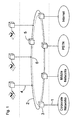
- the FIG. 1 schematically shows a distributed network architecture, which manifests itself in 3 layers.
- the middle layer now shows the distributed network architecture that is established 'over' the physical networks.
- the individual physical networks are in each case connected via at least one connection (1) and a suitable interface in a network element (3) to a data network (2).
- connection (1) and a suitable interface in a network element (3) to a data network (2).
- data network (2) is the service integration.
- the representation of the data network as a ring is only one possibility, the structure of the data network is for the invention is not important.
- the top layer contains the network elements of the service providers. These are also connected via suitable interfaces (4) to the data network. This information required for this purpose (for authentication of users, billing, administration of services, etc.) are exchanged. This can also be done in a standardized form, which ensures a significant simplification of the communication also different service providers and service integrators.
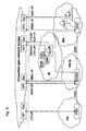
- FIG. 2 In order to specify the example explained above, in FIG. 2 based on a more specific configuration.
- a user obtains a value-added service from a service provider, which consists of a landline (PSTN, 7b) and a mobile service (Mobile Networks, 7a).
- PSTN public switched telephone network
- 7b mobile service
- the basic services are provided by two different network operators (7a, 7b). These services are offered to him jointly by a service provider (8) who stores and manages the customer profile in his customer care center (ABC, Administration, Billing, Customer Care Center) and settles the sold services with the customer.
- ABSC Administration, Billing, Customer Care Center
- the service provider forwards the relevant information of the customer profile, such as customer ID, service profile, for the receipt of the respective service from the service provider to the service integrator via an interface 4 (realized, for example, by an API, application programming interface), which in turn forwards the respective sub-profile for the fixed network and mobile communications service via interfaces (1a, 1b to the network operator and receives information required therefrom via the same interface, such as the established fixed network number and mobile phone number.
- customer profile such as customer ID, service profile
- an interface 4 realized, for example, by an API, application programming interface
- the service integrator uses a network element (5) to control the corresponding network elements (3a, 3b) connected to the physical networks of the network operators, which operate the appropriate interfaces (1a, 1b) of the respective physical network (see also FIG. 4 ).
- a suitable network element (3 or 5) of the service integrator receives this feedback, evaluates it and determines further required network elements (3a or 3b) based on the value-added service requested by the service provider and forwards the required information via the connecting network (2) to the network elements involved ( 3a, 3b) on.
- the service integrator confirms the complete release of the service for a customer ID via the interface (4) to the service provider who notifies the customer of This release is notified via the interface (8).
- the value-added service can be used by the customer.
- Usage-dependent information that is determined on the basis of the use of the basic services in the network elements of the network operator, are first transmitted via the interface (1a, 1b) forwarded to the service integrator.
- this information is collected in accordance with the integrated value-added services made available to the service provider, provided with a code (user ID, service ID) and forwarded to the customer care center (ABC) via (4) ,
- the service provider is now able to assign the received information to the respective customer profile, evaluate and settle (8).
- FIG. 3 shows a section of the new architecture, which is the parent of the physical networks.
- An API manager residing in one of the network elements routes network function calls to the executing network elements (server nodes).
- the API Manager provides the necessary routing information network-wide. This information is exchanged between the network elements and kept consistent.
- Network-wide distributed resources can be used in this way.
- a load sharing is possible by the same functions can be addressed in several network elements.
- the example shown in the figure contains an application call of a value-added service which contains function calls for a plurality of subfunctions (x, y, z).
- the first addressed network element can not process the function call because it does not contain the required functions or its capacity is already fully utilized.
- Network element (SN2) handles the processing of functional part (x), network element (SN3) the processing of (y) and network element (SN4) the processing of (z).
- the routing of the individual partial function calls to the processing network elements can be controlled by various criteria.
- the existence of the required function and the utilization of the individual network elements were specified here.
- Another criterion in the distributed network may be the length of the path to the processing node, other criteria are conceivable.
- FIG. 4 describes in detail the interface between a physical network (PSTN) and a network element in the new distributed network architecture.
- PSTN physical network
- the interface component is geared to the specific requirements of the respective underlying basic network. It is structured in such a way that it receives the function calls for a group of system-independent function classes via the interface (2) and converts them into system-specific commands and procedures of the network elements in the physical network.
- the interface of the (API) to the bottom is accordingly dependent on the underlying physical network. Examples of usable protocols for communication are MML (Man Machine Language), CCS # 7 (Signaling System No. 7), INAP (Intelligent Network Application Part) or DSS1 (Digital Subscriber Signaling System No. 1, EURO ISDN signaling), depending on the physical network.
- the interface of the (API) to 'top' is uniformly defined.
- the defined functional classes may include, for example, connection management, port management, event monitoring and quality of service management.
- This principle of the disclosed, standardized interfaces simplifies the cooperation of the network operators with the service providers and integrators, in particular with the introduction of new physical networks and the interaction of the different physical networks.
- the interface to the physical network does not have to consist of just one network node (dashed line).
- FIG. 5 shows a possible structure from the point of view of the physical networks.
- EWSD Digital Telephone Switching Center
- PSTN fixed network
- MSC Mobile Services Switching Center
- SS # 7 central channel signaling system no. 7
- CN corporate network
- PBX private exchange
- EURO ISDN signaling DSS1, Digital Subscriber Signaling System No. 1
- CTI interface CTI-I / F, Computer Telephony Integration
- a fixed network is essentially constructed by telephone exchanges.
- the interface can be realized here in various ways, for example through an INAP protocol interface (INAP-I / F, Intelligent Network Application Part) or a Man Machine Language Interface (MML I / F).
- INAP protocol interface I / F
- MML I / F Man Machine Language Interface
- MML Man Machine Language
- MSC mobile radio network
- the Service Control Point represents the central node computer, which evaluates and processes the service and function calls. So far, this node computer is also the central interface to other physical networks, such as the fixed network (PSTN) or mobile network (MN).
- PSTN fixed network
- MN mobile network
- a possible interface to this central network node is a private SCP interface (private SCP-I / F).
- the IN network architecture is also considered a basic network.
- the Service Management Point is responsible for the introduction, provisioning and maintenance of value-added services.
- the development of new services including testing is carried out in the Service Creation Environment (SCE).
- the Customer Service Center (CSC) maintains and updates the customer data.
- An interface to the CSC is the (CSC-I / F service).
- the mobile network manages its customer data in a Home Location Register (HLR) and a Visitor Location Register (VLR).
- HLR Home Location Register
- VLR Visitor Location Register
- EWSD fixed network
- I intelligent network
- MSC switching computer
- Another interface is provided by means of an INAP-like protocol Mobile Application Part (MAP).
- MAP Mobile Application Part
- FIG. 6 shows again an exemplary network, which is a division of services and resources in 3 layers.
- MN physical networks
- CN Internet
- SCN data network according to the invention
Landscapes
- Engineering & Computer Science (AREA)
- Computer Networks & Wireless Communication (AREA)
- Signal Processing (AREA)
- Mobile Radio Communication Systems (AREA)
- Telephonic Communication Services (AREA)
Abstract
Claims (7)
- Procédé de mise à disposition d'un service de télécommunications à valeur ajoutée pour des utilisateurs du service par le biais d'un intégrateur de services (3, 5) composé des éléments suivantes :- des services de base d'au moins un premier fournisseur de services (7a) d'un premier réseau physique de télécommunications et- des services de base d'un deuxième fournisseur de services (7b) d'un deuxième réseau de télécommunications,- l'intégrateur de services (3, 5) gérant un profil de services pour un usager et- ce profil de services contenant un premier profil partiel pour le premier réseau physique de télécommunications et un deuxième profil partiel pour un deuxième réseau physique de télécommunications,- l'intégrateur de services (3, 5) retransmettant les deux profils partiels aux exploitants de réseau respectifs des premier et deuxième réseaux physiques de télécommunications et- l'intégrateur de services (3, 5) exécutant un service à valeur ajoutée demandé dès que les services de base requis pour exécuter le service à valeur ajoutée sont débloqués pour l'intégrateur de services (3, 5) par les réseaux physiques de télécommunications associés.
- Procédé selon la revendication 1, caractérisé en ce que la communication entre l'intégrateur de services (3, 5) et le fournisseur de services se fait selon le principe de transaction.
- Procédé selon l'une des revendications 1 ou 2, caractérisé en ce que le décompte des services utilisés avec l'usager est effectué par un centre de suivi clients (ABC) de l'intégrateur de services (3, 5).
- Architecture de réseau pour réseaux de communication et/ou de données permettant d'exécuter le procédé selon la revendication 1, l'architecture de réseau comportant :- deux réseaux physiques de télécommunication ;- une architecture de réseau distribuée avec plusieurs éléments de réseau (3, 5), au moins quelques-uns des éléments de réseau (3, 5) étant prévus aux fins de la communication et de la coopération avec respectivement un réseau physique et- au moins un fournisseur de services (8) qui est couplé à l'architecture de réseau distribuée via une interface (4) indépendante de système via une surface logique uniforme.
- Architecture de réseau selon la revendication 4, caractérisée en ce que la commande de fonctions de réseau des différents réseaux physiques est prise en charge par un système d'exploitation distribué (6).
- Architecture de réseau selon l'une des revendications précédentes 4 à 5, caractérisée en ce que l'intégration dynamique de nouveaux éléments de réseau (3, 5) est rendue possible par le fait que le nouvel élément de réseau (3, 5) effectue un enregistrement auprès d'un autre élément de réseau approprié (3, 5), lequel enregistre ces informations et les redistribue à d'autres éléments de réseau (3, 5).
- Architecture de réseau selon l'une des revendications précédentes 4 à 6, caractérisée en ce que l'intégration dynamique de nouvelles interfaces (1a, 1b, 4) d'éléments de réseau déjà existants (3a, 3b, 4) est rendue possible par le fait qu'un élément de réseau (3a, 3b, 4) effectue un enregistrement des nouvelles fonctions auprès d'un autre élément de réseau approprié, lequel enregistre ces informations et les redistribue à d'autres éléments de réseau supplémentaires.
Applications Claiming Priority (3)
| Application Number | Priority Date | Filing Date | Title |
|---|---|---|---|
| DE19848114 | 1998-10-19 | ||
| DE19848114 | 1998-10-19 | ||
| PCT/DE1999/003207 WO2000024174A1 (fr) | 1998-10-19 | 1999-10-05 | Architecture de reseau pour reseaux de communication ou de donnees |
Publications (2)
| Publication Number | Publication Date |
|---|---|
| EP1123614A1 EP1123614A1 (fr) | 2001-08-16 |
| EP1123614B1 true EP1123614B1 (fr) | 2011-03-09 |
Family
ID=7884920
Family Applications (1)
| Application Number | Title | Priority Date | Filing Date |
|---|---|---|---|
| EP99957856A Expired - Lifetime EP1123614B1 (fr) | 1998-10-19 | 1999-10-05 | Architecture de reseau pour reseaux de communication ou de donnees |
Country Status (5)
| Country | Link |
|---|---|
| US (1) | US7010618B1 (fr) |
| EP (1) | EP1123614B1 (fr) |
| DE (1) | DE59915257D1 (fr) |
| ES (1) | ES2362565T3 (fr) |
| WO (1) | WO2000024174A1 (fr) |
Families Citing this family (3)
| Publication number | Priority date | Publication date | Assignee | Title |
|---|---|---|---|---|
| WO2001049057A1 (fr) * | 1999-12-23 | 2001-07-05 | Markport Limited | Itinerance a prepaiement dans des reseaux de telecommunication mobile |
| EP1396157A1 (fr) * | 2001-06-13 | 2004-03-10 | Siemens Aktiengesellschaft | Interfaces de programmation pour un central telephonique |
| AU2003264213A1 (en) * | 2003-09-17 | 2005-04-06 | Petr Hejl | Method for a accessing users through a network |
Family Cites Families (12)
| Publication number | Priority date | Publication date | Assignee | Title |
|---|---|---|---|---|
| US5187787B1 (en) | 1989-07-27 | 1996-05-07 | Teknekron Software Systems Inc | Apparatus and method for providing decoupling of data exchange details for providing high performance communication between software processes |
| US5317568A (en) * | 1991-04-11 | 1994-05-31 | Galileo International Partnership | Method and apparatus for managing and facilitating communications in a distributed hetergeneous network |
| US5329619A (en) | 1992-10-30 | 1994-07-12 | Software Ag | Cooperative processing interface and communication broker for heterogeneous computing environments |
| IL111154A0 (en) | 1993-10-21 | 1994-12-29 | Martino Ii John A | Systems and methods for electronic messaging |
| KR100346342B1 (ko) * | 1994-04-01 | 2002-11-22 | 텔레폰아크티에볼라게트 엘엠 에릭슨 | 전기통신망에서의이동성 |
| DE4438522C2 (de) * | 1994-10-31 | 1997-08-21 | Ibm | Einrichtung zur Übertragung von Datenströmen in Datenkommunikationsnetzen |
| US5781857A (en) * | 1996-06-28 | 1998-07-14 | Motorola, Inc. | Method of establishing an email monitor responsive to a wireless communications system user |
| US5944795A (en) * | 1996-07-12 | 1999-08-31 | At&T Corp. | Client-server architecture using internet and guaranteed quality of service networks for accessing distributed media sources |
| US6651104B1 (en) * | 1996-11-12 | 2003-11-18 | Ericsson Inc. | Multi-layered interface for interconnecting application programs to system bus lines for electronic devices |
| US6151628A (en) * | 1997-07-03 | 2000-11-21 | 3Com Corporation | Network access methods, including direct wireless to internet access |
| US6680922B1 (en) * | 1998-07-10 | 2004-01-20 | Malibu Networks, Inc. | Method for the recognition and operation of virtual private networks (VPNs) over a wireless point to multi-point (PtMP) transmission system |
| US6760601B1 (en) * | 1999-11-29 | 2004-07-06 | Nokia Corporation | Apparatus for providing information services to a telecommunication device user |
-
1999
- 1999-10-05 EP EP99957856A patent/EP1123614B1/fr not_active Expired - Lifetime
- 1999-10-05 ES ES99957856T patent/ES2362565T3/es not_active Expired - Lifetime
- 1999-10-05 WO PCT/DE1999/003207 patent/WO2000024174A1/fr not_active Ceased
- 1999-10-05 US US09/807,889 patent/US7010618B1/en not_active Expired - Lifetime
- 1999-10-05 DE DE59915257T patent/DE59915257D1/de not_active Expired - Lifetime
Non-Patent Citations (1)
| Title |
|---|
| None * |
Also Published As
| Publication number | Publication date |
|---|---|
| WO2000024174A1 (fr) | 2000-04-27 |
| DE59915257D1 (de) | 2011-04-21 |
| EP1123614A1 (fr) | 2001-08-16 |
| ES2362565T3 (es) | 2011-07-07 |
| US7010618B1 (en) | 2006-03-07 |
Similar Documents
| Publication | Publication Date | Title |
|---|---|---|
| DE69529589T2 (de) | Intelligente schnurlose Signalisierungsschicht für Telekommunikationsnetz | |
| DE69932088T2 (de) | Verfahren und mittel zum bereitstellen von diensten in einem telekommunikationsnetz | |
| DE69332632T2 (de) | Anrufverarbeitungssystem | |
| DE69927867T2 (de) | System zum Integrieren von privaten Kommunikationsendgeräten | |
| EP1123622B1 (fr) | Procede de commande d'elements reseau | |
| DE69835920T2 (de) | Verfahren zur Verkehrsvermittlung in einem verbesserten intelligenten Netzwerk | |
| EP0657083B1 (fr) | Systeme de coordination de demandes de connexion | |
| DE69920912T2 (de) | Telekommunikationssystem zum bereitstellen von in- und nicht-in-diensten | |
| WO2002015547A1 (fr) | Repartition des appels en cas de centraux d'appel repartis | |
| EP0817509B1 (fr) | Procédé pour la construction des connexions de communication automatique, et unité de réglement de service | |
| DE69910570T2 (de) | Programmierung von anrufverarbeitungsanwendungen in einem vermittlungssystem | |
| EP0878972B1 (fr) | Réseau de raccordement d'abonnés, central de commutation, dispositif de commande de service et procédé d'établissemnt des communications | |
| EP1123614A1 (fr) | Architecture de reseau pour reseaux de communication ou de donnees | |
| EP1064764B1 (fr) | Dispositif et procede permettant de traiter des demandes de communication dans des reseaux de communication heterogenes | |
| DE69921431T2 (de) | Gateway in einem intelligenten Netz | |
| EP0951186A2 (fr) | Méthode dans un réseau de communication pour le routage de messages vers des terminaux de communication et dispositif pour mettre en oeuvre la méthode | |
| EP1407621B1 (fr) | Dispositif de transmission de messages de signalisation | |
| EP1517528B1 (fr) | Distribution d'appels entre des centres d'appel | |
| EP1289335A2 (fr) | Méthode et dispositif pour la commande de charge de ressources de commutation | |
| EP0957645B1 (fr) | Elément de réseau pour un réseau de télécommunication intelligent | |
| DE19854831A1 (de) | Verfahren zum Bereitstellen von Diensten, Infrastrukturverwalter und Dienststeuerplattform | |
| DE10023624A1 (de) | Dienst-Einheit | |
| EP0967776A2 (fr) | Methode d'etablissement d'une connection, unite de commande de service et reseau de communication | |
| EP1034666A1 (fr) | Procede et dispositif pour echanger des donnees orientees specifiquement utilisation dans un reseau intelligent | |
| EP1587331B1 (fr) | Central de télécommunication, combinaison de centraux de télécommunication, procédé de configuration et procédé d'exploitation d'une telle combinaison, ainsi que du logiciel d'identification d'un client et d'un central dans celle-ci |
Legal Events
| Date | Code | Title | Description |
|---|---|---|---|
| PUAI | Public reference made under article 153(3) epc to a published international application that has entered the european phase |
Free format text: ORIGINAL CODE: 0009012 |
|
| 17P | Request for examination filed |
Effective date: 20010223 |
|
| AK | Designated contracting states |
Kind code of ref document: A1 Designated state(s): AT BE CH CY DE DK ES FI FR GB GR IE IT LI LU MC NL PT SE |
|
| 17Q | First examination report despatched |
Effective date: 20030825 |
|
| RBV | Designated contracting states (corrected) |
Designated state(s): DE ES FR GB IT |
|
| 17Q | First examination report despatched |
Effective date: 20030825 |
|
| RAP1 | Party data changed (applicant data changed or rights of an application transferred) |
Owner name: NOKIA SIEMENS NETWORKS GMBH & CO. KG |
|
| RAP3 | Party data changed (applicant data changed or rights of an application transferred) |
Owner name: NOKIA SIEMENS NETWORKS S.P.A. |
|
| RAP3 | Party data changed (applicant data changed or rights of an application transferred) |
Owner name: NOKIA SIEMENS NETWORKS GMBH & CO. KG |
|
| GRAP | Despatch of communication of intention to grant a patent |
Free format text: ORIGINAL CODE: EPIDOSNIGR1 |
|
| GRAS | Grant fee paid |
Free format text: ORIGINAL CODE: EPIDOSNIGR3 |
|
| GRAA | (expected) grant |
Free format text: ORIGINAL CODE: 0009210 |
|
| AK | Designated contracting states |
Kind code of ref document: B1 Designated state(s): DE ES FR GB IT |
|
| REG | Reference to a national code |
Ref country code: GB Ref legal event code: FG4D Free format text: NOT ENGLISH |
|
| REF | Corresponds to: |
Ref document number: 59915257 Country of ref document: DE Date of ref document: 20110421 Kind code of ref document: P |
|
| REG | Reference to a national code |
Ref country code: DE Ref legal event code: R096 Ref document number: 59915257 Country of ref document: DE Effective date: 20110421 |
|
| REG | Reference to a national code |
Ref country code: ES Ref legal event code: FG2A Ref document number: 2362565 Country of ref document: ES Kind code of ref document: T3 Effective date: 20110707 |
|
| PLBE | No opposition filed within time limit |
Free format text: ORIGINAL CODE: 0009261 |
|
| STAA | Information on the status of an ep patent application or granted ep patent |
Free format text: STATUS: NO OPPOSITION FILED WITHIN TIME LIMIT |
|
| 26N | No opposition filed |
Effective date: 20111212 |
|
| REG | Reference to a national code |
Ref country code: DE Ref legal event code: R097 Ref document number: 59915257 Country of ref document: DE Effective date: 20111212 |
|
| PGFP | Annual fee paid to national office [announced via postgrant information from national office to epo] |
Ref country code: ES Payment date: 20121026 Year of fee payment: 14 Ref country code: IT Payment date: 20121026 Year of fee payment: 14 |
|
| PG25 | Lapsed in a contracting state [announced via postgrant information from national office to epo] |
Ref country code: IT Free format text: LAPSE BECAUSE OF NON-PAYMENT OF DUE FEES Effective date: 20131005 |
|
| REG | Reference to a national code |
Ref country code: DE Ref legal event code: R081 Ref document number: 59915257 Country of ref document: DE Owner name: NOKIA SOLUTIONS AND NETWORKS GMBH & CO. KG, DE Free format text: FORMER OWNER: SIEMENS AKTIENGESELLSCHAFT, 80333 MUENCHEN, DE Effective date: 20110210 Ref country code: DE Ref legal event code: R081 Ref document number: 59915257 Country of ref document: DE Owner name: NOKIA SOLUTIONS AND NETWORKS GMBH & CO. KG, DE Free format text: FORMER OWNER: NOKIA SIEMENS NETWORKS GMBH & CO. KG, 81541 MUENCHEN, DE Effective date: 20140731 |
|
| REG | Reference to a national code |
Ref country code: ES Ref legal event code: FD2A Effective date: 20141107 |
|
| REG | Reference to a national code |
Ref country code: ES Ref legal event code: PC2A Owner name: NOKIA SOLUTIONS AND NETWORKS GMBH & CO.KG Effective date: 20141121 |
|
| PG25 | Lapsed in a contracting state [announced via postgrant information from national office to epo] |
Ref country code: ES Free format text: LAPSE BECAUSE OF NON-PAYMENT OF DUE FEES Effective date: 20131006 |
|
| REG | Reference to a national code |
Ref country code: FR Ref legal event code: CD Owner name: NOKIA SOLUTIONS AND NETWORKS GMBH & CO.KG, DE Effective date: 20150211 |
|
| REG | Reference to a national code |
Ref country code: FR Ref legal event code: PLFP Year of fee payment: 17 |
|
| REG | Reference to a national code |
Ref country code: FR Ref legal event code: PLFP Year of fee payment: 18 |
|
| REG | Reference to a national code |
Ref country code: FR Ref legal event code: PLFP Year of fee payment: 19 |
|
| PGFP | Annual fee paid to national office [announced via postgrant information from national office to epo] |
Ref country code: FR Payment date: 20171024 Year of fee payment: 19 Ref country code: DE Payment date: 20171019 Year of fee payment: 19 |
|
| PGFP | Annual fee paid to national office [announced via postgrant information from national office to epo] |
Ref country code: GB Payment date: 20171019 Year of fee payment: 19 |
|
| REG | Reference to a national code |
Ref country code: GB Ref legal event code: 732E Free format text: REGISTERED BETWEEN 20190207 AND 20190213 |
|
| REG | Reference to a national code |
Ref country code: DE Ref legal event code: R081 Ref document number: 59915257 Country of ref document: DE Owner name: PROVENANCE ASSET GROUP LLC, PITTSFORD, US Free format text: FORMER OWNER: NOKIA SOLUTIONS AND NETWORKS GMBH & CO. KG, 81541 MUENCHEN, DE |
|
| REG | Reference to a national code |
Ref country code: DE Ref legal event code: R119 Ref document number: 59915257 Country of ref document: DE |
|
| GBPC | Gb: european patent ceased through non-payment of renewal fee |
Effective date: 20181005 |
|
| PG25 | Lapsed in a contracting state [announced via postgrant information from national office to epo] |
Ref country code: DE Free format text: LAPSE BECAUSE OF NON-PAYMENT OF DUE FEES Effective date: 20190501 |
|
| PG25 | Lapsed in a contracting state [announced via postgrant information from national office to epo] |
Ref country code: FR Free format text: LAPSE BECAUSE OF NON-PAYMENT OF DUE FEES Effective date: 20181031 |
|
| PG25 | Lapsed in a contracting state [announced via postgrant information from national office to epo] |
Ref country code: GB Free format text: LAPSE BECAUSE OF NON-PAYMENT OF DUE FEES Effective date: 20181005 |