EP1123619B1 - Anordnung zur hochauflösenden abtastung grosser bildformate - Google Patents
Anordnung zur hochauflösenden abtastung grosser bildformate Download PDFInfo
- Publication number
- EP1123619B1 EP1123619B1 EP99947561A EP99947561A EP1123619B1 EP 1123619 B1 EP1123619 B1 EP 1123619B1 EP 99947561 A EP99947561 A EP 99947561A EP 99947561 A EP99947561 A EP 99947561A EP 1123619 B1 EP1123619 B1 EP 1123619B1
- Authority
- EP
- European Patent Office
- Prior art keywords
- light
- document
- strip
- image plane
- plane
- Prior art date
- Legal status (The legal status is an assumption and is not a legal conclusion. Google has not performed a legal analysis and makes no representation as to the accuracy of the status listed.)
- Expired - Lifetime
Links
Images

Classifications
-
- H—ELECTRICITY
- H04—ELECTRIC COMMUNICATION TECHNIQUE
- H04N—PICTORIAL COMMUNICATION, e.g. TELEVISION
- H04N1/00—Scanning, transmission or reproduction of documents or the like, e.g. facsimile transmission; Details thereof
- H04N1/024—Details of scanning heads ; Means for illuminating the original
- H04N1/028—Details of scanning heads ; Means for illuminating the original for picture information pick-up
- H04N1/02815—Means for illuminating the original, not specific to a particular type of pick-up head
- H04N1/02845—Means for illuminating the original, not specific to a particular type of pick-up head using an elongated light source, e.g. tubular lamp, LED array
- H04N1/0285—Means for illuminating the original, not specific to a particular type of pick-up head using an elongated light source, e.g. tubular lamp, LED array in combination with at least one reflector which is in fixed relation to the light source
-
- H—ELECTRICITY
- H04—ELECTRIC COMMUNICATION TECHNIQUE
- H04N—PICTORIAL COMMUNICATION, e.g. TELEVISION
- H04N1/00—Scanning, transmission or reproduction of documents or the like, e.g. facsimile transmission; Details thereof
- H04N1/024—Details of scanning heads ; Means for illuminating the original
- H04N1/028—Details of scanning heads ; Means for illuminating the original for picture information pick-up
- H04N1/02815—Means for illuminating the original, not specific to a particular type of pick-up head
- H04N1/02845—Means for illuminating the original, not specific to a particular type of pick-up head using an elongated light source, e.g. tubular lamp, LED array
- H04N1/0287—Means for illuminating the original, not specific to a particular type of pick-up head using an elongated light source, e.g. tubular lamp, LED array using a tubular lamp or a combination of such lamps
-
- H—ELECTRICITY
- H04—ELECTRIC COMMUNICATION TECHNIQUE
- H04N—PICTORIAL COMMUNICATION, e.g. TELEVISION
- H04N1/00—Scanning, transmission or reproduction of documents or the like, e.g. facsimile transmission; Details thereof
- H04N1/04—Scanning arrangements, i.e. arrangements for the displacement of active reading or reproducing elements relative to the original or reproducing medium, or vice versa
- H04N1/10—Scanning arrangements, i.e. arrangements for the displacement of active reading or reproducing elements relative to the original or reproducing medium, or vice versa using flat picture-bearing surfaces
- H04N1/1013—Scanning arrangements, i.e. arrangements for the displacement of active reading or reproducing elements relative to the original or reproducing medium, or vice versa using flat picture-bearing surfaces with sub-scanning by translatory movement of at least a part of the main-scanning components
-
- H—ELECTRICITY
- H04—ELECTRIC COMMUNICATION TECHNIQUE
- H04N—PICTORIAL COMMUNICATION, e.g. TELEVISION
- H04N1/00—Scanning, transmission or reproduction of documents or the like, e.g. facsimile transmission; Details thereof
- H04N1/04—Scanning arrangements, i.e. arrangements for the displacement of active reading or reproducing elements relative to the original or reproducing medium, or vice versa
- H04N1/10—Scanning arrangements, i.e. arrangements for the displacement of active reading or reproducing elements relative to the original or reproducing medium, or vice versa using flat picture-bearing surfaces
- H04N1/1013—Scanning arrangements, i.e. arrangements for the displacement of active reading or reproducing elements relative to the original or reproducing medium, or vice versa using flat picture-bearing surfaces with sub-scanning by translatory movement of at least a part of the main-scanning components
- H04N1/1039—Movement of the main scanning components
- H04N1/1043—Movement of the main scanning components of a sensor array
-
- H—ELECTRICITY
- H04—ELECTRIC COMMUNICATION TECHNIQUE
- H04N—PICTORIAL COMMUNICATION, e.g. TELEVISION
- H04N1/00—Scanning, transmission or reproduction of documents or the like, e.g. facsimile transmission; Details thereof
- H04N1/04—Scanning arrangements, i.e. arrangements for the displacement of active reading or reproducing elements relative to the original or reproducing medium, or vice versa
- H04N1/19—Scanning arrangements, i.e. arrangements for the displacement of active reading or reproducing elements relative to the original or reproducing medium, or vice versa using multi-element arrays
- H04N1/191—Scanning arrangements, i.e. arrangements for the displacement of active reading or reproducing elements relative to the original or reproducing medium, or vice versa using multi-element arrays the array comprising a one-dimensional [1D] array
- H04N1/192—Simultaneously or substantially simultaneously scanning picture elements on one main scanning line
- H04N1/193—Simultaneously or substantially simultaneously scanning picture elements on one main scanning line using electrically scanned linear arrays, e.g. linear CCD arrays
-
- H—ELECTRICITY
- H04—ELECTRIC COMMUNICATION TECHNIQUE
- H04N—PICTORIAL COMMUNICATION, e.g. TELEVISION
- H04N2201/00—Indexing scheme relating to scanning, transmission or reproduction of documents or the like, and to details thereof
- H04N2201/04—Scanning arrangements
- H04N2201/0402—Arrangements not specific to a particular one of the scanning methods covered by groups H04N1/04 - H04N1/207
- H04N2201/0436—Scanning a picture-bearing surface lying face up on a support
Definitions
- the present invention relates to the very high-resolution digitization of large documents (or flat objects with low relief), for their digital computer storage for archiving, consultation, reproduction, dissemination or subsequent processing.
- a solution for scanning documents larger than the A0 size is to photograph the document by means of a large format camera and to digitize the silver image thus obtained by a digitizer of photographs.
- the invention is thus particularly suitable for the digitization of documentary collections of paper documents of both large and very large size and in very large numbers with a very high resolution, such as ancient cartographic documentary collections of which it is desired to produce a digitized version. .
- the invention is applicable to the reproduction of paper documents in bad condition, retouched corrected, repaired, or the reproduction of thick documents or flat objects with low relief, or fragile documents or objects, to the extent that the reproduction, as we shall see, takes place without physical contact with the document or object to be reproduced.
- a high resolution requires significant illumination of the document or the object to be digitized if one wants to obtain the desired quality in a reasonable time.
- US-A-4,910,601 , US-A-4,256,959 and US-A-4,459,618 describe document scanning devices where a thin light strip scans the document and a motorized mirror system forms an image of the illuminated area on a fixed sensor.
- the document US-A-4,667,255 discloses an image scanning apparatus with a moving equipment behind a shooting objective, and carrying both a linear sensor and a light source moved concurrently by the movement of the moving equipment.
- This "through-the-lens" (TTL) illumination of the object is thereby mechanically centered on the area analyzed by the sensor at a given moment.
- the preamble of claim 1 corresponds to the general structure disclosed by the US-A-4,667,255 above, and the characterizing part sets out the elements of the invention which make it possible to obtain the desired result.
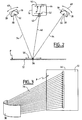
- This device 10 is intended to reproduce a document (or, in general, a flat object having a low relief) referenced 12 which, in this configuration, is placed on a table 14 surmounted by a camera 16 mounted on a 18.
- Light generators 20 which will be described in more detail below (here four in number) are arranged on either side of the document 12 and are fixed to the table 14 by arms 22 and articulated and motorized connections 24.
- the assembly is controlled by a computer workstation 26 which ensures the coordinated control of the various elements and the recovery of the digitized data.
- the illustrated configuration figure 1 which is the one typically corresponding to a reproduction bench, is not limiting and can be adapted according to the size and nature of the documents to be reproduced.
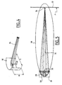
- the light generators 20 comprise, as illustrated Figures 2 to 5 a linear light source 28, for example the filament of a tubular bulb.
- a linear light source 28 for example the filament of a tubular bulb.
- This source is associated to a reflector 30 in the form of an elliptical cylinder portion whose director is parallel to the linear filament of the source 28 and whose generator is an ellipse, one of which is located on the linear filament of the source 28.
- a frontal cup 32 in the form of a portion of a cylinder of revolution, intended to fold towards the reflector 30 rays that would have escaped the main mirror and redirect to the latter, in order to increase the efficiency of the system.
- the light generator 20 produces a light beam 34 producing, on the plane P (object plane on which is placed the document 12 to be reproduced) a narrow straight light band 36, the position of the plane P being chosen to be at the other focus of the ellipse 38 ( figure 5 ).
- the elliptical shape of the reflector 30 thus causes the concentration of the light rays coming from one of the focal points (the light source 28) on the other focus (the light band 36) situated on the plane to be illuminated P.
- the mirror is formed of an elliptical cylinder portion, it has no curvature parallel to the direction of the generator, so that no focusing occurs along this axis and the result is a thin line of light on the plane of the document to enter.
- a point or, at least, filamentous light source 28 associated with an elliptical optical quality.
- various types of lamps providing such a pointy or filiform emissive pattern such as halogen, xenon, etc. lamps.
- Xenon lamps have an extremely small emissive field, but they are of a delicate use and, especially quite expensive considering the necessary apparatus.
- linear filament halogen lamps are much easier to use and benefit from greater diffusion due to their general public applications.
- Their filaments are spiraled or coiled, so that the effective luminous diameter is of the order of 2 mm, which, taking into account the optics used described above, produces on the object plane a light strip of 5 to 8 year wide.
- the light generator 20 thus constituted is in the form of a parallelepiped block, one of whose large faces faces the surface to be illuminated.
- these light generators are preferably used, for example two groups of two projectors, as illustrated.
- the analysis chamber 16 placed above the document 12 receives the light rays 40 corresponding to the illuminated band 36, and forms, by means of a suitable objective 42, an image of the object plane P on an image plane P '.
- This image plane P ' is analyzed by a photosensitive sensor DTC ( Charge-Coupled Device CCD) 44 in the form of a strip arranged parallel to the central axis of the illuminated strip 36 and homothetically to the latter.
- DTC Charge-Coupled Device CCD
- the photosensitive sensor 44 which analyzes a line of the image plane P ', is scanned regularly in a direction perpendicular to the direction of the strip, allowing it to cover the entire image plane.
- This scanning shown schematically by the arrows 46, is for example operated by a stepper motor of high precision, typically a motor controlled at 50800 steps / revolution with ball screw transmission with preload and play catch.
- This technique allows to obtain a mechanical precision of 1 ⁇ m, perfectly compatible with the necessary precision to obtain the desired resolution, of the order of 6 ⁇ m, on the image plane P '(corresponding to about 0.1 mm on the object plane P for a document 1300 ⁇ 2167 mm).
- the displacement of the photosensitive sensor 44 on the image plane P ' is synchronized with the displacement of the light strip 36 on the object plane P.
- the displacement of this light strip is operated by a motorization of the light generators 20, shown schematically by the arrows 48 on the figure 2 .
- the invention uses an electronic control system, the position of the sensor being known at any time by the engine control software, this information is used as a basis of calculation for controlling the orientation motors of light generators.
- the analysis line (corresponding to the width, perpendicular to the direction of the bar, of a pixel of the sensor 44) is extremely fine. The continuation of such a line of analysis by the lighting device would be very difficult if the light strip 36 was too narrow. However, except to use reflectors of very large size, the width of the light band remains of the order of a few centimeters, that is to say dozens of times greater than what would be strictly necessary.
- a filter 52 inside the chamber 16, in the path of the light beam, by repeating the scanning three times for a YMC trichromatic input ( yellow, magenta, cyan) or RGB (red, green, blue), the filter being changed between each scan, all automatically under the control of the control software.
- the number of passes can be increased if a finer color analysis is useful or necessary, for example six successive passages with insertion of the filters R, V, B, Y, M and C, in this order or in a different order , for a hexachromic analysis.
Landscapes
- Engineering & Computer Science (AREA)
- Multimedia (AREA)
- Signal Processing (AREA)
- Facsimile Scanning Arrangements (AREA)
- Liquid Developers In Electrophotography (AREA)
- Facsimile Heads (AREA)
- Image Input (AREA)
- Mechanical Optical Scanning Systems (AREA)
- Transforming Light Signals Into Electric Signals (AREA)
Claims (2)
- Vorrichtung (10) zum Digitalisieren von Dokumenten, aufweisend:• eine ebene Auflage (14), die eine Objektebene (P) bestimmt und die geeignet ist ein Dokument (12) aufzunehmen;• eine Analysekammer (16) die abgesetzt vom Dokument angeordnet ist, die ein Objekiv (42) umfasst, das ein Bild des Dokuments auf einer Bildebene (P') der Analysekammer (16) erzeugt, und einen beweglichen photosensiblen Sensor (44) umfasst, der eine Bildzeile in einer ersten Richtung analysiert,• wobei die Kammer erste Antriebsmittel aufweist, die geeignet sind den Sensor auf kontrollierte Weise in einer zweiten Richtung, die sich von der ersten Richtung unterscheidet, fortzubewegen (46) in der Art, dass die Oberfläche der Bildebene in dieser zweiten Richtung überstrichen wird und die geeignet sind eine momentane Positionsinformation des beweglichen Sensors auf der Bildebene zu liefern,• Beleuchtungsmittel, die geeignet sind auf der ebenen Auflage einen schmalen, leuchtenden Streifen (36) zu erzeugen, der parallel zu der ersten Richtung orientiert ist, wobei dieser Streifen auf kontrollierte Weise fortbewegt wird in der Art, dass die Oberfläche der ebenen Auflage parallel zu der zweiten Richtung auf mit der Fortbewegung des beweglichen Sensors synchronisierte Weise überstrichen wird,wobei eine Homothetie zwischen der Analysezeile des beweglichen Sensors auf der Bildebene einerseits und dem leuchtenden Streifen auf der Objektebene andererseits beibehalten wird,
dadurch charakterisiert, dass:• die Beleuchtungsmittel zwei Projektoren (50) oder zwei Gruppen an Projektoren (50) aufweisen, die auf der einen und der anderen Seite der ebenen Auflage in einer Konfigurierung angeordnet sind, die entsprechend der Größe und der Art der zu digitalisierenden Dokumente anpassbar ist,• wobei jeder der Projektoren ein ausrichtbarer, motorisierter Projektor ist, der zweite Antriebsmittel aufweist, die sich von den ersten Antriebsmitteln unterscheiden, wobei die zweiten Antriebsmittel geeignet sind, die Ausrichtung des entsprechenden Projektors in der Art zu steuern, dass der von den zwei Projektoren oder Gruppen an Projektoren erzeugte leuchtende Streifen die Oberfläche der Objektebene parallel zu der zweiten Richtung überstreicht,• die Vorrichtung umfasst außerdem Synchronisationsmittel, die geeignet sind, die zweiten Antriebsmittel gemäß den ersten Antriebsmitteln zu regeln, wobei die Synchronisationsmittel elektronische Mittel zur Verfolgung der Analysezeile über den leuchtenden Streifen sind, die Mittel aufweisen zum:• Verwenden der Positionsinformation als Berechnungsbasis, um die zweiten Antriebsmittel der entsprechenden Projektoren in Abhängigkeit der Positionsinformation auf entsprechende Weise zu steuern, die Homothetie zwischen der Analysezeile des beweglichen Sensors auf der Bildebene einerseits und dem leuchtenden Streifen auf der Objektebene andererseits beibehaltend. - Vorrichtung nach Anspruch 1, in welcher jeder der Projektoren (20) eine lineare Leuchtquelle (28) und einen Reflektor (30) in der Form eines elliptischen Zylinderabschnittes aufweist, wobei dieser Zylinder durch eine zur linearen Leuchtquelle parallele Direktrix und durch eine elliptische Generatrix, deren einer Brennpunkt auf der linearen Leuchtquelle liegt und deren anderer Brennpunkt auf der Objektebene liegt, bestimmt ist.
Applications Claiming Priority (3)
| Application Number | Priority Date | Filing Date | Title |
|---|---|---|---|
| FR9813291A FR2785130B1 (fr) | 1998-10-23 | 1998-10-23 | Dispositif de numerisation a haute resolution de documents de grandes dimensions |
| FR9813291 | 1998-10-23 | ||
| PCT/FR1999/002472 WO2000025509A1 (fr) | 1998-10-23 | 1999-10-13 | Dispositif de numerisation a haute resolution de documents de grandes dimensions |
Publications (2)
| Publication Number | Publication Date |
|---|---|
| EP1123619A1 EP1123619A1 (de) | 2001-08-16 |
| EP1123619B1 true EP1123619B1 (de) | 2009-09-30 |
Family
ID=9531899
Family Applications (1)
| Application Number | Title | Priority Date | Filing Date |
|---|---|---|---|
| EP99947561A Expired - Lifetime EP1123619B1 (de) | 1998-10-23 | 1999-10-13 | Anordnung zur hochauflösenden abtastung grosser bildformate |
Country Status (7)
| Country | Link |
|---|---|
| US (1) | US6603582B1 (de) |
| EP (1) | EP1123619B1 (de) |
| AT (1) | ATE444647T1 (de) |
| AU (1) | AU6096299A (de) |
| DE (1) | DE69941486D1 (de) |
| FR (1) | FR2785130B1 (de) |
| WO (1) | WO2000025509A1 (de) |
Families Citing this family (10)
| Publication number | Priority date | Publication date | Assignee | Title |
|---|---|---|---|---|
| US6965460B1 (en) * | 2000-08-08 | 2005-11-15 | Hewlett-Packard Development Company, L.P. | Method and system for scanning an image using a look-down linear array scanner |
| JP2003078717A (ja) * | 2001-08-31 | 2003-03-14 | Brother Ind Ltd | 凹凸物の撮像装置、撮像用照明装置及び撮像方法 |
| US20050002069A1 (en) * | 2001-11-23 | 2005-01-06 | Markus Schnitzlein | Device and method for scanning an original copy involving a lifting and rotational movement of a camera |
| JP2004136585A (ja) * | 2002-10-18 | 2004-05-13 | Web Tec Kk | 印刷物品質検査装置 |
| FR2871325B1 (fr) * | 2004-06-07 | 2006-09-15 | Lumiere Technology Sa | Scanner multispectral a etendue chromatique ou gamut elargi, notamment scanner a plat monopasse |
| JP4471401B1 (ja) * | 2008-12-05 | 2010-06-02 | パナソニック株式会社 | 帳票読取り装置および帳票検出方法 |
| JP4883101B2 (ja) * | 2009-02-02 | 2012-02-22 | ブラザー工業株式会社 | 画像読取装置 |
| USD740826S1 (en) * | 2012-06-14 | 2015-10-13 | Pfu Limited | Scanner |
| USD709890S1 (en) * | 2012-06-14 | 2014-07-29 | Pfu Limited | Scanner |
| JP2023179002A (ja) * | 2022-06-07 | 2023-12-19 | 富士フイルムビジネスイノベーション株式会社 | 読取装置および画像形成装置 |
Family Cites Families (19)
| Publication number | Priority date | Publication date | Assignee | Title |
|---|---|---|---|---|
| DE68431C (de) * | A. ROSCHER in Chemnitz, Lutherstr. 24 | Bandwebstuhl mit abgestufter Uebersetzung zwischen Antriebwelle und Schaftexcenter | ||
| US4459618A (en) * | 1979-09-12 | 1984-07-10 | The Mead Corporation | Line source illuminator |
| US4256959A (en) * | 1979-09-12 | 1981-03-17 | The Mead Corporation | Optical scanner including feedback for reflector control |
| US4667255A (en) * | 1979-09-24 | 1987-05-19 | Datacopy Corporation | Electronic camera employing a solid-state image sensor |
| US4422100A (en) * | 1982-03-08 | 1983-12-20 | The Mead Corporation | Document scanning apparatus |
| US4767927A (en) * | 1984-08-16 | 1988-08-30 | Kabushiki Kaisha Toshiba | Apparatus for reading radiation image information stored in imaging plate |
| JPS6198342A (ja) * | 1984-10-19 | 1986-05-16 | Fuji Photo Film Co Ltd | 放射線画像情報記録読取装置 |
| US4835386A (en) * | 1985-10-18 | 1989-05-30 | Fuji Photo Film Co., Ltd. | Radiation image recording and read-out apparatus |
| US4873708A (en) * | 1987-05-11 | 1989-10-10 | General Electric Company | Digital radiographic imaging system and method therefor |
| US4910601A (en) * | 1987-09-08 | 1990-03-20 | Truvel Corporation | Digitizing scanning apparatus |
| JP3063099B2 (ja) * | 1989-09-29 | 2000-07-12 | ミノルタ株式会社 | 原稿読み取り装置 |
| US5747825A (en) * | 1992-11-20 | 1998-05-05 | Picker International, Inc. | Shadowgraphic x-ray imager with TDI camera and photo stimulable phosphor plate |
| US5430289A (en) * | 1993-12-22 | 1995-07-04 | Hewlett-Packard Company | Illuminating scanner lid for an optical scanner |
| US5625183A (en) * | 1994-06-15 | 1997-04-29 | Nec Corporation | Rotary mirror scanner unit having optical angular displacement sensor |
| US5516094A (en) * | 1994-06-24 | 1996-05-14 | Xerox Corporation | Linear array sensor for copy sheet registration |
| JPH08154154A (ja) * | 1994-09-29 | 1996-06-11 | Minolta Co Ltd | 画像読み取り装置 |
| DE69629235T2 (de) * | 1995-05-05 | 2004-05-27 | Hewlett-Packard Co. (N.D.Ges.D.Staates Delaware), Palo Alto | Gerät zur automatischen Detektion der Anwesenheit, der Breite und der Phasenverschiebung eines Dokumentes innerhalb eines Dokumentenabtasters |
| US5805272A (en) * | 1995-11-24 | 1998-09-08 | Minolta Co., Ltd. | Image reading apparatus for book-like document or the like |
| JPH09149207A (ja) * | 1995-11-24 | 1997-06-06 | Minolta Co Ltd | 画像読取装置 |
-
1998
- 1998-10-23 FR FR9813291A patent/FR2785130B1/fr not_active Expired - Fee Related
-
1999
- 1999-10-13 AT AT99947561T patent/ATE444647T1/de not_active IP Right Cessation
- 1999-10-13 DE DE69941486T patent/DE69941486D1/de not_active Expired - Fee Related
- 1999-10-13 WO PCT/FR1999/002472 patent/WO2000025509A1/fr not_active Ceased
- 1999-10-13 EP EP99947561A patent/EP1123619B1/de not_active Expired - Lifetime
- 1999-10-13 US US09/806,583 patent/US6603582B1/en not_active Expired - Fee Related
- 1999-10-13 AU AU60962/99A patent/AU6096299A/en not_active Abandoned
Also Published As
| Publication number | Publication date |
|---|---|
| WO2000025509A1 (fr) | 2000-05-04 |
| EP1123619A1 (de) | 2001-08-16 |
| FR2785130B1 (fr) | 2000-12-15 |
| US6603582B1 (en) | 2003-08-05 |
| AU6096299A (en) | 2000-05-15 |
| DE69941486D1 (de) | 2009-11-12 |
| FR2785130A1 (fr) | 2000-04-28 |
| ATE444647T1 (de) | 2009-10-15 |
| WO2000025509A8 (fr) | 2001-05-31 |
Similar Documents
| Publication | Publication Date | Title |
|---|---|---|
| EP0401351B1 (de) | Verfahren und vorrichtung für optische messungen | |
| EP1123619A1 (de) | Anordnung zur hochauflösenden abtastung grosser bildformate | |
| EP2413095A1 (de) | Optische 3D-Inspektionsanlage von elektronischen Schaltkreisen | |
| EP0512893A1 (de) | Beleuchtungseinrichtung für Projektor | |
| FR2748621A1 (fr) | Lecteur optique de caracteres a faisceau divise | |
| EP0000450B1 (de) | Fotografische Reproduktionseinrichtungen für durchsichtige Dokumente, insbesondere von der Art eines fotografischen Vergrösserungsgerätes | |
| FR2797495A1 (fr) | Appareil d'imagerie spectrometrique | |
| FR2862833A1 (fr) | Adaptateur pour supports transparents et ses procedes d'utilisation | |
| EP0001951B1 (de) | Projektionsvorrichtung, die die Bildaufnahme eines projizierten Bildes erlaubt | |
| EP2681604A2 (de) | Hochauflösendes bildgebungssystem | |
| FR2541783A1 (fr) | Systeme d'analyse optique a miroirs situes dans un plan d'un disque rotatif | |
| FR2783387A1 (fr) | Procede perfectionne pour transferer une image numerique en vue de sa restitution visuelle ou de son acquisition et dispositifs pour la mise en oeuvre de ce procede | |
| EP0306402B1 (de) | Anordnung zur optischen Fernseh-Standbildabtastung und Abtaster, der dieselbe enthält | |
| EP1477019B1 (de) | Verfahren zum transferieren eines digitalen bildes, um so das digitale bild visuell wiederherzustellen, und einrichtung zur ausführung des verfahrens | |
| JP5069185B2 (ja) | 撮像装置、撮像方法及び画像処理方法 | |
| FR2749944A1 (fr) | Appareil de lecture d'images | |
| FR2540319A1 (fr) | Analyseur d'images fixes | |
| FR2655799A1 (fr) | Dispositif d'analyse de documents. | |
| CA2609159A1 (fr) | Tete de matricielle de routage de faisceaux lumineux a adressage frequentiel | |
| FR2589300A1 (fr) | Dispositif permettant de transformer une representation d'une image en couleur en un signal electrique, et inversement | |
| FR2556911A1 (fr) | Obturateur perfectionne pour camera a bande video | |
| FR2681749A1 (fr) | Dispositif de balayage opticomecanique bidimensionnel a plusieurs champs d'analyse. | |
| FR2821169A1 (fr) | Microscope confocal rapide | |
| FR2844417A1 (fr) | Numeriseur optique pour la capture numerique d'informations d'image | |
| FR2820829A1 (fr) | Mircroscope confocal rapide |
Legal Events
| Date | Code | Title | Description |
|---|---|---|---|
| PUAI | Public reference made under article 153(3) epc to a published international application that has entered the european phase |
Free format text: ORIGINAL CODE: 0009012 |
|
| 17P | Request for examination filed |
Effective date: 20010222 |
|
| AK | Designated contracting states |
Kind code of ref document: A1 Designated state(s): AT BE CH CY DE DK ES FI FR GB GR IE IT LI LU MC NL PT SE |
|
| 17Q | First examination report despatched |
Effective date: 20020218 |
|
| APBN | Date of receipt of notice of appeal recorded |
Free format text: ORIGINAL CODE: EPIDOSNNOA2E |
|
| APBR | Date of receipt of statement of grounds of appeal recorded |
Free format text: ORIGINAL CODE: EPIDOSNNOA3E |
|
| APAA | Appeal reference recorded |
Free format text: ORIGINAL CODE: EPIDOS REFN |
|
| APAF | Appeal reference modified |
Free format text: ORIGINAL CODE: EPIDOSCREFNE |
|
| APAF | Appeal reference modified |
Free format text: ORIGINAL CODE: EPIDOSCREFNE |
|
| APBT | Appeal procedure closed |
Free format text: ORIGINAL CODE: EPIDOSNNOA9E |
|
| RAP1 | Party data changed (applicant data changed or rights of an application transferred) |
Owner name: LUMIERE TECHNOLOGY (SOCIETE ANONYME) |
|
| GRAP | Despatch of communication of intention to grant a patent |
Free format text: ORIGINAL CODE: EPIDOSNIGR1 |
|
| GRAS | Grant fee paid |
Free format text: ORIGINAL CODE: EPIDOSNIGR3 |
|
| GRAA | (expected) grant |
Free format text: ORIGINAL CODE: 0009210 |
|
| AK | Designated contracting states |
Kind code of ref document: B1 Designated state(s): AT BE CH CY DE DK ES FI FR GB GR IE IT LI LU MC NL PT SE |
|
| REG | Reference to a national code |
Ref country code: GB Ref legal event code: FG4D Free format text: NOT ENGLISH Ref country code: CH Ref legal event code: EP |
|
| REG | Reference to a national code |
Ref country code: IE Ref legal event code: FG4D |
|
| REF | Corresponds to: |
Ref document number: 69941486 Country of ref document: DE Date of ref document: 20091112 Kind code of ref document: P |
|
| PG25 | Lapsed in a contracting state [announced via postgrant information from national office to epo] |
Ref country code: SE Free format text: LAPSE BECAUSE OF FAILURE TO SUBMIT A TRANSLATION OF THE DESCRIPTION OR TO PAY THE FEE WITHIN THE PRESCRIBED TIME-LIMIT Effective date: 20090930 Ref country code: FI Free format text: LAPSE BECAUSE OF FAILURE TO SUBMIT A TRANSLATION OF THE DESCRIPTION OR TO PAY THE FEE WITHIN THE PRESCRIBED TIME-LIMIT Effective date: 20090930 |
|
| NLV1 | Nl: lapsed or annulled due to failure to fulfill the requirements of art. 29p and 29m of the patents act | ||
| BERE | Be: lapsed |
Owner name: LUMIERE TECHNOLOGY (SOCIETE ANONYME) Effective date: 20091031 |
|
| PG25 | Lapsed in a contracting state [announced via postgrant information from national office to epo] |
Ref country code: PT Free format text: LAPSE BECAUSE OF FAILURE TO SUBMIT A TRANSLATION OF THE DESCRIPTION OR TO PAY THE FEE WITHIN THE PRESCRIBED TIME-LIMIT Effective date: 20100201 Ref country code: ES Free format text: LAPSE BECAUSE OF FAILURE TO SUBMIT A TRANSLATION OF THE DESCRIPTION OR TO PAY THE FEE WITHIN THE PRESCRIBED TIME-LIMIT Effective date: 20100110 |
|
| REG | Reference to a national code |
Ref country code: IE Ref legal event code: FD4D |
|
| PG25 | Lapsed in a contracting state [announced via postgrant information from national office to epo] |
Ref country code: MC Free format text: LAPSE BECAUSE OF NON-PAYMENT OF DUE FEES Effective date: 20091031 Ref country code: CY Free format text: LAPSE BECAUSE OF FAILURE TO SUBMIT A TRANSLATION OF THE DESCRIPTION OR TO PAY THE FEE WITHIN THE PRESCRIBED TIME-LIMIT Effective date: 20090930 |
|
| REG | Reference to a national code |
Ref country code: CH Ref legal event code: PL |
|
| PG25 | Lapsed in a contracting state [announced via postgrant information from national office to epo] |
Ref country code: AT Free format text: LAPSE BECAUSE OF FAILURE TO SUBMIT A TRANSLATION OF THE DESCRIPTION OR TO PAY THE FEE WITHIN THE PRESCRIBED TIME-LIMIT Effective date: 20090930 |
|
| PG25 | Lapsed in a contracting state [announced via postgrant information from national office to epo] |
Ref country code: NL Free format text: LAPSE BECAUSE OF FAILURE TO SUBMIT A TRANSLATION OF THE DESCRIPTION OR TO PAY THE FEE WITHIN THE PRESCRIBED TIME-LIMIT Effective date: 20090930 Ref country code: IE Free format text: LAPSE BECAUSE OF FAILURE TO SUBMIT A TRANSLATION OF THE DESCRIPTION OR TO PAY THE FEE WITHIN THE PRESCRIBED TIME-LIMIT Effective date: 20090930 Ref country code: DK Free format text: LAPSE BECAUSE OF FAILURE TO SUBMIT A TRANSLATION OF THE DESCRIPTION OR TO PAY THE FEE WITHIN THE PRESCRIBED TIME-LIMIT Effective date: 20090930 Ref country code: DE Free format text: LAPSE BECAUSE OF NON-PAYMENT OF DUE FEES Effective date: 20100501 |
|
| PLBE | No opposition filed within time limit |
Free format text: ORIGINAL CODE: 0009261 |
|
| STAA | Information on the status of an ep patent application or granted ep patent |
Free format text: STATUS: NO OPPOSITION FILED WITHIN TIME LIMIT |
|
| GBPC | Gb: european patent ceased through non-payment of renewal fee |
Effective date: 20091230 |
|
| 26N | No opposition filed |
Effective date: 20100701 |
|
| PG25 | Lapsed in a contracting state [announced via postgrant information from national office to epo] |
Ref country code: LI Free format text: LAPSE BECAUSE OF NON-PAYMENT OF DUE FEES Effective date: 20091031 Ref country code: GR Free format text: LAPSE BECAUSE OF FAILURE TO SUBMIT A TRANSLATION OF THE DESCRIPTION OR TO PAY THE FEE WITHIN THE PRESCRIBED TIME-LIMIT Effective date: 20091231 Ref country code: CH Free format text: LAPSE BECAUSE OF NON-PAYMENT OF DUE FEES Effective date: 20091031 Ref country code: BE Free format text: LAPSE BECAUSE OF NON-PAYMENT OF DUE FEES Effective date: 20091031 |
|
| PG25 | Lapsed in a contracting state [announced via postgrant information from national office to epo] |
Ref country code: GB Free format text: LAPSE BECAUSE OF NON-PAYMENT OF DUE FEES Effective date: 20091230 |
|
| PG25 | Lapsed in a contracting state [announced via postgrant information from national office to epo] |
Ref country code: IT Free format text: LAPSE BECAUSE OF FAILURE TO SUBMIT A TRANSLATION OF THE DESCRIPTION OR TO PAY THE FEE WITHIN THE PRESCRIBED TIME-LIMIT Effective date: 20090930 |
|
| PG25 | Lapsed in a contracting state [announced via postgrant information from national office to epo] |
Ref country code: LU Free format text: LAPSE BECAUSE OF NON-PAYMENT OF DUE FEES Effective date: 20091013 |
|
| REG | Reference to a national code |
Ref country code: FR Ref legal event code: ST Effective date: 20110331 |
|
| PG25 | Lapsed in a contracting state [announced via postgrant information from national office to epo] |
Ref country code: FR Free format text: LAPSE BECAUSE OF NON-PAYMENT OF DUE FEES Effective date: 20091130 |