EP1123714B1 - Katheter - Google Patents
Katheter Download PDFInfo
- Publication number
- EP1123714B1 EP1123714B1 EP01102729A EP01102729A EP1123714B1 EP 1123714 B1 EP1123714 B1 EP 1123714B1 EP 01102729 A EP01102729 A EP 01102729A EP 01102729 A EP01102729 A EP 01102729A EP 1123714 B1 EP1123714 B1 EP 1123714B1
- Authority
- EP
- European Patent Office
- Prior art keywords
- catheter
- region
- coil
- winding pitch
- outer layer
- Prior art date
- Legal status (The legal status is an assumption and is not a legal conclusion. Google has not performed a legal analysis and makes no representation as to the accuracy of the status listed.)
- Revoked
Links
- 238000004804 winding Methods 0.000 claims abstract description 149
- 239000011295 pitch Substances 0.000 claims abstract description 137
- 230000003014 reinforcing effect Effects 0.000 claims abstract description 9
- 239000000126 substance Substances 0.000 claims description 61
- 239000000463 material Substances 0.000 claims description 37
- 229920001971 elastomer Polymers 0.000 claims description 23
- 239000000806 elastomer Substances 0.000 claims description 21
- 229920000728 polyester Polymers 0.000 claims description 19
- 229920003225 polyurethane elastomer Polymers 0.000 claims description 15
- 229920005989 resin Polymers 0.000 claims description 11
- 239000011347 resin Substances 0.000 claims description 11
- NBVXSUQYWXRMNV-UHFFFAOYSA-N fluoromethane Chemical compound FC NBVXSUQYWXRMNV-UHFFFAOYSA-N 0.000 claims description 8
- 230000035515 penetration Effects 0.000 claims description 6
- 210000005259 peripheral blood Anatomy 0.000 claims description 3
- 239000011886 peripheral blood Substances 0.000 claims description 3
- 239000010410 layer Substances 0.000 description 147
- 238000012360 testing method Methods 0.000 description 41
- LYCAIKOWRPUZTN-UHFFFAOYSA-N Ethylene glycol Chemical compound OCCO LYCAIKOWRPUZTN-UHFFFAOYSA-N 0.000 description 32
- 235000019589 hardness Nutrition 0.000 description 32
- 210000004204 blood vessel Anatomy 0.000 description 21
- -1 polyethylene terephthalate Polymers 0.000 description 20
- 238000003825 pressing Methods 0.000 description 20
- 238000010276 construction Methods 0.000 description 15
- WGCNASOHLSPBMP-UHFFFAOYSA-N hydroxyacetaldehyde Natural products OCC=O WGCNASOHLSPBMP-UHFFFAOYSA-N 0.000 description 15
- 230000007423 decrease Effects 0.000 description 14
- 239000003550 marker Substances 0.000 description 14
- 230000002349 favourable effect Effects 0.000 description 13
- 239000000243 solution Substances 0.000 description 13
- 230000005540 biological transmission Effects 0.000 description 12
- 230000002093 peripheral effect Effects 0.000 description 12
- 239000002872 contrast media Substances 0.000 description 11
- 229920001577 copolymer Polymers 0.000 description 9
- 208000007536 Thrombosis Diseases 0.000 description 8
- 239000011162 core material Substances 0.000 description 8
- 239000003814 drug Substances 0.000 description 8
- BASFCYQUMIYNBI-UHFFFAOYSA-N platinum Chemical compound [Pt] BASFCYQUMIYNBI-UHFFFAOYSA-N 0.000 description 8
- 229910052751 metal Inorganic materials 0.000 description 7
- 239000002184 metal Substances 0.000 description 7
- 229920001707 polybutylene terephthalate Polymers 0.000 description 7
- 239000004952 Polyamide Substances 0.000 description 6
- 229940079593 drug Drugs 0.000 description 6
- 230000000694 effects Effects 0.000 description 6
- 238000000034 method Methods 0.000 description 6
- 229920002647 polyamide Polymers 0.000 description 6
- 229920000139 polyethylene terephthalate Polymers 0.000 description 6
- 239000005020 polyethylene terephthalate Substances 0.000 description 6
- UPMLOUAZCHDJJD-UHFFFAOYSA-N 4,4'-Diphenylmethane Diisocyanate Chemical compound C1=CC(N=C=O)=CC=C1CC1=CC=C(N=C=O)C=C1 UPMLOUAZCHDJJD-UHFFFAOYSA-N 0.000 description 5
- 210000001015 abdomen Anatomy 0.000 description 5
- 210000004556 brain Anatomy 0.000 description 5
- WERYXYBDKMZEQL-UHFFFAOYSA-N butane-1,4-diol Chemical compound OCCCCO WERYXYBDKMZEQL-UHFFFAOYSA-N 0.000 description 5
- 210000004185 liver Anatomy 0.000 description 5
- 229920002635 polyurethane Polymers 0.000 description 5
- 239000004814 polyurethane Substances 0.000 description 5
- 239000011265 semifinished product Substances 0.000 description 5
- 210000001835 viscera Anatomy 0.000 description 5
- 238000005452 bending Methods 0.000 description 4
- 238000004140 cleaning Methods 0.000 description 4
- 125000005442 diisocyanate group Chemical group 0.000 description 4
- 238000002474 experimental method Methods 0.000 description 4
- 238000001125 extrusion Methods 0.000 description 4
- 150000002334 glycols Chemical class 0.000 description 4
- 238000000465 moulding Methods 0.000 description 4
- 229910052755 nonmetal Inorganic materials 0.000 description 4
- 230000000704 physical effect Effects 0.000 description 4
- 229910052697 platinum Inorganic materials 0.000 description 4
- 229920000909 polytetrahydrofuran Polymers 0.000 description 4
- XLYOFNOQVPJJNP-UHFFFAOYSA-N water Substances O XLYOFNOQVPJJNP-UHFFFAOYSA-N 0.000 description 4
- FAPWRFPIFSIZLT-UHFFFAOYSA-M Sodium chloride Chemical compound [Na+].[Cl-] FAPWRFPIFSIZLT-UHFFFAOYSA-M 0.000 description 3
- 239000011248 coating agent Substances 0.000 description 3
- 238000000576 coating method Methods 0.000 description 3
- 125000000524 functional group Chemical group 0.000 description 3
- 238000003780 insertion Methods 0.000 description 3
- 230000037431 insertion Effects 0.000 description 3
- 238000004519 manufacturing process Methods 0.000 description 3
- 229920001343 polytetrafluoroethylene Polymers 0.000 description 3
- 239000004810 polytetrafluoroethylene Substances 0.000 description 3
- 239000011780 sodium chloride Substances 0.000 description 3
- WFKWXMTUELFFGS-UHFFFAOYSA-N tungsten Chemical compound [W] WFKWXMTUELFFGS-UHFFFAOYSA-N 0.000 description 3
- 229910052721 tungsten Inorganic materials 0.000 description 3
- 239000010937 tungsten Substances 0.000 description 3
- PUPZLCDOIYMWBV-UHFFFAOYSA-N (+/-)-1,3-Butanediol Chemical compound CC(O)CCO PUPZLCDOIYMWBV-UHFFFAOYSA-N 0.000 description 2
- UFWIBTONFRDIAS-UHFFFAOYSA-N Naphthalene Chemical compound C1=CC=CC2=CC=CC=C21 UFWIBTONFRDIAS-UHFFFAOYSA-N 0.000 description 2
- 239000004677 Nylon Substances 0.000 description 2
- 229920002292 Nylon 6 Polymers 0.000 description 2
- 229920003171 Poly (ethylene oxide) Polymers 0.000 description 2
- 239000004793 Polystyrene Substances 0.000 description 2
- 125000003172 aldehyde group Chemical group 0.000 description 2
- 125000003277 amino group Chemical group 0.000 description 2
- 238000002583 angiography Methods 0.000 description 2
- 229920001400 block copolymer Polymers 0.000 description 2
- 239000001913 cellulose Substances 0.000 description 2
- 229920002678 cellulose Polymers 0.000 description 2
- 230000010102 embolization Effects 0.000 description 2
- 125000003700 epoxy group Chemical group 0.000 description 2
- 239000005038 ethylene vinyl acetate Substances 0.000 description 2
- 229920001973 fluoroelastomer Polymers 0.000 description 2
- 229910052741 iridium Inorganic materials 0.000 description 2
- GKOZUEZYRPOHIO-UHFFFAOYSA-N iridium atom Chemical compound [Ir] GKOZUEZYRPOHIO-UHFFFAOYSA-N 0.000 description 2
- IQPQWNKOIGAROB-UHFFFAOYSA-N isocyanate group Chemical group [N-]=C=O IQPQWNKOIGAROB-UHFFFAOYSA-N 0.000 description 2
- 229920000126 latex Polymers 0.000 description 2
- FPYJFEHAWHCUMM-UHFFFAOYSA-N maleic anhydride Chemical compound O=C1OC(=O)C=C1 FPYJFEHAWHCUMM-UHFFFAOYSA-N 0.000 description 2
- 238000006386 neutralization reaction Methods 0.000 description 2
- 229920001778 nylon Polymers 0.000 description 2
- 229920000642 polymer Polymers 0.000 description 2
- 229920000098 polyolefin Polymers 0.000 description 2
- 229920002223 polystyrene Polymers 0.000 description 2
- 229920005990 polystyrene resin Polymers 0.000 description 2
- 229920000874 polytetramethylene terephthalate Polymers 0.000 description 2
- 229920000915 polyvinyl chloride Polymers 0.000 description 2
- 239000004800 polyvinyl chloride Substances 0.000 description 2
- YPFDHNVEDLHUCE-UHFFFAOYSA-N propane-1,3-diol Chemical compound OCCCO YPFDHNVEDLHUCE-UHFFFAOYSA-N 0.000 description 2
- 229920005604 random copolymer Polymers 0.000 description 2
- 230000002787 reinforcement Effects 0.000 description 2
- 229920002379 silicone rubber Polymers 0.000 description 2
- 239000004945 silicone rubber Substances 0.000 description 2
- ICGQLNMKJVHCIR-UHFFFAOYSA-N 1,3,2-dioxazetidin-4-one Chemical group O=C1ONO1 ICGQLNMKJVHCIR-UHFFFAOYSA-N 0.000 description 1
- 229940058015 1,3-butylene glycol Drugs 0.000 description 1
- PMDHMYFSRFZGIO-UHFFFAOYSA-N 1,4,7-trioxacyclotridecane-8,13-dione Chemical compound O=C1CCCCC(=O)OCCOCCO1 PMDHMYFSRFZGIO-UHFFFAOYSA-N 0.000 description 1
- 229940008841 1,6-hexamethylene diisocyanate Drugs 0.000 description 1
- NGNBDVOYPDDBFK-UHFFFAOYSA-N 2-[2,4-di(pentan-2-yl)phenoxy]acetyl chloride Chemical group CCCC(C)C1=CC=C(OCC(Cl)=O)C(C(C)CCC)=C1 NGNBDVOYPDDBFK-UHFFFAOYSA-N 0.000 description 1
- KKJUPNGICOCCDW-UHFFFAOYSA-N 7-N,N-Dimethylamino-1,2,3,4,5-pentathiocyclooctane Chemical compound CN(C)C1CSSSSSC1 KKJUPNGICOCCDW-UHFFFAOYSA-N 0.000 description 1
- HRPVXLWXLXDGHG-UHFFFAOYSA-N Acrylamide Chemical compound NC(=O)C=C HRPVXLWXLXDGHG-UHFFFAOYSA-N 0.000 description 1
- OKTJSMMVPCPJKN-UHFFFAOYSA-N Carbon Chemical compound [C] OKTJSMMVPCPJKN-UHFFFAOYSA-N 0.000 description 1
- RYGMFSIKBFXOCR-UHFFFAOYSA-N Copper Chemical compound [Cu] RYGMFSIKBFXOCR-UHFFFAOYSA-N 0.000 description 1
- 229920002302 Nylon 6,6 Polymers 0.000 description 1
- 239000002033 PVDF binder Substances 0.000 description 1
- 239000004696 Poly ether ether ketone Substances 0.000 description 1
- 229920000562 Poly(ethylene adipate) Polymers 0.000 description 1
- 239000002202 Polyethylene glycol Substances 0.000 description 1
- GOOHAUXETOMSMM-UHFFFAOYSA-N Propylene oxide Chemical compound CC1CO1 GOOHAUXETOMSMM-UHFFFAOYSA-N 0.000 description 1
- BWVAOONFBYYRHY-UHFFFAOYSA-N [4-(hydroxymethyl)phenyl]methanol Chemical compound OCC1=CC=C(CO)C=C1 BWVAOONFBYYRHY-UHFFFAOYSA-N 0.000 description 1
- 125000004018 acid anhydride group Chemical group 0.000 description 1
- 239000000853 adhesive Substances 0.000 description 1
- 229910045601 alloy Inorganic materials 0.000 description 1
- 239000000956 alloy Substances 0.000 description 1
- IVRMZWNICZWHMI-UHFFFAOYSA-N azide group Chemical group [N-]=[N+]=[N-] IVRMZWNICZWHMI-UHFFFAOYSA-N 0.000 description 1
- IISBACLAFKSPIT-UHFFFAOYSA-N bisphenol A Chemical compound C=1C=C(O)C=CC=1C(C)(C)C1=CC=C(O)C=C1 IISBACLAFKSPIT-UHFFFAOYSA-N 0.000 description 1
- 210000004369 blood Anatomy 0.000 description 1
- 239000008280 blood Substances 0.000 description 1
- 230000009172 bursting Effects 0.000 description 1
- 235000019437 butane-1,3-diol Nutrition 0.000 description 1
- 229910052799 carbon Inorganic materials 0.000 description 1
- 238000005520 cutting process Methods 0.000 description 1
- 230000003247 decreasing effect Effects 0.000 description 1
- 230000002542 deteriorative effect Effects 0.000 description 1
- 238000011161 development Methods 0.000 description 1
- IJGRMHOSHXDMSA-UHFFFAOYSA-O diazynium Chemical group [NH+]#N IJGRMHOSHXDMSA-UHFFFAOYSA-O 0.000 description 1
- 229940106012 diethylene glycol adipate Drugs 0.000 description 1
- 238000007598 dipping method Methods 0.000 description 1
- 238000001035 drying Methods 0.000 description 1
- QHSJIZLJUFMIFP-UHFFFAOYSA-N ethene;1,1,2,2-tetrafluoroethene Chemical group C=C.FC(F)=C(F)F QHSJIZLJUFMIFP-UHFFFAOYSA-N 0.000 description 1
- 229920000840 ethylene tetrafluoroethylene copolymer Polymers 0.000 description 1
- 238000002594 fluoroscopy Methods 0.000 description 1
- RRAMGCGOFNQTLD-UHFFFAOYSA-N hexamethylene diisocyanate Chemical compound O=C=NCCCCCCN=C=O RRAMGCGOFNQTLD-UHFFFAOYSA-N 0.000 description 1
- 229920001903 high density polyethylene Polymers 0.000 description 1
- 239000004700 high-density polyethylene Substances 0.000 description 1
- 125000002887 hydroxy group Chemical group [H]O* 0.000 description 1
- 238000002347 injection Methods 0.000 description 1
- 239000007924 injection Substances 0.000 description 1
- 230000003902 lesion Effects 0.000 description 1
- 239000007788 liquid Substances 0.000 description 1
- 238000005259 measurement Methods 0.000 description 1
- 239000000155 melt Substances 0.000 description 1
- 150000002739 metals Chemical class 0.000 description 1
- XJRBAMWJDBPFIM-UHFFFAOYSA-N methyl vinyl ether Chemical compound COC=C XJRBAMWJDBPFIM-UHFFFAOYSA-N 0.000 description 1
- 239000000203 mixture Substances 0.000 description 1
- 229910001000 nickel titanium Inorganic materials 0.000 description 1
- 230000000149 penetrating effect Effects 0.000 description 1
- 229920002401 polyacrylamide Polymers 0.000 description 1
- 229920002530 polyetherether ketone Polymers 0.000 description 1
- 229920001223 polyethylene glycol Polymers 0.000 description 1
- 229920001296 polysiloxane Polymers 0.000 description 1
- 229920002981 polyvinylidene fluoride Polymers 0.000 description 1
- 230000002250 progressing effect Effects 0.000 description 1
- 239000012779 reinforcing material Substances 0.000 description 1
- 239000002356 single layer Substances 0.000 description 1
- 159000000000 sodium salts Chemical class 0.000 description 1
- 239000007779 soft material Substances 0.000 description 1
- 239000002904 solvent Substances 0.000 description 1
- 239000010935 stainless steel Substances 0.000 description 1
- 229910001220 stainless steel Inorganic materials 0.000 description 1
- RUELTTOHQODFPA-UHFFFAOYSA-N toluene 2,6-diisocyanate Chemical compound CC1=C(N=C=O)C=CC=C1N=C=O RUELTTOHQODFPA-UHFFFAOYSA-N 0.000 description 1
- 230000002792 vascular Effects 0.000 description 1
Images


Classifications
-
- A—HUMAN NECESSITIES
- A61—MEDICAL OR VETERINARY SCIENCE; HYGIENE
- A61M—DEVICES FOR INTRODUCING MEDIA INTO, OR ONTO, THE BODY; DEVICES FOR TRANSDUCING BODY MEDIA OR FOR TAKING MEDIA FROM THE BODY; DEVICES FOR PRODUCING OR ENDING SLEEP OR STUPOR
- A61M25/00—Catheters; Hollow probes
- A61M25/0043—Catheters; Hollow probes characterised by structural features
- A61M25/0054—Catheters; Hollow probes characterised by structural features with regions for increasing flexibility
-
- A—HUMAN NECESSITIES
- A61—MEDICAL OR VETERINARY SCIENCE; HYGIENE
- A61M—DEVICES FOR INTRODUCING MEDIA INTO, OR ONTO, THE BODY; DEVICES FOR TRANSDUCING BODY MEDIA OR FOR TAKING MEDIA FROM THE BODY; DEVICES FOR PRODUCING OR ENDING SLEEP OR STUPOR
- A61M25/00—Catheters; Hollow probes
- A61M25/0043—Catheters; Hollow probes characterised by structural features
- A61M25/005—Catheters; Hollow probes characterised by structural features with embedded materials for reinforcement, e.g. wires, coils, braids
- A61M25/0053—Catheters; Hollow probes characterised by structural features with embedded materials for reinforcement, e.g. wires, coils, braids having a variable stiffness along the longitudinal axis, e.g. by varying the pitch of the coil or braid
-
- A—HUMAN NECESSITIES
- A61—MEDICAL OR VETERINARY SCIENCE; HYGIENE
- A61M—DEVICES FOR INTRODUCING MEDIA INTO, OR ONTO, THE BODY; DEVICES FOR TRANSDUCING BODY MEDIA OR FOR TAKING MEDIA FROM THE BODY; DEVICES FOR PRODUCING OR ENDING SLEEP OR STUPOR
- A61M25/00—Catheters; Hollow probes
- A61M25/0043—Catheters; Hollow probes characterised by structural features
- A61M25/005—Catheters; Hollow probes characterised by structural features with embedded materials for reinforcement, e.g. wires, coils, braids
- A61M25/0052—Localized reinforcement, e.g. where only a specific part of the catheter is reinforced, for rapid exchange guidewire port
Definitions
- the present invention relates to a catheter which is used by inserting it into a blood vessel or the like.
- the use of the catheter is popular to treat lesion of a blood vessel because the catheter has a very low degree of a surgical stress.
- the catheter In using the catheter, the catheter is required to have a high operability because it is necessary to insert it into a blood vessel having a fine and complicated pattern at a high speed and with a reliable selectivity.
- the catheter has a small diameter, i,e., has a possible smallest outer diameter, with a certain inner diameter secured to widen the selection range of an insertion portion in the human body, reduce the burden of a patient, and improve an insertion operability.
- a micro-catheter is used to administer or inject medicines, thrombus substances to be used in an operation which is called embolization to be performed in a blood vessel or a contrast medium to a desired portion in internal organs (liver) such as brain and belly to diagnose and treat the desired portion. It is necessary to advance the micro-catheter inside a peripheral blood vessel narrow, branching, and zigzag and having a diameter less than 3mm and introduce it into the desired portion selectively. In recent years, owing to medical progress, it is necessary to inject medicines, thrombus substances or a contrast medium to diagnose and treat the desired portion by inserting the micro-catheter to a peripheral blood vessel having a diameter as small as less than 1mm. Therefore, there is a demand for development of the catheter which can be inserted into such a narrow blood vessel.
- the catheter is required to have pressing performance of reliably transmitting a pressing force applied by an operator to advance the catheter inside a blood vessel to the front end thereof from the rear end thereof; torque transmission performance of transmitting a rotational force applied to the rear end of the catheter to its front end; follow-up performance of progressing smoothly and reliably inside the curved blood vessel along a guide wire; and kink resistance of being not bent at a portion where the blood vessel is curved or bent after the guide wire is pulled out from the catheter at the desired portion.
- the catheter is also required to have safety that the tip of the catheter does not damage the inner wall of the blood vessel.
- the catheter is also required to have pressure resistance to prevent it from bursting even when a contrast medium or the like is injected thereinto at a high pressure.
- the part of the catheter except the front end thereof is composed of a comparatively hard material. It is also known that to obtain the follow-up performance and the safety, the front end of the catheter is composed of a comparatively soft material.
- a region having a length of about 5mm rearward from the front end of the catheter is flexible (low in rigidity) and bendable.
- the catheter is demanded to have a pressure resistance, at its front end, equal to that at its rear end.
- a catheter having a radiopaque marker consisting of a radiopaque cylindrical band made of platinum or the like or a radiopaque coil, made of platinum or the like, wound with adjacent windings in contact with each other.
- the radiopaque marker is installed at a position spaced about 1mm apart from the front end of the catheter.
- the radiopaque marker is made of a material having a high rigidity, the radiopaque marker reduces the flexibility and follow-performance at the front end of the catheter.
- the front end of a micro-catheter is very small in its diameter and very flexible to allow it to advance it inside a very narrow blood vessel branching and zigzag complicatedly.
- the radiopaque marker having a length of only 1mm considerably reduces the flexibility of the catheter at a region about 5mm apart from the front end thereof, thus sacrificing the operability of the catheter.
- US patent A-5,782,809 discloses a vascular catheter which is riot a micro catheter.
- the catheter disclosed in this document comprises a metallic pipe having a spiral slit. The pitch of the slit becomes gradually smaller toward the distal end so that more slits per length unit are present toward the distal end of the catheter.
- the pitch of the spiral slit becomes higher toward the tip end of the catheter and the width of the slit becomes higher toward the end of the catheter.
- a reinforcing material is therefore present toward said end portion.
- US patent A-5,827,242 discloses a catheter with a helical reinforcement element.
- the tip end of the catheter is provided with a radiopaque marker which is a different element from the helical reinforcement made of polymeric material.
- the radiopaque marker has a constant pitch.
- a catheter with an outer diameter not larger than 1.5mm at its front end has a flexible tubular body with a reinforcing coil embedded in a wall of said body.
- the tubular body has a first region within 1-30mm from said front end of the catheter and a second region nearer to a rear end of the catheter than said first region.
- the coil extends from a position inside said first region to said second region.
- a part of said coil in said second region is wound at long winding pitches that is the length of the gap between adjacent windings of the coil in the longitudinal direction of the catheter.
- a part of said coil disposed in said first region has a winding pitch shorter than that of the part of the coil disposed in said second region and becoming gradually or stepwise shorter toward the front end of the catheter.
- the part of the coil disposed in the first region is integral with the part of the coil disposed in the second region.
- a catheter 1 of the embodiment has a tubular flexible body 2; and a coil 3 disposed in the body 2 and having a reinforcing effect.
- the catheter 1 has a first region 4 disposed at its front end and a second region 5 disposed nearer to its rear end than the first region 4.
- the coil 3 extends from the first region 4 to the second region 5.
- the entire coil 3 is wound at relatively long winding pitches.
- the winding pitch of the coil 3 is relatively short with the winding pitch becoming gradually or stepwise shorter toward the front end of the catheter 1. Thereby the rigidity (flexural rigidity) of the catheter 1 is lower in the first region 4 than in the second region 5.
- the catheter 1 of the present invention has the flexible tubular body 2 and the reinforcing coil 3 embedded in a wall of the body 2.
- the catheter 1 has an outer diameter not larger than 1.5mm at its front end.
- the body 2 has the first region 4 disposed within the range of 1 - 30mm from the front end of the catheter 1 and the second region 5 nearer to the rear end of the catheter 1 than the first region 4.
- the coil 3 extends from a position inside the first region 4 to the second region 5.
- a part of the coil 3 disposed in the second region 5 is wound at long winding pitches.
- the winding pitch of a part of the coil 3 disposed in the first region 4 is shorter than that of the part of the coil 3 disposed in the second region 5.
- the winding pitch of the part of the coil 3 disposed in the first region 4 becomes shorter gradually or stepwise toward the front end of the catheter 1. Thereby the rigidity of the catheter 1 is lower in the first region 4 than in the second region 5.
- the catheter 1 of a preferred embodiment of the present invention has the tubular flexible body 2 and the reinforcing coil 3 embedded in the wall of the body 2.
- the catheter 1 has an outer diameter not larger than 1.5mm at its front end.
- the front end of the coil 3 is located within 1 - 30mm apart from the front end of the body 2.
- the winding pitch of the part of the coil 3 disposed within 1 - 30mm apart from the front end of the body 2 becomes shorter gradually or stepwise toward the front end of the catheter 1.
- the winding pitch of the coil 3 described in the specification means the distance between adjacent windings of the coil 3 in the longitudinal direction of the catheter 1. That is, the winding pitch of the coil 3 means the length (interval) of the gap between adjacent windings of the coil 3 in the longitudinal direction of the catheter 1.
- the catheter shown in Fig. 1 includes the body 2 and a hub 11 mounted on the rear end of the body 2.
- the body 2 is composed of a flexible tubular member.
- a lumen 21 is formed inside the body 2 from its rear end to its front end.
- the lumen 21 functions as an inner lumen for inserting a guide wire thereinto.
- a guide wire 9 is inserted into the lumen 21 when the catheter 1 is inserted into a blood vessel.
- the lumen 21 may be used as a passage for a medicine, thrombus substance, a contrast medium.
- the hub 11 functions as an insertion opening for inserting the guide wire 9 into the lumen 21, an injection opening for injecting the medicine, thrombus substance, the contrast medium into the lumen 21, and a gripping portion of the catheter 1 in operating it.
- the catheter 1 has the first region 4 and the second region 5 disposed nearer to the rear end of the catheter 1 than the first region 4.
- the first region 4 extends from the front end of the body 2 to its rear end.
- the second region 5 is adjacent to the first region 4 and extends from the front end of the body 2 to its rear end.
- the catheter 1 has a third region disposed nearer to the rear end of the body 2 than the second region 5.
- the third region 6 is adjacent to the second region 5 and extends to the rear end of the body 2.
- the first region 4 of the catheter 1 of the embodiment has a region 41 positioned at the front end of the body 2, a region 42 positioned nearer to the rear end of the body 2 than the region 41 and adjacent to the region 41, a region 43 positioned nearer to the rear end of the body 2 than the region 42 and adjacent to the region 42, a region 44 positioned nearer to the rear end of the body 2 than the region 43 and adjacent to the region 43, and a region 45 positioned nearer to the rear end of the body 2 than the region 44 and adjacent to the region 44.
- the coil 3 having the reinforcing effect is embedded in the body 2.
- the coil 3 extends from the first region 4 to the second region 5 and to the third region 6 and reaches the rear end of the body 2.
- the coil 3 is composed of a metal member and/or a non-metal member.
- the coil 3 can be composed of a spiral metal member, a spiral non-metal member or a combination of the spiral metal member and the spiral non-metal member laminated thereon.
- materials for composing the metal member it is possible to singly use stainless steel, a nickel-titanium alloy, platinum, iridium, tungsten or a combination of two or more of these materials.
- non-metal member As materials for composing the non-metal member, it is possible to singly use carbon, polyamide, polyethylene terephthalate, polybutylene terephthalate or combination containing two or more of these substances.
- the coil 3 of a radiopaque material such as tungsten, platinum, iridium or an alloy containing these metals.
- a radiopaque material such as tungsten, platinum, iridium or an alloy containing these metals.
- the front end of the coil 3 can be functioned as a radiopaque marker by making the winding pitch of only the front end of the coil 3 small in the neighborhood (region 42) of the front end of the body 2.
- the coil 3 may be flat in its cross-sectional shape, namely, ribbon-shaped (belt-shaped) instead of the circular shape shown in Figs 2 through 5 .
- the coil 3 is circular in its cross-sectional shape, its diameter is favorably 10 - 100 ⁇ m and more favorably 30 - 60 ⁇ m.
- the coil 3 is ribbon-shaped in its cross-sectional shape
- its width is favorably 0.1 - 1.0mm and its thickness is favorably 0.04 - 0.05mm.
- the coil 3 having the above-described shape and dimension has a sufficient reinforcing effect although it is comparatively thin. Therefore, the body 2 can have a small diameter or can be thin by providing it with the coil 3 having the above-described shape and dimension.
- the front end of the coil 3 is spaced rearward at a predetermined interval from the front end of the body 2, namely, the front end of the first region 4. That is, at the front side of the first region 4, there is formed the region 41 in which the coil 3 is not present.
- the front end of the region 41 is tapered. Therefore, it is possible to improve operability of inserting the catheter 1 into the blood vessel and selectivity of a blood vessel from among branching blood vessels.
- the length of the region 41 is favorably 0.5 - 5mm and more favorably 1 - 2mm.
- winding pitch of a part of the coil 3 disposed in the first region 4 which includes a part extending from the front end of the catheter 1 to a position 5mm apart from the front end thereof. That is, the winding pitch of the coil in the first region 4 becomes gradually shorter forward from the region 45 toward the region 42 in the order of the region 45, the region 44, the region 43, and the region 42.
- the winding pitch of the part of the coil 3 disposed in the first region 4 may become gradually smaller continuously or stepwise.
- the winding pitch of the coil 3 in the first region 4 is preferably 30 - 300 ⁇ m.
- the relationship between the winding pitch (S1) of the coil 3 at the rear end of the first region 4 and the winding pitch (E) of the coil 3 at its front end is E ⁇ 3/4 x S1. It is also preferable that the winding pitch (M1) of the coil 3 at the middle point between the rear end of the first region 4 and the front end of the coil 3 is 0.7 x (S1+E)/2 ⁇ M1 ⁇ 1.3 x (S1+E)/2.
- the winding pitch of the coil 3 disposed between the front end of the catheter 1 and at a position within 5mm from the front end of the catheter 1 is favorably 30 - 300 ⁇ m, and more favorably 100 - 200 ⁇ m. It is preferable that the relationship between the winding pitch (S2) of the coil 3 at a position 5mm apart from the front end of the catheter 1 and the winding pitch (E) of the coil 3 at its front end is E ⁇ 3/4 x S2. It is also preferable that the winding pitch (M2) of the coil 3 at the middle point between the position 5mm apart from the front end of the catheter 1 and the front end of the coil 3 is preferably 0.7 x (S2+E)/2 ⁇ M2 ⁇ 1.3 x (S2+E)/2.
- the following relationship is established among a winding pitch a1 of the coil 3 in the region 42, a winding pitch a2 thereof in the region 43, a winding pitch a3 thereof in the region 44, and a winding pitch a4 thereof in the region 44: a4>a3>a2>a1.
- the coil 3 is wound with adjacent windings thereof not in close contact but with relatively short intervals provided between the adjacent windings thereof.
- the adjacent windings of the coil 3 are very close to each other but have the pitch a1 longer than zero therebetween. That is, adjacent windings of the coil 3 are spaced at very short pitches but do not contact each other with the gap left therebetween.
- the winding pitch of the coil 3 in the second region 5 is longer than that of the coil 3 in the first region 4. That is, the winding pitch b of the coil 3 in the second region 5 is longer than any of the winding pitches a1, a2, a3, a4, and a5 in the first region 4.
- the winding pitch b of the coil 3 in the second region 5 is almost uniform (same pitch or almost same pitch in the entire length of the second region 5).
- the winding pitch of the coil 3 in the first region 4 changes toward the front end of the catheter 1. Therefore, the first region 4 is more bendable (low in rigidity) and flexible than the first region 4 in which the coil 3 is wound at almost regular pitches. It is conceivable that as the winding pitch of the coil 3 becomes shorter, the rigidity of the catheter 1 (body 2) having the wound coil 3 becomes increasingly high. But by changing the winding pitch of the coil 3 in the first region 4, a plurality of regions having different physical properties (rigidity, hardness) are formed in the coil-embedded body 2 along the longitudinal direction thereof. Thereby the rigidity of the first region 4 the winding pitch becomes shorter toward the front end of the catheter is lower than that of the first region 4 having the coil 3 wound at regular pitches. Accordingly, although the winding pitch of the coil 3 in the first region 4 is shorter than that of the coil 3 in the second region 5, the catheter 1 has a lower rigidity in the first region 4 than in the second region 5.
- the catheter 1 By disposing the coil 3 wound at relatively shorter pitches in the first region 4, the catheter 1 has a high kink resistance and a high pressure resistance in the first region 4.
- the coil 3 extends from the first region 4 to the second region 5, there is no sudden change in the rigidity (flexural rigidity) of the catheter 1 at the boundary between the first region 4 and the second region 5. Thus, there is no fear that the catheter 1 is kinked or bent at the boundary between the second region 5 having the higher rigidity and the first region 4 having the lower rigidity.
- the rigidity of the catheter 1 is lower in the first region 4 than in the second region 5. That is, in the second region 5, the catheter 1 has a sufficient rigidity and excellent pressing performance, whereas in the first region 4 which is located at the front end of the catheter 1, the catheter 1 is flexible and bendable, has excellent follow-up performance, and in addition a high kink resistance and pressure resistance.
- the front end of the coil 3 disposed in the region 42 of the first region 4 is wound at very short pitches a1. Therefore, the front end of the coil 3 can be composed of the radiopaque marker to allow the front end thereof to be visible under the presence of an X-ray. Thereby it is possible to function the front end of the coil 3 as the radiopaque marker for recognizing the position of the catheter 1 under the presence of the X-ray.
- the catheter 1 having the above-described construction it is unnecessary to mount the radiopaque marker separate from the coil 3 and having a high rigidity on the first region 4 low in rigidity (flexibility) and bendable to recognize the catheter 1 under the presence of the X-ray. Accordingly, unlike the conventional catheter, the bendability (flexibility) of the catheter 1 having the above-described construction does not deteriorate because it is unnecessary to mount the radiopaque marker having a high rigidity on the first region 4. Thus, the catheter 1 has superior follow-up performance and visibility of the catheter 1 under the presence of the X-ray.
- the manner of winding the coil 3 in the first region 4 is not limited to that of the embodiment, provided that its winding pitch decreases continuously or stepwise.
- the winding pitch of the coil 3 is varied at three or more steps, namely, at four steps, but may be varied at two steps, three steps or five or more steps.
- the winding pitch of the coil 3 in the second region 5 is not necessarily uniform in the entire range thereof, but may be almost uniform as compared with the change of the winding pitch in the first region 4. That is, the pitch in the second region 5 is uniform in the entire range thereof or slightly varied in the longitudinal direction of the catheter 1. In other words, so long as the second region 5 has a higher rigidity than the first region 4, a slight change of the winding pitch of the coil 3 is permitted in the second region 5 in the longitudinal direction of the catheter 1. However, if there is a sudden change in the winding pitch of the coil 3 in the longitudinal direction of the catheter 1, a plurality of regions having different physical properties (rigidity) are formed in the second region 5.
- the second region 5 has a lower rigidity than the first region 4. In this case, it is difficult to transmit a pressing force applied to the rear end of the catheter 1 to the first region 4. Accordingly, the degree of the change of the winding pitch of the coil 3 in the second region 5 is required to be lower than the degree of the change of the winding pitch thereof in the first region 4.
- the part of the coil 3 disposed in the first region 4 is integral with the part of the coil 3 disposed in the second region 5.
- the third region 6 has a part 61 positioned at the front end thereof, a part 62 positioned nearer to the rear end of the catheter 1 than the part 61 and adjacent to the part 61, and a part 63 positioned nearer to the rear end of the catheter than the part 62 and adjacent to the part 62.
- the winding pitch of the coil 3 in the third region 6 becomes gradually longer toward the rear end of the catheter 1 in order of the parts 61, 62, and 63. That is, the following relationship is established among a winding pitch c1 of the coil 3 in the part 61, a winding pitch c2 thereof in the part 62, a winding pitch c3 thereof in the part 63: c1 ⁇ c2 ⁇ c3.
- the winding pitch of the coil 3 in the third region 6 is longer than the winding pitch thereof in the second region 5. That is, any of the winding pitches c1, c2, and c3 of the coil 3 in the third region 6 are longer than the winding pitch b of the coil 3 in the second region 5.
- the winding direction of the coil 3 in the third region 6 is closer to the axial (longitudinal) direction of the catheter 1 than that of the coil 3 in the second region 5.
- the coil 3 disposed in the third region 6 allows the catheter 1 to have a higher rigidity. Accordingly, the rigidity of the catheter 1 becomes lower in order of the third region 6, the second region 5, and the first region 4.
- the rigidity of the third region 6 is gradually increased by making the winding pitch of the coil 3 in the third region 6 gradually longer (continuously or stepwise) toward the rear end of the catheter 1. In other words, the rigidity of the third region 6 decreases gradually toward the front end of the catheter 1. By varying the winding pitch of the coil 3 in this manner, it is possible to decrease the rigidity of the catheter 1 continuously toward its front end.
- the second region 5 and the third region 6 have a sufficient degree of rigidity and high pressing performance. Further, the first region 4 has superior follow-up performance and safety and in addition high pressure resistance and kink resistance. Furthermore, because the coil 3 extends in the first region 4, the second region 5, and the third region 6, there is no sudden change in the rigidity of the catheter 1 at the boundary between the first region 4 and the second region 5 and the boundary between the second region 5 and the third region 6. Thus, there is no fear that the boundaries are kinked or bent.
- the part of the coil 3 disposed in the first region 4 is integral with the part of the coil 3 disposed in the second region 5 and third region 6.
- each of the first region 4, the second region 5, and the third region 6 is varied according to the use of the catheter 1 and not limited to a specific length.
- the following ranges are favorable for a micro-catheter for administering or injecting various medicines, a thrombus substance or a contrast medium to a desired portion in the internal organs such as brain or belly(for example, liver).
- the length of the first region 4 is favorably 1-30mm and more favorably 2-10mm.
- the length of the second region 5 is favorably 50-500mm and more favorably 100-300mm.
- the length of the third region 6 is favorably 500-1500mm and more favorably 700-1000mm.
- the catheter 1 in the case where the first region 4 is located in the length not less than 5mm from the front end of the body 2, the catheter 1 is sufficiently flexible (low in rigidity) in the first region 4.
- the first region 4 in advancing the catheter 1 to a desired portion of a blood vessel (lumen), the first region 4 can flex sufficiently along the curvature of the guide wire 9 (see Fig. 1 ). That is, it is possible to improve the follow-up performance of the catheter 1.
- the winding pitch of the coil 3 in the first region 4 is not limited to a specific dimension.
- the winding pitch a1 of the coil 3 at its front end (in the embodiment, the winding pitch in the region 42) in the first region 4 is favorably 30-200 ⁇ m and more favorably 50-100 ⁇ m.
- the winding pitch a4 of the coil 3 at its rear end (in the embodiment, the winding pitch in the region 45) in the first region 4 is favorably 50-300 ⁇ m and more favorably 100-200 ⁇ m.
- the first region 4 can flex sufficiently along the curvature of the guide wire 9 (see Fig. 1 ). That is, it is possible to improve the follow-up performance of the catheter 1.
- the winding pitch of the coil 3 disposed in the second region 5 is favorably 100-500 ⁇ m and more favorably 150-250 ⁇ m.
- the winding pitch of the coil 3 disposed in the third region 6 is favorably 200-1000 ⁇ m and more favorably 250-400 ⁇ m.
- the winding pitch of the coil 3 in each of the first region 4, the second region 5, and the third region 6 is in the above-described range, it is possible to impart a proper rigidity to the body 2 and allow the catheter 1 to have preferable flexibility (follow-up performance), kink resistance, and pressure resistance in the first region 4.
- the position of the front end of the coil 3 disposed in the region 42 can be easily recognized under the presence of the X-ray by setting the winding pitch of the coil 3 to the above-described range in the region 42 and composing the coil 3 of the radiopaque material.
- the following flexible materials are used: polyolefins such as polypropylene, ethylene-vinyl acetate copolymer; polyamide, polyesters such as polyamide, polyethylene terephthalate (PET), polybutylene terephthalate (PBT); fluorocarbon resins such as polytetrafluoroethylene, ethylene-tetrafluoroethylene copolymer; polyurethane, polyvinyl chloride, polystyrene resin, flexible resins such as polyamide elastomer, polyurethane elastomer, polystyrene elastomer, polyester elastomer, fluoro-elastomer; rubber materials such as silicone rubber, latex rubber; and combinations of two or more of these substances.
- polyolefins such as polypropylene, ethylene-vinyl acetate copolymer
- polyamide polyesters such as polyamide, polyethylene terephthalate (PET), polybutylene terephthalate (PBT
- the body 2 has a rear section and a front section disposed forward from the rear section. It is preferable that the front section has a lower rigidity than the rear section. To do so, the rear section of the body 2 is composed of a material having a comparatively high rigidity and the front section is composed of a material having a comparatively low rigidity by selecting them from among the above-described materials for the body 2. It is particularly preferable that the front section having a low rigidity is formed throughout the first region 4. Thereby it is possible to compose the first region 4 more bendably and flexibly (low rigidity) and allow the catheter 1 to have improved follow-up performance.
- the catheter 1 Owing to this construction and the change of the winding pitch of the coil 3, it is possible to decrease the rigidity of the catheter 1 continuously toward the front end thereof. In other words, even though the first region 4 is so constructed that it has a low rigidity in the first region 4, the catheter 1 has high kink resistance and pressure resistance. This is because the winding pitch of the coil 3 in the first region 4 is relatively low. Accordingly, the catheter 1 thus constructed displays high pressing performance and torque transmission performance at the rear side of the catheter 1 and has superior flexibility and follow-up performance and in addition high kink resistance and pressure resistance at the front side thereof.
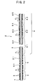
- the body 2 has an inner layer 7 and an outer layer 8.
- the coil 3 is interposed between the inner layer 7 and the outer layer 8.
- the outer layer 8 is provided on the outer side of the coil 3 to cover the coil 3. As shown in Figs. 2 and 3 , a part of the outer layer 8 (inner peripheral part of the outer layer 8) in its thickness direction is in penetration between adjacent windings of the coil 3 in the first region 4, the second region 5, and the third region 6. Owing to the penetration of a part of the coil 3 between the adjacent windings of the coil 3 and the variation of the winding pitch of the coil 3, in the first region 4, the outer layer 8 has a plurality of regions having different physical properties (rigidity, hardness) in its longitudinal direction. Thus, the first region 4 is bendable (low in rigidity) and flexible. Accordingly, although the winding pitch of the coil 3 in the first region 4 is shorter than the winding pitch thereof in the second region 5, the catheter 1 is so constructed that the rigidity thereof is lower in the first region 4 than in the second region 5.
- the following flexible materials are used: polyolefins such as polypropylene, ethylene-vinyl acetate copolymer; polyamide, polyesters such as polyethylene terephthalate (PET), polybutylene terephthalate (PBT); fluorocarbon resins such as polytetrafluoroethylene, ethylene-tetrafluoroethylene copolymer; polyurethane, polyvinyl chloride, polystyrene resin, flexible resins such as polyamide elastomer, polyurethane elastomer, polystyrene elastomer, polyester elastomer, fluoro-elastomer; rubber materials such as silicone rubber, latex rubber; and combinations of two or more of these substances.
- polyolefins such as polypropylene, ethylene-vinyl acetate copolymer
- polyamide polyesters such as polyethylene terephthalate (PET), polybutylene terephthalate (PBT); fluorocarbon resin
- the outer layer 8 has a first part 81 disposed at the front end of the catheter 1, a second part 82 disposed nearer to the rear end of the catheter 1 than the first part 81, a third part 83 disposed nearer to the rear end of the catheter 1 than the second part 82, a fourth part 84 disposed nearer to the rear end of the catheter 1 than the third part 83, a fifth part 85 disposed nearer to the rear end of the catheter 1 than the fourth part 84.
- the outer layer 8 is divided into a rear section consisting of the third part 83, the fourth part 84, and the fifth part 85; and a front section consisting of the first part 81 and the second part 82 and disposed nearer to the front end of the catheter 1 than the rear section.
- the front section (section consisting of the first part 81 and the second part 82) of the outer layer 8 having the lower rigidity extends throughout the first region 4. Thereby it is possible to compose the first region 4 bendably and flexibly (low in rigidity) and allow the catheter 1 to have improved follow-up performance.
- the catheter 1 Owing to the construction that the front section of the outer layer 8 has a lower rigidity than the rear section thereof and the change of the winding pitch of the coil 3, it is possible to decrease the rigidity of the catheter 1 continuously toward the front end thereof. In other words, even though the outer layer 8 is so constructed that it has a low rigidity in the first region 4, the catheter 1 has high kink resistance and pressure resistance. This is because the winding pitch of the coil 3 in the first region 4 is relatively low. Accordingly, the catheter 1 thus constructed displays high pressing performance and improved torque transmission performance at the rear side of the catheter 1 and displays superior flexibility and follow-up performance and in addition high kink resistance and pressure resistance at the front side thereof.
- each of the first part 81, the second part 82, the third part 83, the fourth part 84, and the fifth part 85 are not coincident with the front end and rear end of each of the first region 5, the second region 5, and the third region 6 in the longitudinal direction of the catheter 1.
- This construction allows the rigidity of the catheter 1 to decrease continuously toward the front end of the catheter 1. Accordingly, the bending rigidities of the respective regions of the body 2 balance favorably with each other.
- the construction allows the rear side of the body 2 to have a sufficient rigidity and thus allows it to display high pressing performance and torque transmission performance and also allows the front side of the body 2, particularly the first region 4 to display high follow-up performance, kink resistance, and safety.
- the hardness of the front section of the outer layer 8, namely, the hardness of each of the first and second parts 81 and 82 of the outer layer 8 is not limited to a specific value. However, the Shore D hardness thereof is favorably in the range of 10 to 60 and more favorably in the range of 20 - 50.
- the hardness of the rear section of the outer layer 8, namely, the hardness of each of the fifth, fourth, and third parts 85, 84, and 83 of the outer layer 8 is not limited to a specific value.
- the Shore D hardness thereof is favorably in the range of 60 to 80 and more favorably in the range of 62 - 75.
- the thickness of the outer layer 8 is not limited to a specific dimension.
- the thickness of the outer layer 8 is favorably in the range of 0.05 to 0.15mm and more favorably in the range of 0.06 to 0.12mm. If the thickness of the outer layer 8 is smaller than the lower limit value, there may be a case in which the pressing performance and the torque transmission performance are not displayed sufficiently. On the other hand, the outer layer 8 having a thickness larger than the upper limit value has a disadvantage in making the diameter of the body 2 small.
- the outer layer 8 is so constructed that its thickness is almost uniform from the rear end of the body 2 to its front end, but may decrease gradually toward the front end of the body 2.
- the rigidity (bending rigidity) of the catheter 1 decrease continuously. Therefore, the body 2 has improved follow-up performance and kink resistance.
- each of the first part 81, the second part 82, the third part 83, the fourth part 84, and the fifth part 85 is varied according to the kind of the catheter and not limited to a specific length.
- the following ranges are favorable for a micro-catheter for administering or injecting various medicines, a thrombus substance or a contrast medium to a desired portion of the internal organs such as brain or belly (for example, liver).
- the length of the first part 81 of the outer layer 8 is favorably in the range of 5 to 100mm.
- the length of the second part 82 of the outer layer 8 is favorably in the range of 30 to 200mm.
- the length of the third part 83 of the outer layer 8 is favorably in the range of 30 to 100mm.
- the length of the fourth part 84 of the outer layer 8 is favorably in the range of 30 to 100mm.
- the length of the fifth part 85 of the outer layer 8 is favorably in the range of 300 to 1500mm.
- the outer layer 8 is not limited to that of the embodiment.
- the outer layer 8 may be formed of the same material and may have the same rigidity (hardness) from the front end thereof 2 to its rear end.
- the outer layer has the front section and the rear section, that the front section is composed of a polyester elastomer, and that the rear section is composed of a polyurethane elastomer having a higher rigidity than the polyester elastomer.
- a hydrophilic polymeric substance can be preferably imparted to the outer surface of the catheter.
- the front section of the outer layer is formed from the front end of the body 2 to a position spaced at a certain interval from the front end of the body 2.
- the rear section of the outer layer is formed continuously with the front section and terminates at a rear end 21 of the body 2.
- the front section of the outer layer has a plurality of parts and that the hardness (rigidity) of a material composing each part of the front section of the outer layer decreases continuously or stepwise from the rear end of the front section toward its front end. It is also preferable that the hardness (rigidity) of the entirety of the outer layer 8 decreases continuously or stepwise from the rear end thereof toward the front end thereof.
- the catheter 1 in which the outer layer is composed as described above allows the bending rigidities of the respective regions of the body 2 to balance favorably with each other.
- the front section of the outer layer 8 is composed of the polyester elastomer and that rear section of the outer layer 8 is composed of the polyurethane elastomer.
- the hardness of the polyester elastomer is not limited to a specific value. However, the Shore D hardness thereof is favorably in the range of 25 to 60 and more favorably in the range of 28 - 55.
- the polyurethane elastomer for the rear section of the outer layer has a higher hardness than the polyester elastomer for the first region.
- the hardness of the polyurethane elastomer is not limited to a specific value.
- the Shore D hardness thereof is favorably in the range of 60 to 80 and more favorably in the range of 62 to 75.
- the catheter 1 has pressing performance, torque transmission performance, follow-up performance, and kink resistance balancing well with each other.
- polyester elastomer composing the front section of the outer layer it is possible to use a copolymer (random copolymer, block copolymer and the like) containing a hard segment and a soft segment.
- polybutylene terephthalate polyethylene terephthalate, dihidroxyparaquarterphenyl
- the polybutylene terephthalate is more favorable than the other substances.
- polytetramethylene terephthalate As the soft segment, it is possible to use polytetramethylene terephthalate, polytetramethylene ether glycol, poly (1,2-propylene oxide) glycol, poly (ethylene oxide) glycol, and polycaprolactam.
- the polytetramethylene terephthalate and the polytetramethylene ether glycol are more favorable than the other substances.
- polyurethane elastomer composing the rear section of the outer layer
- a copolymer random copolymer, block copolymer and the like
- polymers containing diisocyanate and short-chain glycol can be used.
- the diisocyanate the following substances can be used: 4,4'-diphenylmethanediisocyanate, 2,4'-toluenediisocyanate, 2,6-toluenediisocyanate, 1,6-hexamethylenediisocyanate, 3,3'-dimethyldiphenyl-4,4'-diisocyanate, 1,5'-naphthalanediisocyanate.
- the 4,4'-diphenylmethanediisocyanate is more favorable than the other substances.
- the short-chain glycol it is possible to use 1,4-butanediol, ethylene glycol; 1,3-propylene glycol; 1,3-butylene glycol; 1,4-butylene glycol; 1,6-hexyl glycol; 1,4-dimethylol benzene; and bisphenol A.
- 1,4-butanediol is more favorable than the other short-chain glycols.
- the soft segment it is possible to use polymers containing diisocyanate and long-chain glycol or use only the long-chain glycol.
- the diisocyanate it is possible to use the same substances as those which can be used for the hard segment. Of those substances, the 4,4'-diphenylmethanediisocyanate is more favorable than the other substances.
- the long-chain glycols the following substances can be used: polytetramethylene ether glycol, poly (oxypropylene) glycol, poly (ethylene adipate) glycol, poly (butylene-1,4-adipate) glycol, poly (ethylene-1,4-adipate) glycol, poly (hexanediol-1,6-carbonate) glycol, polycaprolactam glycol, poly (diethylene glycol adipate) glycol, and (hexanediol-1,6-carbonate) glycol.
- the polytetramethylene ether glycol is more favorable than the other glycols.
- the outer layer 8 of the polyester elastomer and the polyurethane elastomer By composing the outer layer 8 of the polyester elastomer and the polyurethane elastomer, it is easy to impart a hydrophilic polymeric substance which will be described later to the outer surface of the outer layer 8 and hold the hydrophilic polymeric substance thereon.
- the thickness of the outer layer 8 is not limited to a specific value.
- the thickness of the outer layer 8 is favorably in the range of 0.05 to 0.15mm and more favorably in the range of 0.06 to 0.12mm. If the thickness of the outer layer 8 is smaller than the lower limit value, there may be a case in which the pressing performance and the torque transmission performance are not displayed sufficiently. On the other hand, the outer layer 8 having a thickness larger than the upper limit value is at a disadvantage in making the diameter of the body 2 small.
- the thickness of the outer layer 8 is almost uniform from the rear end of the body 2 to its front end, but may decrease gradually toward the front end of the body 2.
- the rigidity (bending rigidity) of the body 2 decrease continuously. Therefore, the body has improved follow-up performance and kink resistance.
- the inner layer 7 covers the inner side of the coil 3.
- the inner layer 7 serves as the core for disposing the coil 3 in the body 2 and forms a lumen 21 therein.
- the material for the inner layer 7 it is possible to use a material similar to that for the outer layer 8. It is preferable to compose the inner layer 7 of a material having a low friction coefficient to allow the inner surface of the inner layer 7 to have a low degree of friction. Thereby it is possible to reduce the sliding-contact resistance of the inner layer 7 to the guide wire 9 (see Fig. 1 ) inserted into the lumen 21. Thus, it is possible to easily and smoothly perform an operation of inserting the catheter 1 into a blood vessel along the guide wire precedent to the front end of the catheter 1 and an operation of pulling out the guide wire from the catheter 1.
- Any material having a low friction coefficient can be used for the inner layer 7, so long as it can reduce the friction of the inner surface of the inner layer 7.
- fluorocarbon resin nylon 66, polyether ether ketone, and high-density polyethylene.
- the fluorocarbon resin is more favorable than the other substances.
- the fluorocarbon resin the following substances can be used: polytetrafluoroethylene, polyvinylidene fluoride, ethylene tetrafluoroethylene, and perfluoroalcoxy resin.
- the polytetrafluoroethylene is more favorable than the other substances.
- the thickness of the inner layer 7 is not limited to a specific value, but is favorably less than 50 ⁇ m and more favorably less than 40 ⁇ m.
- the inner layer 7 having a thickness larger than the upper limit value is at a disadvantage in making the diameter of the body 2 small.
- a part of the inner layer 7 in its thickness direction is in penetration between adjacent windings of the coil 3 in the first region 4, the second region 5, and the third region 6.
- the inner layer 7 Owing to the penetration of a part of the coil 3 between the adjacent windings of the coil 3 and the variation of the winding pitch of the coil 3, in the first region 4, the inner layer 7 has a plurality of regions having different physical properties (rigidity, hardness) in its longitudinal direction.
- the first region 4 is bendable (low in rigidity) and flexible. Accordingly, although the winding pitch of the coil 3 in the first region 4 is shorter than the winding pitch thereof in the second region 5, the catheter 1 is so constructed that the rigidity thereof is lower in the first region 4 than in the second region 5.
- the rigidity of the inner layer 7 having the higher rigidity acts mainly in the first region 4 as the entire rigidity of the catheter 1.
- the inner layer 7 is in penetration between the windings of the coil 3.
- the inner layer 7 is bendable and flexible (low in rigidity).
- the rigidity of the inner layer 7 in the first region 4 can be preferably reduced.
- the catheter 1 has a reduced rigidity in the first region 4 and is thus bendable.
- the coil 3 is wound on the periphery of the inner layer 7 by cutting the coil 3 into the periphery of the inner layer 7. Accordingly, the periphery of the inner layer 7 is compressed by the wound coil 3. It is possible to preferably penetrate the inner layer 7 between the adjacent windings of the coil 3 by winding the coil 3 in this manner.
- the catheter main body 2 that mentioned above can manufacture it by the method that expresses below.
- the inner layer 7 is mounted on the periphery of a mandrel (core material).
- the inner layer 7 can be formed by hollow extrusion molding, wire-coating molding or applying (or immersing) a solution containing a material for the inner layer 7 to the periphery of the core material and drying the solution.
- a wire namely, the coil 3 is wound spirally on the periphery of the inner layer 7 by varying the winding pitch of the coil 3 in the longitudinal direction of the mandrel to mount the coil 3 on the periphery of the inner layer 7.
- the wire is wound onto the periphery of the inner layer 7, with a predetermined winding tensile force applied to the wire.
- the inner layer 7 is compressed by the wound coil 3 and penetrates between the adjacent windings of the coil 3.
- the first part 81, the second part 82, the third part 83, the fourth part 84, and the fifth part 85 of the outer layer 8 are prepared as hollow tubular bodies by hollow extrusion molding more favorable than the wire-coating molding or wire-coating molding.
- the hardness, thickness, and length of each of the first part 81, the second part 82, the third part 83, the fourth part 84, and the fifth part 85 of the outer layer 8 are set to a predetermined value, respectively.
- the first part 81, the second part 82, the third part 83, the fourth part 84, and the fifth part 85 of the outer layer 8 are applied to the core material on which the inner layer 7 and the coil 3 have been mounted in a predetermined order.
- a heat-shrinkable tube is applied to the first part 81, the second part 82, the third part 83, the fourth part 84, and the fifth part 85 of the outer layer 8. Then, the heat-shrinkable tube is heated to thermally shrink it.
- the heat-shrinkable tube preferable consists of fluorocarbon resin.
- each of the first part 81, the second part 82, the third part 83, the fourth part 84, and the fifth part 85 of the outer layer 8 melts at the boundary between the first part 81 and the second part 82, between the second part 82 and the third part 83, between the third part 83 and the fourth part 84, and between the fourth part 84 and the fifth part 85. Consequently, the first part 81, the second part 82, the third part 83, the fourth part 84, and the fifth part 85 of the outer layer 8 become integral with each other.
- the melted first, second, third, fourth, and fifth parts 81, 82, 83, 84, and 85 of the outer layer 8 flow (penetrate) into the gap between the adjacent windings of the coil 3 and adhere to the periphery of the inner layer 7. In this manner, the inner layer 7 and the outer layer 8 become integral with each other.
- the heat-shrinkable tube is removed from the first, second, third, fourth, and fifth parts 81, 82, 83, 84, and 85 of the outer layer 8. Then, the end (unnecessary portion of the body 2) of the semi-finished product is cut off. Then, the mandrel is pulled out from the semi-finished product before or after the cut-off operation.
- extrusion molding method or dipping method may be used to apply a material for the outer layer 8 to the outer side of the coil 3 and the inner layer 7.
- a hydrophilic polymeric substance which will be described later is imparted to a predetermined portion of the outer surface of the catheter body 2 manufactured in this manner.
- the front end of the body 2 is tapered and the hub 11 is mounted on its rear end to complete the manufacture of the catheter 1.
- the outside diameter of the front end of catheter 1 is 1.5 mm or less, and are 1.0 mm or less desirably.
- the outer diameter of the body 2 is not limited to a specific dimension.
- a thrombus substance or a contrast medium to a desired portion of the internal organs (for example, liver) such as brain or belly it is preferable to set the outer diameter of the body 2 to the range of 0.5 to 1.0mm.
- the outer diameter of the body 2 is not limited to the range of 0.5 to 1.0mm in the case where the catheter of the present invention is not used as the micro-catheter.
- the hydrophilic polymeric substance it is preferable to apply the hydrophilic polymeric substance to the outer surface of the front side of the outer layer 8.
- the outer surface of the body 2 displays lubricity when it contacts a aqueous liquid such as blood or physiologic saline.
- the body has a decreased frictional and improved sliding performance. Consequently, the catheter 1 can be inserted into a blood vessel with high operability, namely, with high pressing performance, follow-up performance, kink resistance, and safety.
- the hydrophilic polymeric substance not to the entirety of the body 2 in the longitudinal direction of the body 2 but to the region thereof except a predetermined range (for example, 150 - 500mm) forward from the rear end of the body 2.
- hydrophilic polymeric substance the following natural or synthetic polymeric substances or derivatives of the polymeric substances can be used: a cellulose type polymeric substance (for example, hidroxypropyl cellulose), a polyethylene oxide polymeric substance (polyethylene glycol), a maleic anhydride type polymeric substances (for example, maleic anhydride copolymer such as methylvinyl ether maleic anhydride copolymer, copolymer of methyl vinyl ether and maleic anhydride ethyl ester, half-ester methyl vinyl ether-maleic anhydride copolymer neutralized, an acrylamide type polymeric substance (for example, polyacrylamide, dimethyl acrylamid-glycidyl methacrylate copolymer), and water-soluble nylon (for example, AQ-nylon P-70 manufactured by Toray Corp.). These polymeric substances are favorable because the friction coefficients thereof are stable.
- the maleic anhydride polymeric substance can be used more favorably than the other substances.
- the derivatives of the polymeric substances are not limited to water-soluble ones but water-insoluble ones can be also used, provided that they contain the polymeric substances as their fundamental component and that they are able to contain water and the molecular chains thereof have degree of freedom.
- any reactive functional groups present in the outer layer 8 or on the surface thereof or introduced thereinto can be used, provided that they react with the hydrophilic polymeric substance and combine with each other or cross-linked to each other and are then fixed to the outer surface of the body 2.
- the reactive functional groups the following substances can be used: diazonium group, azide group, isocyanate group, acid chloride group, acid anhydride group, imino carbonate group, amino group, carboxylic group, epoxy group, hydroxyl group, and aldehyde group. Of these groups, the isocyanate group, the amino group, the aldehyde group, and the epoxy group are more favorable than the other groups.
- the present invention is not limited to the embodiment described above with reference to Figs. 1 through 3 .
- the tubular member (body 2) of the present invention is not limited to the construction, of the above-described embodiment, having the inner layer and the outer layer.
- the body 2 (tubular member) may have a single layer 301 in which the coil 3 is embedded.
- Fig. 4 is an enlarged sectional view showing the front side of the catheter according to another embodiment of the present invention.
- the catheter 30 has an effect similar to that of the catheter 1 shown in Figs. 1 through 3 .
- the catheter 30 is different from that catheter 1 in only the above-described construction.
- the catheter 30 has the same construction as that of the catheter 1 described with reference to Figs. 1 through 3 .
- the construction of the tubular member (body 2) of the present invention is not limited to the construction having both the inner layer and the outer layer penetrating between adjacent windings of the coil 3.
- a catheter 40 in a catheter 40, only the inner layer 7 penetrates between the adjacent windings of the coil 3, whereas the outer layer 8 provided on the outer side of the coil 3 does not penetrate between the adjacent windings of the coil 3.
- Fig. 5 is an enlarged sectional view showing the front side of the catheter according to another embodiment of the present invention.
- the outer layer 8 is liquid-tightly fixed to the periphery of the inner layer 7 with an adhesive agent or fused thereto in the region 41 disposed forward from the front end of the coil 3.
- the catheter 40 has also an effect similar to that of the catheter 1 shown in Figs. 1 through 3 .
- the catheter 40 is different from that catheter 1 in the above-described construction.
- the catheter 40 has the same construction as that of the catheter 1 described with reference to Figs. 1 through 3 .
- the catheter of the present invention can be so constructed that only the outer layer 8 penetrates between the adjacent windings of the coil 3, whereas the inner layer 7 provided on the inner side of the coil 3 does not penetrate between the adjacent windings of the coil 3.
- the catheter may have one layer or two or more layers in addition to the inner layer 7 and the outer layer 8.
- the catheter of the present invention is not limited to a specific application. It can be used as a guiding catheter; a contrast medium-introducing catheter; balloon catheters such as for PTCA, PTA, IABP; an ultrasonic wave catheter, an atherectomy catheter, a catheter for an endoscope, an indwelling catheter, a medicine-administering catheter, a micro-catheter (for embolization) for administering or injecting various medicines, a thrombus substance or a contrast medium to a desired portion of the internal organs (for example, liver) such as brain or belly.
- the catheter of the present invention is particularly advantageous because it can have a small diameter. The catheter having a small diameter can display the above-described effect efficiently.
- the catheter of the present invention as the micro-catheter.
- Polytetrafluoroethylene was applied to a mandrel (core material) made of silver-plated soft copper wire having a diameter of 0.65mm by molding to form the inner layer 7 having a thickness of 35 ⁇ m on the peripheral surface of the mandrel.
- the peripheral surface of the inner layer 7 was chemically treated with a solution consisting of a glicolic solvent and a solute of naphthalene complex of sodium salt.
- the core material coated with the inner layer 7 was cut to a length of 1500mm.
- a metal wire material of tungsten having a diameter of 50 ⁇ m was wound on the peripheral surface of the inner layer 7 by changing a winding pitch with a winding tensile force kept at 0.17kg to form the coil 3.
- the end of the metal wire material forming the coil 3 was cut off.
- the outer layer 8 was formed on the peripheral surface of the inner layer 7 formed on the core material and on the coil 3 formed on the peripheral surface of the inner layer 7 as follows:
- the first part 81, the second part 82, the third part 83, the fourth part 84, and the fifth part 85 of the outer layer 8 were formed as hollow tubular members by extrusion molding.
- the first part 81, the second part 82, the third part 83, the fourth part 84, and the fifth part 85 of the outer layer 8 were placed in a predetermined order on the core material on which the first layer 4 and the second layer 5 were formed.
- a heat-shrinkable tube made of fluorocarbon resin was applied to the peripheral surface of the first part 81, the second part 82, the third part 83, the fourth part 84, and the fifth part 85 of the outer layer 8. Both ends of the heat-shrinkable tube was fixed with a stopper.
- the semi-finished product was passed into a heat tunnel for 10 minutes at 340°C to fuse and connect the first part 81 and the second part 82 to each other, the second part 82 and the third part 83 to each other, the third part 83 and the fourth part 84 to each other, and the fourth part 84 and the fifth part 85 to each other.
- the heat-shrinkable tube was separated from the outer layer 8. Then, the part of the semi-finished product on which the outer layer 8 was not present was cut in a length of 200 mm from the end thereof. The mandrel was pulled out from the semi-finished product. In this manner, the body 2 having the first region 4 consisting of the region, 41, 42, 43, 44, and 45; the second region 5, and the third region 6 consisting of the parts 61, 62, and 63 was prepared.
- each of the first region 4 region, 41, 42, 43, 44, and 45
- the second region 5 region 5, and the third region 6 (parts 61, 62, and 63)
- the first part 81, the second part 82, the third part 83, the fourth part 84, and the fifth part 85 of the outer layer 8 is as follows:
- a tetrahidrofuran (THF) solution of diphenylmethyl-diisocyanate adjusted to 5.3% was applied to the outer surface of the body 2. Then, the solution was dried for 30 minutes at the room temperature.
- THF tetrahidrofuran
- treatment conducted twice was to apply the THF solution of a half-ester methyl vinyl ether-maleic anhydride copolymer neutralized adjusted to 1.65% to the peripheral surface of the body 2 and dry the solution for 30 minutes at the room temperature. Then, neutralization cleaning and pure water cleaning were performed, and the THF solution was dried.
- the hub 11 was connected to the rear end of the body 2 to which the hydrophilic polymeric substance was applied to manufacture the catheter of the present invention.
- a tubular member (first test example) was prepared by a method similar to that used to prepare the body 2 of the first example, except that the region 41 (region in which the coil 3 is not present) formed in the first example was not formed and that the coil 3 was wound from the front end of the inner layer 7 to its rear end.
- the winding pitch of the coil 3 was changed in the same manner as that of the first example.
- the coil 3 was wound over the whole length of the tubular member similarly to the second through sixth test examples.
- the tubular member of the second test example was prepared in a manner similar to that used to prepare the body 2 of the first example, except that the coil 3 was wound over the whole length thereof at regular pitches of 95 ⁇ m.
- the tubular member of the third test example was prepared in a manner similar to that used to prepare the body 2 of the first example, except that the coil 3 was wound over the whole length thereof at regular pitches of 200 ⁇ m.
- the tubular member of the fourth test example was prepared in a manner similar to that used to prepare the body 2 of the first example, except that the coil 3 was wound over the whole length thereof at regular pitches of 290 ⁇ m.
- the tubular member of the fifth test example was prepared in a manner similar to that used to prepare the body 2 of the first example, except that the coil 3 was wound over the whole length thereof at regular pitches of 350 ⁇ m.
- the tubular member of the sixth test example was prepared in a manner similar to that used to prepare the body 2 of the first example, except that the coil 3 was wound over the whole length thereof at regular pitches of 400 ⁇ m.
- Table 1 indicates that when the winding pitch of the coil 3 was uniform over the whole length of each test example, the striking resistance was lowest when the winding pitch was in the neighborhood of 200 ⁇ m (third test example). Table 1 also indicates that as the winding pitch became shorter (second test example) than 200 ⁇ m or longer (fourth through sixth test examples) than 200 ⁇ m, the striking resistance became increasingly high. That is, it has been confirmed that when the winding pitch of the coil 3 was uniform over the whole length of each test example, the tubular member became most flexible (lowest in rigidity) in the neighborhood of 200 ⁇ m and that the tubular member became hard (high in rigidity) when the winding pitch was longer or shorter than 200 ⁇ m.
- the winding pitch of the coil 3 of the first test example at its rear end was almost equal (220 ⁇ m) to that of the third test example at its rear end and became gradually shorter and was equal (95 ⁇ m) to that of the second test example at its front side.
- the maximum striking resistance of the first test example was lower than that of any of the second through sixth test examples. It has been also confirmed the maximum striking resistance of the first test example at the position of 5mm rearward from its front end was much lower than that of each of the second through sixth test examples.
- the first test example was more flexible (lower in rigidity) than any of the second through sixth test examples because in the first test example, the winding pitch of the coil 3 was changed from about 200 ⁇ m to 95 ⁇ m in the very short length (about 5mm), whereas in the second through sixth test examples, the winding pitch was uniformly about 200 ⁇ m.
- the catheter 1 of the first example had a lower rigidity and was thus more flexible in the first region 4 in which the winding pitch of the coil 3 was changed in the same manner as that of the first test example than in the second region 5 having the winding pitch similar to that of the third test example. That is, it has been confirmed the catheter could be formed flexibly by gradually reducing the winding pitch of the coil toward the front end of the catheter, although the coil was wound, with adjacent windings very close to each other in the predetermined length (for example, 5mm) rearward from the front end of the catheter.
- the predetermined length for example, 5mm
- Table 1 also indicates that the catheter (body) had a higher rigidity in the third region 6 than in the second region 5 because the winding pitch (about 200 ⁇ m) which makes the rigidity (flexural rigidity) of the catheter minimum was selected in the second region 5 of the catheter 1 of the first example and the winding pitch of the coil 3 in the third region 6 was longer than that in the second region 5.
- the rigidity necessary for the catheter can be secured and high pressing performance is superior at its rear side, whereas flexibility (bendability) and follow-up performance are superior at its front side.
- the catheter body was prepared in accordance with the procedure of the first example, except that the following substances were used as the first part 81 and the second part 82 of the outer layer of the body.
- First part 81 of outer layer polyurethane elastomer (PELLETHANE TM manufactured by Dow Chemical Japan Corp., Shore D hardness: 30) Thickness: 0.08mm, Length: 40mm
- Second part 82 of outer layer polyurethane elastomer (PELLETHANE TM manufactured by Dow Chemical Japan Corp., Shore D hardness: 40) Thickness: 0.08mm, Length: 130mm
- the catheter body 2 was prepared in accordance with the procedure of the first example, except that the following substances were used as the third part 83, the fourth part 84, and the fifth part 85 of the outer layer of the body.
- *Fourth part 84 of outer layer polyester elastomer (PELPRENE TM manufactured by Toyobo.co.,Ltd., Shore D hardness: 57) Thickness: 0.09mm, Length: 30mm *Fifth part 85 of outer layer: polyester elastomer (PELPRENE TM manufactured by Toyobo.co.,Ltd., Shore D hardness: 68) Thickness: 0.10mm, Length: 1000mm
- each catheter was examined on the state of its outer surface and the lubricity-holding effect of the outer surface.
- the tetrahidrofuran (THF) solution of diphenylmethyl-diisocyanate adjusted to 5.3% was applied to the outer surface of the catheter body 2 of each of the first example, the first comparison example, and the second comparison example. Then, the solution was dried for 30 minutes at the room temperature.
- THF tetrahidrofuran
- the treatment conducted twice was to apply the THF solution of the half-ester methyl vinyl ether-maleic anhydride copolymer neutralized (hydrophilic polymeric substance) adjusted to 1.65% to the peripheral surface of the body 2 of the catheter of each of the first example, the first comparison example, the second comparison example and dry the solution for 30 minutes at the room temperature. Then, neutralization cleaning and pure water cleaning were performed and water content was dried.
- the catheter body 2 of the first example and that of the second comparison example were repeatedly put into a commercially available angiography catheter manufactured by Terumo Kabushiki Kaisha and slid repeatedly longitudinally on the inner peripheral surface of the angiography catheter in which physiologic saline was filled, with the outer surface of both catheter bodies 2 wet with the physiologic saline.
- the winding pitch of the coil in the second region located at the rear side of the catheter is set relatively long, whereas the winding pitch of the coil in the first region located at the front end of the catheter is relatively short, with the winding pitch becoming gradually shorter toward the front end of the catheter. Therefore, the catheter has high operability such as pressing performance, follow-up performance, and kink resistance and in addition pressure resistance.
- the rigidity of the region of the catheter body at its rear side higher than that of the region thereof at its front side, it is possible to improve the operability of the catheter such as pressing performance, torque transmission performance, follow-up performance, and kink resistance.
- the catheter of the present invention can display high kink resistance and pressure resistance without sacrificing the flexibility (low rigidity, bendability) at its front end and has an advantage in making the diameter of its body small.
- the catheter is suitably applied to the micro-catheter.
Landscapes
- Health & Medical Sciences (AREA)
- Life Sciences & Earth Sciences (AREA)
- Biophysics (AREA)
- Pulmonology (AREA)
- Engineering & Computer Science (AREA)
- Anesthesiology (AREA)
- Biomedical Technology (AREA)
- Heart & Thoracic Surgery (AREA)
- Hematology (AREA)
- Animal Behavior & Ethology (AREA)
- General Health & Medical Sciences (AREA)
- Public Health (AREA)
- Veterinary Medicine (AREA)
- Media Introduction/Drainage Providing Device (AREA)
- Materials For Medical Uses (AREA)
Claims (22)
- Ein Katheter mit einem äußeren Durchmesser, der an seinem vorderen Ende nicht größer als 1,5 mm ist, das einen flexiblen rohrförmigen Rumpf (2) mit einer in einer Wand des Rumpfes (2) eingebetteten Versteifungsspirale (3) aufweist, dadurch gekennzeichnet, dass der rohrförmige Rumpf einen ersten Bereich (4) innerhalb von 1 bis 30 mm von dem vorderen Ende des Katheters und einen zweiten Bereich (5), der näher zu einem hinteren Ende des Katheters als der erste Bereich (4) ist, aufweist, wobei die Spirale sich von einer Position innerhalb des ersten Bereichs (4) bis zu dem zweiten Bereich erstreckt, wobei ein Teil der Spirale in dem zweiten Bereich mit einer langen Wicklungsganghöhe, was die Länge des Zwischenraums zwischen benachbarten Wicklungen der Spirale in der Längsrichtung des Katheters ist, gewickelt ist, wobei ein in dem ersten Bereich angeordneter Teil der Spirale eine Wicklungsganghöhe aufweist, die kürzer als die des in dem zweiten Bereich angeordneten Teils der Spirale ist und die in Richtung zum vorderen Ende des Katheters gleichförmig oder schrittweise kürzer wird, wobei der in dem ersten Bereich (4) angeordneten Teil der Spirale integral mit dem in dem zweiten Bereich (5) angeordneten Teil der Spirale ist.
- Ein Katheter nach Anspruch 1, wobei der Rumpf (2) einen dritten Bereich (6), der näher zu dem hinteren Ende des Katheters als der zweite Bereich ist, aufweist;
wobei die Spirale sich von dem ersten Bereich (4) bis zu dem dritten Bereich (6) erstreckt;
wobei eine Wicklungsganghöhe eines in dem dritten Bereich (6) angeordneten Teils der Spirale länger als der des in dem zweiten Bereich (5) angeordneten Teils der Spirale ist, wobei eine Steifigkeit des Katheters in dem dritten Bereich höher als in dem zweiten Bereich ist. - Ein Katheter nach Anspruch 1 oder 2, wobei eine Beziehung zwischen einer Wicklungsganghöhe (sei) der Spirale an einem hinteren Ende des ersten Bereichs (4) und einer Wicklungsganghöhe (E) der Spirale an einem vorderen Ende derselben lautet: E ≦ 3/4 x S1.
- Ein Katheter nach einem der Ansprüche 1 bis 3, wobei eine Wicklungsganghöhe der Spirale in dem ersten Bereich (4) im Bereich von 30 µm bis 300 µm ist.
- Ein Katheter nach einem der Ansprüche 1 bis 4, wobei die Spirale (3) aus einem röntgenstrahlenundurchlässigen Material hergestellt ist.
- Ein Katheter nach einem der Ansprüche 1 bis 5, wobei eine Wicklungsganghöhe eines Teils der Spirale (3), die innerhalb von 5 mm von einem vorderen Ende des Katheters beabstandet angeordnet ist, im Bereich von 30 µm bis 300 µm ist.
- Ein Katheter nach einem der Ansprüche 1 bis 6, wobei eine Beziehung zwischen einer Wicklungsganghöhe (S2) der Spirale (3) an einer Position, die 5 mm beabstandet von einem vorderen Ende des Katheters ist, und einer Wicklungsganghöhe (E) der Spirale an deren vorderem Ende lautet: E ≦ 3/4 x S2.
- Ein Katheter nach einem der Ansprüche 1 bis 7, wobei ein äußerer Durchmesser eines Teils des Katheters, der innerhalb von 5 mm beabstandet von einem vorderen Ende des Katheters angeordnet ist, weniger als 1 mm ist.
- Ein Katheter nach einem der Ansprüche 1 bis 8, wobei die Spirale keinen Teilbereich aufweist, in dem ihre Wicklungsganghöhe in Richtung zum vorderen Ende des Katheters länger wird.
- Ein Katheter nach einem der Ansprüche 1 bis 9, wobei ein Teilbereich, in dem die Spirale nicht vorhanden ist, an einem vorderen Ende des Katheters ausgebildet ist.
- Ein Katheter nach einem der Ansprüche 1 bis 10, wobei der Rumpf (2) des Katheters einen hinteren Abschnitt und einen vor dem hinteren Abschnitt angeordneten, vorderen Abschnitt aufweist; und wobei der vordere Abschnitt eine niedrigere Steifigkeit als der hintere Abschnitt aufweist.
- Ein Katheter nach Anspruch 11, wobei der vordere Abschnitt mindestens eine Gesamtlänge des ersten Bereichs aufweist.
- Ein Katheter nach einem der Ansprüche 1 bis 12, wobei der Rumpf (2) des Katheters eine innere Schicht (7) und eine äußere Schicht (8) aufweist; und wobei die Spirale (3) zwischen der inneren Schicht und der äußeren Schicht eingebettet ist.
- Ein Katheter nach Anspruch 13, wobei die äußere Schicht einen hinteren Abschnitt und einen vor dem hinteren Abschnitt angeordneten, vorderen Abschnitt aufweist; und wobei der vordere Abschnitt eine niedrigere Steifigkeit als der hintere Abschnitt aufweist.
- Ein Katheter nach Anspruch 14, wobei der vordere Abschnitt der äußeren Schicht eine Gesamtheit des ersten Bereichs umfasst.
- Ein Katheter nach Anspruch 14 oder 15, wobei der vordere Abschnitt der äußeren Schicht aus einem Polyesterelastomer besteht; und wobei der hintere Abschnitt der äußeren Schicht aus einem Polyurethanelastomer mit einer höheren Steifigkeit als das Polyesterelastomer zusammengesetzt ist.
- Ein Katheter nach einem der Ansprüche 13 bis 16, wobei die innere Schicht aus einem Fluorkohlenstoff-Harz hergestellt ist.
- Ein Katheter nach einem der Ansprüche 13 bis 17, wobei ein Teil der inneren Schicht in ihrer Dickenrichtung in Durchdringung zwischen benachbarten Wicklungen der Spirale ist.
- Ein Katheter nach einem der Ansprüche 13 bis 18, wobei die innere Schicht eine höhere Steifigkeit als die äußere Schicht in dem ersten Bereich aufweist.
- Ein Katheter nach einem der Ansprüche 1 bis 18, wobei auf eine Oberfläche von mindestens einer vorderen Seite der äußeren Schicht eine hydrophile Polymersubstanz aufgebracht ist.
- Ein Katheter nach einem der Ansprüche 1 bis 20, das ein Lumen für einen Führungsdraht aufnimmt und das in einem gewünschten Teilbereich eines menschlichen Körpers entlang des in das Lumen eingeführten Führungsdrahts eingeführt werden kann.
- Ein Katheter nach einem der Ansprüche 1 bis 21, wobei das Katheter ein Mikro-Katheter ist, das dazu ausgebildet ist, in ein peripheres Blutgefäss mit einem Durchmesser von weniger als 3 mm eingeführt zu werden.
Applications Claiming Priority (2)
| Application Number | Priority Date | Filing Date | Title |
|---|---|---|---|
| JP2000038023A JP3915862B2 (ja) | 2000-02-09 | 2000-02-09 | カテーテル |
| JP2000038023 | 2000-02-09 |
Publications (2)
| Publication Number | Publication Date |
|---|---|
| EP1123714A1 EP1123714A1 (de) | 2001-08-16 |
| EP1123714B1 true EP1123714B1 (de) | 2009-08-26 |
Family
ID=18561829
Family Applications (1)
| Application Number | Title | Priority Date | Filing Date |
|---|---|---|---|
| EP01102729A Revoked EP1123714B1 (de) | 2000-02-09 | 2001-02-07 | Katheter |
Country Status (5)
| Country | Link |
|---|---|
| US (1) | US6451005B1 (de) |
| EP (1) | EP1123714B1 (de) |
| JP (1) | JP3915862B2 (de) |
| AT (1) | ATE440631T1 (de) |
| DE (1) | DE60139650D1 (de) |
Families Citing this family (135)
| Publication number | Priority date | Publication date | Assignee | Title |
|---|---|---|---|---|
| US6216045B1 (en) | 1999-04-26 | 2001-04-10 | Advanced Neuromodulation Systems, Inc. | Implantable lead and method of manufacture |
| US7316677B1 (en) * | 1999-04-30 | 2008-01-08 | Applied Medical Resources Corporation | Ureteral access sheath |
| WO2001007101A1 (en) * | 1999-07-23 | 2001-02-01 | Tfx Medical Extrusion Products | Catheter device having multi-lumen reinforced shaft and method of manufacture for same |
| US7555349B2 (en) * | 2000-09-26 | 2009-06-30 | Advanced Neuromodulation Systems, Inc. | Lead body and method of lead body construction |
| US7149585B2 (en) * | 2001-03-30 | 2006-12-12 | Micronet Medical, Inc. | Lead body and method of lead body construction |
| US6939593B2 (en) * | 2001-08-27 | 2005-09-06 | Scimed Life Systems, Inc. | Medical devices utilizing melt-processible poly(tetrafluoroethylene) |
| US7927368B2 (en) * | 2002-03-25 | 2011-04-19 | Kieran Murphy Llc | Device viewable under an imaging beam |
| US9375203B2 (en) | 2002-03-25 | 2016-06-28 | Kieran Murphy Llc | Biopsy needle |
| US20030181810A1 (en) | 2002-03-25 | 2003-09-25 | Murphy Kieran P. | Kit for image guided surgical procedures |
| EP1551489B1 (de) * | 2002-10-10 | 2009-12-09 | Micro Therapeutics, Inc. | Mit drahtgeflecht verstärkter mikrokatheter |
| US20050165366A1 (en) | 2004-01-28 | 2005-07-28 | Brustad John R. | Medical tubing having variable characteristics and method of making same |
| US7005026B2 (en) * | 2002-11-15 | 2006-02-28 | Applied Medical Resources Corporation | Kink-resistant access sheath and method of making same |
| US20050256452A1 (en) * | 2002-11-15 | 2005-11-17 | Demarchi Thomas | Steerable vascular sheath |
| US20050004515A1 (en) * | 2002-11-15 | 2005-01-06 | Hart Charles C. | Steerable kink resistant sheath |
| CA2522175C (en) | 2003-04-14 | 2009-07-28 | Cook Incorporated | Large diameter delivery catheter/sheath |
| ATE378085T1 (de) | 2003-04-28 | 2007-11-15 | Cook Inc | Flexible einführschleuse mit unterschiedlichem durometer |
| US7597830B2 (en) | 2003-07-09 | 2009-10-06 | Boston Scientific Scimed, Inc. | Method of forming catheter distal tip |
| JP4617070B2 (ja) * | 2003-07-29 | 2011-01-19 | テルモ株式会社 | 拡張体付カテーテル |
| US20050027340A1 (en) * | 2003-07-29 | 2005-02-03 | Micronet Medical, Inc. | System and method for providing a medical lead body having dual conductor layers |
| US20050027341A1 (en) * | 2003-07-29 | 2005-02-03 | Micronet Medical, Inc. | System and method for providing a medical lead body having conductors that are wound in opposite directions |
| US20050027339A1 (en) * | 2003-07-29 | 2005-02-03 | Micronet Medical, Inc. | System and method for providing a medical lead body |
| US7641647B2 (en) * | 2003-12-29 | 2010-01-05 | Boston Scientific Scimed, Inc. | Medical device with modified marker band |
| DK1715827T3 (da) * | 2004-01-23 | 2011-04-18 | Iscience Interventional Corp | Sammensat ophthalmisk mikrokanyle |
| JP2005270250A (ja) * | 2004-03-24 | 2005-10-06 | Kawasumi Lab Inc | 医療用チューブ |
| JP2005334242A (ja) * | 2004-05-26 | 2005-12-08 | Kaneka Corp | 医療用カテーテルチューブならびにその製造方法 |
| JPWO2006016481A1 (ja) * | 2004-08-10 | 2008-05-01 | 株式会社カネカ | 医療用カテーテルチューブならびにその製造方法 |
| US7771411B2 (en) | 2004-09-24 | 2010-08-10 | Syntheon, Llc | Methods for operating a selective stiffening catheter |
| US7621904B2 (en) | 2004-10-21 | 2009-11-24 | Boston Scientific Scimed, Inc. | Catheter with a pre-shaped distal tip |
| JP2008518687A (ja) * | 2004-11-01 | 2008-06-05 | アプライド メディカル リソーシーズ コーポレイション | 長さ方向シース補強体 |
| DE102004057481B4 (de) * | 2004-11-19 | 2008-08-07 | Karl Storz Gmbh & Co. Kg | Flexibler Schaft für ein Endoskop sowie derartiges Endoskop |
| JP4647299B2 (ja) * | 2004-12-09 | 2011-03-09 | 株式会社カネカ | 医療用カテーテルチューブならびにその製造方法 |
| EP1825879A1 (de) * | 2004-12-09 | 2007-08-29 | Kaneka Corporation | Medizinischer katheterschlauch und verfahren zu seiner herstellung |
| EP1839686B1 (de) * | 2005-01-21 | 2011-07-20 | Terumo Kabushiki Kaisha | Katheter und herstellungsverfahren dafür |
| JP4754843B2 (ja) * | 2005-02-21 | 2011-08-24 | 株式会社パイオラックスメディカルデバイス | カテーテル |
| JP2006288943A (ja) * | 2005-04-14 | 2006-10-26 | Kaneka Corp | 医療用カテーテルチューブならびにその製造方法 |
| JP2006288944A (ja) * | 2005-04-14 | 2006-10-26 | Kaneka Corp | 医療用カテーテルチューブならびにその製造方法 |
| JP4771456B2 (ja) * | 2005-05-13 | 2011-09-14 | テルモ株式会社 | カテーテル |
| JP2006314714A (ja) * | 2005-05-16 | 2006-11-24 | Olympus Medical Systems Corp | 結石破砕装置 |
| JP2007000392A (ja) * | 2005-06-24 | 2007-01-11 | Kaneka Corp | カテーテルチューブ |
| JP2007029510A (ja) * | 2005-07-28 | 2007-02-08 | Kaneka Corp | 医療用カテーテルチューブならびにその製造方法 |
| US9814372B2 (en) | 2007-06-27 | 2017-11-14 | Syntheon, Llc | Torque-transmitting, variably-flexible, locking insertion device and method for operating the insertion device |
| US10123683B2 (en) | 2006-03-02 | 2018-11-13 | Syntheon, Llc | Variably flexible insertion device and method for variably flexing an insertion device |
| US20070233040A1 (en) * | 2006-03-31 | 2007-10-04 | Boston Scientific Scimed, Inc. | Flexible endoscope with variable stiffness shaft |
| WO2007137184A2 (en) | 2006-05-18 | 2007-11-29 | Applied Medical Resources Corporation | Method of making medical tubing having variable characteristics using thermal winding |
| EP2062609B1 (de) * | 2006-09-13 | 2011-06-29 | Kawasumi Laboratories, Inc. | Mikrokatheter |
| JP5030514B2 (ja) | 2006-09-15 | 2012-09-19 | オリンパスメディカルシステムズ株式会社 | 内視鏡及び内視鏡システム |
| JP4929956B2 (ja) * | 2006-09-29 | 2012-05-09 | 株式会社カネカ | 医療デバイス通過用チューブ及びそれを備えたカテーテル |
| JP2008104579A (ja) * | 2006-10-24 | 2008-05-08 | Kaneka Corp | マイクロカテーテル |
| JP2008104657A (ja) * | 2006-10-25 | 2008-05-08 | Kaneka Corp | 医療用バルーンカテーテル |
| JP5080094B2 (ja) * | 2007-01-30 | 2012-11-21 | 平河ヒューテック株式会社 | カテーテル用チューブの連続体、及び、カテーテル用チューブの製造方法 |
| US20080188830A1 (en) * | 2007-02-06 | 2008-08-07 | Arrow International, Inc. | Selectively reinforced medical devices |
| JP4796534B2 (ja) * | 2007-04-18 | 2011-10-19 | 平河ヒューテック株式会社 | カテーテル用チューブの製造方法 |
| US8167809B2 (en) | 2007-12-20 | 2012-05-01 | Silicon Valley Medical Instruments, Inc. | Imaging probe housing with fluid flushing |
| US20090287189A1 (en) * | 2008-05-14 | 2009-11-19 | Becton, Dickinson And Company | Optimal radiopaque catheter |
| US20090312698A1 (en) * | 2008-06-16 | 2009-12-17 | Greatbatch Ltd. | Bi-directional steerable sheath |
| AU2010225987B2 (en) * | 2009-03-19 | 2015-09-03 | Japan Lifeline Co., Ltd. | Medical guide wire |
| US9936892B1 (en) * | 2009-05-04 | 2018-04-10 | Cortex Manufacturing Inc. | Systems and methods for providing a fiducial marker |
| EP2433668B1 (de) | 2009-05-20 | 2014-01-22 | Japan Lifeline Co., Ltd. | Medizinischer führungsdraht |
| JP5636656B2 (ja) * | 2009-09-17 | 2014-12-10 | 住友ベークライト株式会社 | カテーテル |
| JP2011110138A (ja) * | 2009-11-25 | 2011-06-09 | Sumitomo Bakelite Co Ltd | カテーテル |
| US8034045B1 (en) * | 2010-05-05 | 2011-10-11 | Cook Medical Technologies Llc | Flexible sheath |
| US10226167B2 (en) | 2010-05-13 | 2019-03-12 | Beaver-Visitec International, Inc. | Laser video endoscope |
| US20160095507A1 (en) | 2010-05-13 | 2016-04-07 | Beaver-Visitec International, Inc. | Laser video endoscope |
| US20120265010A1 (en) * | 2011-04-12 | 2012-10-18 | Endo Optiks, Inc. | Laser Video Endoscope |
| KR101588097B1 (ko) | 2010-10-04 | 2016-01-22 | 코비디엔 엘피 | 말단부 접근 흡인 유도 카테터 |
| JP5736735B2 (ja) * | 2010-11-09 | 2015-06-17 | 住友ベークライト株式会社 | カテーテル |
| US9192754B2 (en) * | 2011-01-27 | 2015-11-24 | Carefusion 303, Inc. | Low permeability silicone rubber tubing |
| KR101879012B1 (ko) | 2011-02-25 | 2018-07-16 | 마이크로벤션, 인코포레이티드 | 강화 풍선 카테터 |
| CA2830514A1 (en) | 2011-03-22 | 2012-09-27 | Applied Medical Resources Corporation | Method of making medical tubing having drainage holes |
| US9521990B2 (en) * | 2011-05-11 | 2016-12-20 | Acist Medical Systems, Inc. | Variable-stiffness imaging window and production method thereof |
| US10130789B2 (en) * | 2011-06-30 | 2018-11-20 | Covidien Lp | Distal access aspiration guide catheter |
| WO2013022796A2 (en) | 2011-08-05 | 2013-02-14 | Silk Road Medical, Inc. | Methods and systems for treatment of acute ischemic stroke |
| US10779855B2 (en) | 2011-08-05 | 2020-09-22 | Route 92 Medical, Inc. | Methods and systems for treatment of acute ischemic stroke |
| JP5918853B2 (ja) * | 2011-09-12 | 2016-05-18 | ストライカー・ユーロピアン・ホールディングス・I,リミテッド・ライアビリティ・カンパニー | フレキシブルな高分子の螺旋状の医療用チューブの製造方法、該製造方法によって作られたチューブ及び該チューブの用途 |
| EP2572749B1 (de) | 2011-09-23 | 2022-04-27 | Covidien LP | Ballonführungskatheter für distalen Zugang |
| JP2013090717A (ja) * | 2011-10-25 | 2013-05-16 | Goodtec Co Ltd | カテーテル |
| WO2013077275A1 (ja) * | 2011-11-25 | 2013-05-30 | テルモ株式会社 | 医療用チューブおよびカテーテル |
| US10548706B2 (en) * | 2012-01-13 | 2020-02-04 | Volcano Corporation | Retrieval snare device and method |
| JP5994335B2 (ja) * | 2012-03-30 | 2016-09-21 | 住友ベークライト株式会社 | カテーテル |
| CN105073173B (zh) * | 2013-01-18 | 2017-05-10 | 斯坦福国际研究院 | 锚定神经阻滞导管 |
| US10953193B2 (en) * | 2013-07-16 | 2021-03-23 | Covidien Lp | Microcatheter with modified PTFE liner |
| WO2015046148A1 (ja) | 2013-09-30 | 2015-04-02 | テルモ株式会社 | カテーテル |
| CN114533123A (zh) | 2013-12-19 | 2022-05-27 | 阿西斯特医疗系统有限公司 | 导管包壳系统和方法 |
| US9265512B2 (en) | 2013-12-23 | 2016-02-23 | Silk Road Medical, Inc. | Transcarotid neurovascular catheter |
| JP5682719B1 (ja) * | 2014-02-27 | 2015-03-11 | 住友ベークライト株式会社 | カテーテルおよびカテーテルの製造方法 |
| US10426497B2 (en) | 2015-07-24 | 2019-10-01 | Route 92 Medical, Inc. | Anchoring delivery system and methods |
| DE202016009165U1 (de) | 2015-02-04 | 2023-04-26 | Route 92 Medical, Inc. | System für schnelle Aspirationsthrombektomie |
| US11065019B1 (en) | 2015-02-04 | 2021-07-20 | Route 92 Medical, Inc. | Aspiration catheter systems and methods of use |
| JP5967255B2 (ja) * | 2015-04-15 | 2016-08-10 | 住友ベークライト株式会社 | カテーテル及びカテーテルの製造方法 |
| AU2016266748B2 (en) * | 2015-05-05 | 2019-01-17 | W. L. Gore & Associates, Inc. | Shaped delivery sheath and methods |
| JP6928203B2 (ja) | 2015-05-26 | 2021-09-01 | テルモ・クリニカルサプライ株式会社 | 分岐血管挿入用カテーテル |
| US10596348B2 (en) * | 2015-07-15 | 2020-03-24 | Teleflex Medical Incorporated | Conductive tip catheter |
| US20170028167A1 (en) | 2015-07-30 | 2017-02-02 | Jeffrey M. Welch | Coronary guide catheter |
| US20170072165A1 (en) | 2015-09-11 | 2017-03-16 | Cathera, Inc. | Catheter shaft and associated devices, systems, and methods |
| JP6840759B2 (ja) * | 2015-09-11 | 2021-03-10 | コヴィディエン リミテッド パートナーシップ | カテーテルシャフトならびに関連する装置、システム、及び方法 |
| US10716915B2 (en) | 2015-11-23 | 2020-07-21 | Mivi Neuroscience, Inc. | Catheter systems for applying effective suction in remote vessels and thrombectomy procedures facilitated by catheter systems |
| CN113350656A (zh) | 2016-02-24 | 2021-09-07 | 禾木(中国)生物工程有限公司 | 柔性增强的神经血管导管 |
| EP3565511B1 (de) | 2017-01-06 | 2023-10-18 | Incept, LLC | Thromboresistente beschichtungen für aneurysmenbehandlungsvorrichtung |
| EP4134120A1 (de) | 2017-01-10 | 2023-02-15 | Route 92 Medical, Inc. | Aspirationskathetersysteme |
| CN110461401B (zh) | 2017-01-20 | 2022-06-07 | 92号医疗公司 | 单操作者颅内医疗装置输送系统和使用方法 |
| US20180228502A1 (en) * | 2017-02-13 | 2018-08-16 | Penumbra, Inc. | Dual lumen hypotube catheter |
| KR20190103437A (ko) | 2017-03-10 | 2019-09-04 | 아사히 인텍크 가부시키가이샤 | 카테터 |
| JP6897239B2 (ja) * | 2017-03-31 | 2021-06-30 | 日本ゼオン株式会社 | カテーテル |
| CN109803712B (zh) | 2017-04-06 | 2022-02-18 | 朝日英达科株式会社 | 管状体及具有该管状体的导管 |
| US10751507B2 (en) * | 2017-04-10 | 2020-08-25 | Syn Variflex, Llc | Thermally controlled variable-flexibility catheters and methods of manufacturing same |
| KR20200022464A (ko) * | 2017-07-26 | 2020-03-03 | 아사히 인텍크 가부시키가이샤 | 벌룬 카테터 |
| US11471646B2 (en) | 2017-08-09 | 2022-10-18 | Accurate Medical Therapeutics Ltd | Microcatheter |
| WO2019124053A1 (ja) * | 2017-12-22 | 2019-06-27 | 株式会社カネカ | カテーテル |
| EP3752239A4 (de) | 2018-02-13 | 2021-11-03 | Kieran P. Murphy | Abgabesystem zur bildgesteuerten abgabe eines arzneimitteldepots an eine zielstelle sowie verfahren und verwendungen davon |
| JP2021522885A (ja) | 2018-05-01 | 2021-09-02 | インセプト・リミテッド・ライアビリティ・カンパニーIncept,Llc | 血管内部位から閉塞性物質を除去する装置および方法 |
| US11395665B2 (en) | 2018-05-01 | 2022-07-26 | Incept, Llc | Devices and methods for removing obstructive material, from an intravascular site |
| EP4527441A3 (de) | 2018-05-17 | 2025-06-18 | Route 92 Medical, Inc. | Aspirationskathetersysteme und verfahren zur verwendung |
| US11911573B2 (en) | 2018-06-05 | 2024-02-27 | Medtronic Vascular, Inc. | Medical catheter |
| US11654263B2 (en) | 2018-06-05 | 2023-05-23 | Medtronic Vascular, Inc. | Medical catheter |
| US11471582B2 (en) | 2018-07-06 | 2022-10-18 | Incept, Llc | Vacuum transfer tool for extendable catheter |
| US11517335B2 (en) | 2018-07-06 | 2022-12-06 | Incept, Llc | Sealed neurovascular extendable catheter |
| WO2020059121A1 (ja) * | 2018-09-21 | 2020-03-26 | 朝日インテック株式会社 | ダイレータ |
| US10512753B1 (en) * | 2018-12-07 | 2019-12-24 | John Nguyen | Composite catheter shafts and methods and apparatus for making the same |
| US11766539B2 (en) | 2019-03-29 | 2023-09-26 | Incept, Llc | Enhanced flexibility neurovascular catheter |
| CN110074819B (zh) * | 2019-05-29 | 2022-03-25 | 深圳北芯生命科技股份有限公司 | 血管内超声导管换能器的传动轴 |
| EP4044906B1 (de) | 2019-10-15 | 2025-03-12 | Kandu Health, Inc. | Systeme und verfahren zur mehrgrössenhubdetektion |
| US11638637B2 (en) | 2019-12-18 | 2023-05-02 | Imperative Care, Inc. | Method of removing embolic material with thrombus engagement tool |
| US20230248498A1 (en) | 2019-12-18 | 2023-08-10 | Imperative Care, Inc. | Manually rotatable thrombus engagement tool |
| US20210315598A1 (en) | 2019-12-18 | 2021-10-14 | Imperative Care, Inc. | Methods of placing large bore aspiration catheters |
| JP2023507553A (ja) | 2019-12-18 | 2023-02-24 | インパラティブ、ケア、インク. | 静脈血栓塞栓症を治療するための方法及びシステム |
| WO2021183444A1 (en) | 2020-03-10 | 2021-09-16 | Imperative Care, Inc. | Enhanced flexibility neurovascular catheter |
| US12168102B2 (en) | 2020-07-07 | 2024-12-17 | Covidien Lp | Catheter including surface-treated structural support member |
| US11992625B2 (en) * | 2020-07-07 | 2024-05-28 | Covidien Lp | Catheter including variable density structural support member |
| US11207497B1 (en) | 2020-08-11 | 2021-12-28 | Imperative Care, Inc. | Catheter with enhanced tensile strength |
| JP7616853B2 (ja) * | 2020-10-01 | 2025-01-17 | 朝日インテック株式会社 | カテーテル |
| US12582802B2 (en) | 2020-10-09 | 2026-03-24 | Route 92 Medical, Inc. | Aspiration catheter systems and methods of use |
| US11986151B2 (en) * | 2021-06-29 | 2024-05-21 | Olympus Medical Systems Corp. | Endoscope and optical probe systems |
| US20230048388A1 (en) | 2021-08-12 | 2023-02-16 | Imperative Care, Inc. | Robotically driven interventional device |
| USD1077996S1 (en) | 2021-10-18 | 2025-06-03 | Imperative Care, Inc. | Inline fluid filter |
| US12171917B1 (en) | 2024-01-08 | 2024-12-24 | Imperative Care, Inc. | Devices for blood capture and reintroduction during aspiration procedure |
Family Cites Families (12)
| Publication number | Priority date | Publication date | Assignee | Title |
|---|---|---|---|---|
| US4981478A (en) | 1988-09-06 | 1991-01-01 | Advanced Cardiovascular Systems | Composite vascular catheter |
| JP3310031B2 (ja) | 1992-10-23 | 2002-07-29 | テルモ株式会社 | カテーテルチューブ |
| DE4314298A1 (de) | 1993-04-30 | 1994-11-03 | Hoechst Ag | Polymermischungen |
| NL9301642A (nl) * | 1993-09-22 | 1995-04-18 | Cordis Europ | Microcatheter. |
| NL9400031A (nl) * | 1994-01-07 | 1995-08-01 | Cordis Europ | Werkwijze voor het vervaardigen van een slangvormig extrusieprofiel en daarvan vervaardigde catheter. |
| JP3970341B2 (ja) | 1994-06-20 | 2007-09-05 | テルモ株式会社 | 血管カテーテル |
| US5454795A (en) * | 1994-06-27 | 1995-10-03 | Target Therapeutics, Inc. | Kink-free spiral-wound catheter |
| US5662622A (en) * | 1995-04-04 | 1997-09-02 | Cordis Corporation | Intravascular catheter |
| JP3297268B2 (ja) | 1995-09-28 | 2002-07-02 | テルモ株式会社 | カテーテル |
| US5843050A (en) * | 1995-11-13 | 1998-12-01 | Micro Therapeutics, Inc. | Microcatheter |
| US5827242A (en) | 1996-06-21 | 1998-10-27 | Medtronic, Inc. | Reinforced catheter body and method for its fabrication |
| US6258080B1 (en) * | 1997-07-01 | 2001-07-10 | Target Therapeutics, Inc. | Kink-free spiral-wound catheter |
-
2000
- 2000-02-09 JP JP2000038023A patent/JP3915862B2/ja not_active Expired - Lifetime
-
2001
- 2001-02-07 EP EP01102729A patent/EP1123714B1/de not_active Revoked
- 2001-02-07 DE DE60139650T patent/DE60139650D1/de not_active Expired - Lifetime
- 2001-02-07 AT AT01102729T patent/ATE440631T1/de not_active IP Right Cessation
- 2001-02-07 US US09/777,709 patent/US6451005B1/en not_active Expired - Lifetime
Also Published As
| Publication number | Publication date |
|---|---|
| JP3915862B2 (ja) | 2007-05-16 |
| US6451005B1 (en) | 2002-09-17 |
| US20020022825A1 (en) | 2002-02-21 |
| ATE440631T1 (de) | 2009-09-15 |
| DE60139650D1 (de) | 2009-10-08 |
| EP1123714A1 (de) | 2001-08-16 |
| JP2001218851A (ja) | 2001-08-14 |
Similar Documents
| Publication | Publication Date | Title |
|---|---|---|
| EP1123714B1 (de) | Katheter | |
| US5951539A (en) | Optimized high performance multiple coil spiral-wound vascular catheter | |
| JP3659664B2 (ja) | 医療用チューブ | |
| EP1374943B1 (de) | Katheter und medizinischer Schlauch | |
| EP1441793B1 (de) | Intravaskulärer mikrokatheter mit zentralem proximalen schaft mit einem verbindungsstück | |
| JP3970341B2 (ja) | 血管カテーテル | |
| US8048060B2 (en) | Medical device | |
| US8377035B2 (en) | Unbalanced reinforcement members for medical device | |
| US6524299B1 (en) | Flow-directed catheter | |
| CN110430912B (zh) | 用于导引器护套的止血阀设计 | |
| EP2213325B1 (de) | Katheter | |
| EP3662956B1 (de) | Katheter | |
| JP4771456B2 (ja) | カテーテル | |
| EP1068876A2 (de) | Katheter und Verfahren zu seiner Herstellung | |
| EP0421650A1 (de) | Katheterbau aus eingerolltem mehrschichtigem Laminatfilm | |
| JP2008229160A (ja) | カテーテル | |
| JP2001190681A (ja) | カテーテル | |
| JPH07178176A (ja) | カテーテル | |
| JP4544526B2 (ja) | カテーテル | |
| JPH0994296A (ja) | カテーテル | |
| JPH0759861A (ja) | カテーテル | |
| JPH11276592A (ja) | カテーテルおよび医療用チューブ | |
| EP4529941A1 (de) | Katheterballon | |
| JP4316252B2 (ja) | カテーテル | |
| WO2025047651A1 (ja) | カテーテル |
Legal Events
| Date | Code | Title | Description |
|---|---|---|---|
| PUAI | Public reference made under article 153(3) epc to a published international application that has entered the european phase |
Free format text: ORIGINAL CODE: 0009012 |
|
| AK | Designated contracting states |
Kind code of ref document: A1 Designated state(s): AT BE CH CY DE DK ES FI FR GB GR IE IT LI LU MC NL PT SE TR |
|
| AX | Request for extension of the european patent |
Free format text: AL;LT;LV;MK;RO;SI |
|
| 17P | Request for examination filed |
Effective date: 20020206 |
|
| AKX | Designation fees paid |
Free format text: AT BE CH CY DE DK ES FI FR GB GR IE IT LI LU MC NL PT SE TR |
|
| 17Q | First examination report despatched |
Effective date: 20040107 |
|
| 17Q | First examination report despatched |
Effective date: 20040107 |
|
| GRAP | Despatch of communication of intention to grant a patent |
Free format text: ORIGINAL CODE: EPIDOSNIGR1 |
|
| GRAS | Grant fee paid |
Free format text: ORIGINAL CODE: EPIDOSNIGR3 |
|
| GRAA | (expected) grant |
Free format text: ORIGINAL CODE: 0009210 |
|
| AK | Designated contracting states |
Kind code of ref document: B1 Designated state(s): AT BE CH CY DE DK ES FI FR GB GR IE IT LI LU MC NL PT SE TR |
|
| REG | Reference to a national code |
Ref country code: GB Ref legal event code: FG4D |
|
| REG | Reference to a national code |
Ref country code: CH Ref legal event code: EP |
|
| REG | Reference to a national code |
Ref country code: IE Ref legal event code: FG4D |
|
| REF | Corresponds to: |
Ref document number: 60139650 Country of ref document: DE Date of ref document: 20091008 Kind code of ref document: P |
|
| PG25 | Lapsed in a contracting state [announced via postgrant information from national office to epo] |
Ref country code: SE Free format text: LAPSE BECAUSE OF FAILURE TO SUBMIT A TRANSLATION OF THE DESCRIPTION OR TO PAY THE FEE WITHIN THE PRESCRIBED TIME-LIMIT Effective date: 20090826 Ref country code: FI Free format text: LAPSE BECAUSE OF FAILURE TO SUBMIT A TRANSLATION OF THE DESCRIPTION OR TO PAY THE FEE WITHIN THE PRESCRIBED TIME-LIMIT Effective date: 20090826 Ref country code: AT Free format text: LAPSE BECAUSE OF FAILURE TO SUBMIT A TRANSLATION OF THE DESCRIPTION OR TO PAY THE FEE WITHIN THE PRESCRIBED TIME-LIMIT Effective date: 20090826 |
|
| NLV1 | Nl: lapsed or annulled due to failure to fulfill the requirements of art. 29p and 29m of the patents act | ||
| PG25 | Lapsed in a contracting state [announced via postgrant information from national office to epo] |
Ref country code: NL Free format text: LAPSE BECAUSE OF FAILURE TO SUBMIT A TRANSLATION OF THE DESCRIPTION OR TO PAY THE FEE WITHIN THE PRESCRIBED TIME-LIMIT Effective date: 20090826 |
|
| PG25 | Lapsed in a contracting state [announced via postgrant information from national office to epo] |
Ref country code: CY Free format text: LAPSE BECAUSE OF FAILURE TO SUBMIT A TRANSLATION OF THE DESCRIPTION OR TO PAY THE FEE WITHIN THE PRESCRIBED TIME-LIMIT Effective date: 20090826 Ref country code: PT Free format text: LAPSE BECAUSE OF FAILURE TO SUBMIT A TRANSLATION OF THE DESCRIPTION OR TO PAY THE FEE WITHIN THE PRESCRIBED TIME-LIMIT Effective date: 20091228 |
|
| PG25 | Lapsed in a contracting state [announced via postgrant information from national office to epo] |
Ref country code: ES Free format text: LAPSE BECAUSE OF FAILURE TO SUBMIT A TRANSLATION OF THE DESCRIPTION OR TO PAY THE FEE WITHIN THE PRESCRIBED TIME-LIMIT Effective date: 20091207 Ref country code: DK Free format text: LAPSE BECAUSE OF FAILURE TO SUBMIT A TRANSLATION OF THE DESCRIPTION OR TO PAY THE FEE WITHIN THE PRESCRIBED TIME-LIMIT Effective date: 20090826 |
|
| PLBI | Opposition filed |
Free format text: ORIGINAL CODE: 0009260 |
|
| PLAX | Notice of opposition and request to file observation + time limit sent |
Free format text: ORIGINAL CODE: EPIDOSNOBS2 |
|
| 26 | Opposition filed |
Opponent name: BOSTON SCIENTIFIC CORPORATION Effective date: 20100521 |
|
| PG25 | Lapsed in a contracting state [announced via postgrant information from national office to epo] |
Ref country code: BE Free format text: LAPSE BECAUSE OF FAILURE TO SUBMIT A TRANSLATION OF THE DESCRIPTION OR TO PAY THE FEE WITHIN THE PRESCRIBED TIME-LIMIT Effective date: 20090826 |
|
| REG | Reference to a national code |
Ref country code: CH Ref legal event code: PL |
|
| PG25 | Lapsed in a contracting state [announced via postgrant information from national office to epo] |
Ref country code: LI Free format text: LAPSE BECAUSE OF NON-PAYMENT OF DUE FEES Effective date: 20100228 Ref country code: MC Free format text: LAPSE BECAUSE OF NON-PAYMENT OF DUE FEES Effective date: 20100301 Ref country code: CH Free format text: LAPSE BECAUSE OF NON-PAYMENT OF DUE FEES Effective date: 20100228 Ref country code: GR Free format text: LAPSE BECAUSE OF FAILURE TO SUBMIT A TRANSLATION OF THE DESCRIPTION OR TO PAY THE FEE WITHIN THE PRESCRIBED TIME-LIMIT Effective date: 20091127 |
|
| PLAF | Information modified related to communication of a notice of opposition and request to file observations + time limit |
Free format text: ORIGINAL CODE: EPIDOSCOBS2 |
|
| PLBB | Reply of patent proprietor to notice(s) of opposition received |
Free format text: ORIGINAL CODE: EPIDOSNOBS3 |
|
| PG25 | Lapsed in a contracting state [announced via postgrant information from national office to epo] |
Ref country code: IE Free format text: LAPSE BECAUSE OF NON-PAYMENT OF DUE FEES Effective date: 20100207 |
|
| PG25 | Lapsed in a contracting state [announced via postgrant information from national office to epo] |
Ref country code: IT Free format text: LAPSE BECAUSE OF FAILURE TO SUBMIT A TRANSLATION OF THE DESCRIPTION OR TO PAY THE FEE WITHIN THE PRESCRIBED TIME-LIMIT Effective date: 20090826 |
|
| REG | Reference to a national code |
Ref country code: DE Ref legal event code: R064 Ref document number: 60139650 Country of ref document: DE Ref country code: DE Ref legal event code: R103 Ref document number: 60139650 Country of ref document: DE |
|
| RDAF | Communication despatched that patent is revoked |
Free format text: ORIGINAL CODE: EPIDOSNREV1 |
|
| RDAG | Patent revoked |
Free format text: ORIGINAL CODE: 0009271 |
|
| STAA | Information on the status of an ep patent application or granted ep patent |
Free format text: STATUS: PATENT REVOKED |
|
| PGFP | Annual fee paid to national office [announced via postgrant information from national office to epo] |
Ref country code: FR Payment date: 20120221 Year of fee payment: 12 |
|
| 27W | Patent revoked |
Effective date: 20111026 |
|
| GBPR | Gb: patent revoked under art. 102 of the ep convention designating the uk as contracting state |
Effective date: 20111026 |
|
| PGFP | Annual fee paid to national office [announced via postgrant information from national office to epo] |
Ref country code: DE Payment date: 20120131 Year of fee payment: 12 |
|
| PGFP | Annual fee paid to national office [announced via postgrant information from national office to epo] |
Ref country code: GB Payment date: 20120201 Year of fee payment: 12 |
|
| REG | Reference to a national code |
Ref country code: DE Ref legal event code: R107 Ref document number: 60139650 Country of ref document: DE Effective date: 20120705 |
|
| PG25 | Lapsed in a contracting state [announced via postgrant information from national office to epo] |
Ref country code: LU Free format text: LAPSE BECAUSE OF REVOCATION BY EPO Effective date: 20100207 |