EP1123732A2 - Agitator apparatus for mixing paints, lacquers and the like - Google Patents
Agitator apparatus for mixing paints, lacquers and the like Download PDFInfo
- Publication number
- EP1123732A2 EP1123732A2 EP01102152A EP01102152A EP1123732A2 EP 1123732 A2 EP1123732 A2 EP 1123732A2 EP 01102152 A EP01102152 A EP 01102152A EP 01102152 A EP01102152 A EP 01102152A EP 1123732 A2 EP1123732 A2 EP 1123732A2
- Authority
- EP
- European Patent Office
- Prior art keywords
- shaft
- arms
- pulley
- actuated
- guides
- Prior art date
- Legal status (The legal status is an assumption and is not a legal conclusion. Google has not performed a legal analysis and makes no representation as to the accuracy of the status listed.)
- Granted
Links
- 239000003973 paint Substances 0.000 title claims abstract description 32
- 239000004922 lacquer Substances 0.000 title claims abstract description 30
- 230000033001 locomotion Effects 0.000 claims abstract description 23
- 239000000463 material Substances 0.000 claims description 3
- 230000005540 biological transmission Effects 0.000 claims description 2
- 239000003086 colorant Substances 0.000 description 9
- 238000000605 extraction Methods 0.000 description 3
- 238000005267 amalgamation Methods 0.000 description 2
- 230000006835 compression Effects 0.000 description 2
- 238000007906 compression Methods 0.000 description 2
- 230000000670 limiting effect Effects 0.000 description 2
- 238000004519 manufacturing process Methods 0.000 description 2
- 238000004140 cleaning Methods 0.000 description 1
- 230000002860 competitive effect Effects 0.000 description 1
- 238000000034 method Methods 0.000 description 1
- 238000012986 modification Methods 0.000 description 1
- 230000004048 modification Effects 0.000 description 1
- 238000003860 storage Methods 0.000 description 1
Images


Classifications
-
- B—PERFORMING OPERATIONS; TRANSPORTING
- B01—PHYSICAL OR CHEMICAL PROCESSES OR APPARATUS IN GENERAL
- B01F—MIXING, e.g. DISSOLVING, EMULSIFYING OR DISPERSING
- B01F29/00—Mixers with rotating receptacles
- B01F29/10—Mixers with rotating receptacles with receptacles rotated about two different axes, e.g. receptacles having planetary motion
-
- B—PERFORMING OPERATIONS; TRANSPORTING
- B01—PHYSICAL OR CHEMICAL PROCESSES OR APPARATUS IN GENERAL
- B01F—MIXING, e.g. DISSOLVING, EMULSIFYING OR DISPERSING
- B01F29/00—Mixers with rotating receptacles
- B01F29/40—Parts or components, e.g. receptacles, feeding or discharging means
- B01F29/403—Disposition of the rotor axis
- B01F29/4035—Disposition of the rotor axis with a receptacle rotating around two or more axes
- B01F29/40353—Disposition of the rotor axis with a receptacle rotating around two or more axes being perpendicular axes
-
- B—PERFORMING OPERATIONS; TRANSPORTING
- B01—PHYSICAL OR CHEMICAL PROCESSES OR APPARATUS IN GENERAL
- B01F—MIXING, e.g. DISSOLVING, EMULSIFYING OR DISPERSING
- B01F35/00—Accessories for mixers; Auxiliary operations or auxiliary devices; Parts or details of general application
- B01F35/40—Mounting or supporting mixing devices or receptacles; Clamping or holding arrangements therefor
- B01F35/42—Clamping or holding arrangements for mounting receptacles on mixing devices
- B01F35/423—Clamping or holding arrangements for mounting receptacles on mixing devices of the vertically movable, two-plates type
-
- B—PERFORMING OPERATIONS; TRANSPORTING
- B01—PHYSICAL OR CHEMICAL PROCESSES OR APPARATUS IN GENERAL
- B01F—MIXING, e.g. DISSOLVING, EMULSIFYING OR DISPERSING
- B01F2101/00—Mixing characterised by the nature of the mixed materials or by the application field
- B01F2101/30—Mixing paints or paint ingredients, e.g. pigments, dyes, colours, lacquers or enamel
Definitions
- the present invention relates to an agitator apparatus for mixing paints, lacquers and the like.
- agitator elements such as paddles and the like, which are inserted in the can that contains the plurality of base colors used for the mix and which amalgamate the product more or less effectively when they are turned.
- Stand-alone agitator apparatuses are currently known for this purpose as a replacement of the above cited agitator elements; in these apparatuses, a motor drives a number of gear pairs by way of a belt and a pulley in order to turn, like a gyroscope, the can of paint containing the plurality of base colors to be amalgamated, such can being clamped between two plates which are arranged respectively in contact with the top and bottom surfaces of the can.
- this solution entails the presence of a motor which is powerful enough to turn the entire assembly and overcome frictions.
- Another solution disclosed in Italian utility model application no. PV97U 000006, provides for the presence of two mutually coaxial shafts which are respectively actuated by an electric motor and of a support for a lower plate, which can be moved manually forward in order to load a can of lacquer and cooperates with an upper support which carries an upper plate for locking the can.
- One of the two shafts drives the upper plate in rotation in order to turn the container about its own axis, while the second shaft, which is coaxial to the first one, drives a secondary shaft which has, at its end, a worm screw in order to move the two plates closer or further apart one another.
- a fork-like element actuated by the first shaft, turns the two plates about an axis which is perpendicular to the axis of the can of paint.
- the agitator apparatus allows to turn the can both about its own axis and about an axis which is perpendicular to the axis of the can.
- the known apparatus further has an insufficient mechanism for locking the lower plate in the extraction position.
- the minimum downward stroke for the closure of the plates is insufficient to accept the smallest size of current commercially available color cans.
- the known apparatus is not provided with a system for controlling the maximum stroke limit when the plates are fully open; if the plates are fully opened by mistake or manually, the worm screw reaches a dead point and accordingly the mechanism jams, thus requiring a manual reset.
- the aim of the present invention is to provide an agitator apparatus for mixing lacquers, paints and the like in which the movement for clamping the arms with the corresponding plates around the can of lacquer or paint is performed in a controlled manner and the rotation of the can is started only after clamping has been performed.
- an object of the present invention is to provide an agitator apparatus for mixing lacquers, paints and the like in which the lower plate can be extracted completely in order to facilitate the loading of the can of lacquer or paint.
- Another object of the present invention is to provide an agitator apparatus for mixing lacquers, paints or the like in which an accidental opening of the arms with the corresponding plates arranged around the can of lacquer or paint is avoided during the rotation of the can for mixing the lacquer or paint.
- Another object of the present invention is to provide an agitator apparatus for mixing lacquers, paints or the like in which the can is turned by means of two simultaneous rotary motions about mutually perpendicular axes.
- Another object of the present invention is to provide an agitator apparatus for mixing lacquers, paints or the like which is highly reliable, relatively simple to manufacture and at competitive costs.
- an agitator apparatus for mixing lacquers, paints and the like, characterized in that it comprises a supporting frame inside which a sleeve is fixed, said sleeve accommodating a hollow shaft being suitable to transmit a rotary motion, about its own axis, to two arms provided with respective plates which are suitable to abut against a can which contains lacquer or paint to be mixed; two sliding guides for said arms, arranged so as to be rigidly coupled to said hollow shaft; actuation means for the sliding of said arms along said pair of guides, which can be actuated when said hollow shaft is not rotating, said actuation means comprising screw means which are arranged parallel to said two guides and are actuated by a bevel gear pair which is in turn actuated by a first shaft, in which a second shaft is suitable to engage with an axial movement determined by the action of electromagnet means.
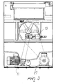
- the agitator apparatus comprises a supporting frame 1, inside which a flanged sleeve 2 is rigidly fixed; a hollow shaft 3 is in turn inserted in said sleeve and two sliding guides 4 are bolted thereto.
- the hollow shaft 3 is actuated by movement means 27 being conveniently constituted for example by an electric motor which turns the hollow shaft 3 by way of a belt-and-pulley transmission.
- Means 5 for the actuation of two arms 6 and 7 are suitable to move said arms along the guides 4 symmetrically with respect to the rotation of the hollow shaft 3.
- Said means for the actuation of the arms 6 and 7 are conveniently constituted, for example, by a right and left trapezoidal screw.
- the trapezoidal screw 5 is actuated by a bevel gear pair 8 having a shaft 9 which is provided, at one end, with a hexagonal hole for the engagement of a hexagonal shaft 10, being actuated by a pulley which is in turn actuated by a gearmotor 11.
- the pulley is designated by the reference numeral 12.
- the axis of motion of the bevel gear pair is parallel to the axis of the hollow shaft 3.
- the hexagonal shaft 10 moves axially in order to engage and disengage the shaft 9 of the bevel gear pair 8. Such axial movement is ensured by an electromagnet 13.
- the arms 6 and 7 each support a plate, designated by the reference numerals 15 and 14, respectively.
- At least one of the two plates, for example the plate 14, in the initial position is arranged downward and horizontally and can slide freely on a pair of guiding stems 16 so as to be extracted in order to facilitate the loading/unloading of the cans of lacquer.
- Stroke limiting means 28 allow to lock the lower plate 14 both in the extraction position for loading the can and in the retraction position for removing the can.
- the upper plate 15 is instead keyed to a pulley 17 which is driven by means of a belt (not shown) by another pulley 18 which is in turn keyed to another shaft 19 which has for example a hexagonal cross-section and to the end of which a bevel pinion 20 is rigidly fixed.
- the bevel pinion 20 meshes with a fixed bevel gear 21 which is bolted to the flanged sleeve 2.
- the upper plate 15 is fixed to a sliding shaft 24, and a cam 22 is arranged at the opposite end of said shaft 24 with respect to the plate; such cam is designed to excite sensor means 23, conveniently constituted for example by a proximity sensor.
- Motion is transmitted from the pulley 17 to the plate 15 when, under the action of a compression force, a shaft 25, which is coaxial to the shaft 24 and is rigidly coupled to the pulley 17, presses, together with the shaft 24, against a disk 26 of material having a high friction coefficient, which rigidly couples the two shafts.
- the operation of the agitator apparatus according to the invention is as follows.
- This operation occurs while the guides 4 are in a vertical position.
- the correct position is determined by a photosensor.
- the hexagonal shaft 10 is inserted in the hexagonal slot of the shaft 9 of the bevel gear pair 8 by virtue of the action of the electromagnet 13.
- the hexagonal shaft 10 starts to turn, actuated by the gearmotor 11, by way of the pulley 12.
- the motion is transmitted to the bevel gear pair 8, which turns the right and left trapezoidal screw 5, thereby closing or opening the arms 6 and 7.
- the arms close until the plates 14 and 15, with a symmetrical motion, abut against the opposite end surfaces of the can of lacquer or paint.
- the upper plate 15, under the compression action, performs a short vertical stroke with respect to its arm 6, so that the cam 22 excites the proximity microswitch 23.
- the microswitch provides the clearance signal indicating that a can of color is clamped between the two plates 14 and 15; thereafter, the hexagonal shaft 10 disengages from the shaft 9.
- the can has two simultaneous rotary motions: one with respect to the horizontal axis of the hollow shaft 3 and one with respect to the longitudinal axis of the can.
- the hollow shaft 3 ceases to turn and stops in the initial position again.
- the shaft 10 again engages the slot of the shaft 9 in order to act on the bevel gear pair 8 and open the plates 14 and 15, so as to allow to remove the can of lacquer or paint, whose content is by then perfectly mixed and amalgamated by the above described rotary motions.
- the can of lacquer or paint is turned exclusively in the presence of the clearance signal indicating that the arms 6 and 7, with the corresponding plates 15 and 14, have clamped around the can whose content is to be mixed.
- the sliding of the lower plate on the guides 16 allows to perform easy loading/unloading of the can of lacquer or paint to be processed.
- the apparatus according to the invention fully achieves the intended aim and objects, since it allows to move the can of lacquer or paint on two mutually perpendicular axes with simultaneous rotary motions in which the rotary motion about the axis of the hollow shaft of the agitator apparatus can be performed only when the arms of the apparatus have abutted against the opposite end surfaces of the can whose content is to be mixed.
- the materials used may be any according to requirements and to the state of the art.
Landscapes
- Chemical & Material Sciences (AREA)
- Chemical Kinetics & Catalysis (AREA)
- Mixers With Rotating Receptacles And Mixers With Vibration Mechanisms (AREA)
- Paints Or Removers (AREA)
- Mixers Of The Rotary Stirring Type (AREA)
- Accessories For Mixers (AREA)
- Coating Apparatus (AREA)
Abstract
Description
Claims (10)
- An agitator apparatus for mixing lacquers, paints and the like, characterized in that it comprises a supporting frame inside which a sleeve is fixed, said sleeve accommodating a hollow shaft being suitable to transmit a rotary motion, about its own axis, to two arms provided with respective plates which are suitable to abut against a can which contains lacquer or paint to be mixed; two sliding guides for said arms, arranged so as to be rigidly coupled to said hollow shaft; actuation means for the sliding of said arms along said two guides, which can be actuated when said hollow shaft is not rotating, said actuation means comprising screw means which are arranged parallel to said two guides and are actuated by a bevel gear pair which is in turn actuated by a first shaft, in which a second shaft is suitable to engage with an axial movement determined by the action of electromagnet means.
- The apparatus according to claim 1, characterized in that said first and second shafts are arranged so that their axes are parallel to the axis of said hollow shaft, said second shaft being actuated by a gearmotor.
- The apparatus according to claim 2, characterized in that it comprises means which are suitable to actuate said arms with a rotary motion about the axis of said can of lacquer or paint clamped between the respective plates of said arms.
- The apparatus according to one or more of the preceding claims, characterized in that said means for actuating the arms with a rotary motion about the axis of said can comprise additional screw means which have, at one end, a bevel pinion suitable to engage a bevel gear which is rigidly coupled to said sleeve, a first pulley being rigidly coupled to said additional screw means, a second pulley being rigidly coupled to one of said plates, for the transmission of the rotary motion of said additional screw means from said first pulley to said second pulley, and from said second pulley to said one of said plates.
- The apparatus according to one or more of the preceding claims, characterized in that the plate of said two plates that is suitable to be driven by said additional screw means is fixed to a sliding shaft, a cam element being arranged at the opposite end of said shaft respect to the plate, said cam element being suitable to excite a proximity sensor, an additional shaft being arranged coaxially to said sliding shaft and being suitable to be rigidly coupled to said sliding shaft by interposing a disk made of a material which has a high friction coefficient when said arm is pushed against the upper surface of said can.
- The apparatus according to one or more of the preceding claims, characterized in that said first pulley, which is rigidly coupled to said additional screw means, and said second pulley, on which said plate is keyed, are actuated by way of a belt.
- The apparatus according to one or more of the preceding claims, characterized in that it comprises at least one motor which is suitable to turn said hollow shaft.
- The apparatus according to one or more of the preceding claims, characterized in that said screw means comprise a right and left trapezoidal screw.
- The apparatus according to one or more of the preceding claims, characterized in that said first shaft of said means for the actuation of the two arms for opening/closure along said screw means has, at the opposite end with respect to the end where said bevel gear pair is provided, a slot allowing the engagement of said second shaft, which is hexagonal.
- The apparatus according to one or more of the preceding claims, characterized in that said sleeve is provided with a flange having a hole inside which said second shaft can slide freely in order to engage or disengage from said first shaft for the movement of said two arms along said guides.
Applications Claiming Priority (2)
| Application Number | Priority Date | Filing Date | Title |
|---|---|---|---|
| IT2000MI000208A ITMI20000208A1 (en) | 2000-02-09 | 2000-02-09 | STIRRING EQUIPMENT FOR MIXING PAINTS AND SIMILAR PAINTS |
| ITMI000208 | 2000-02-09 |
Publications (3)
| Publication Number | Publication Date |
|---|---|
| EP1123732A2 true EP1123732A2 (en) | 2001-08-16 |
| EP1123732A3 EP1123732A3 (en) | 2001-08-22 |
| EP1123732B1 EP1123732B1 (en) | 2003-04-23 |
Family
ID=11443947
Family Applications (1)
| Application Number | Title | Priority Date | Filing Date |
|---|---|---|---|
| EP01102152A Expired - Lifetime EP1123732B1 (en) | 2000-02-09 | 2001-02-01 | Agitator apparatus for mixing paints, lacquers and the like |
Country Status (4)
| Country | Link |
|---|---|
| EP (1) | EP1123732B1 (en) |
| AT (1) | ATE238097T1 (en) |
| DE (1) | DE60100196T2 (en) |
| IT (1) | ITMI20000208A1 (en) |
Cited By (11)
| Publication number | Priority date | Publication date | Assignee | Title |
|---|---|---|---|---|
| WO2003028872A1 (en) * | 2001-08-06 | 2003-04-10 | Cps Color Equipment S.P.A. | Protective structure for a clamping unit for clamping a container in a mixer for fluid products |
| WO2005009599A1 (en) * | 2003-07-24 | 2005-02-03 | Fluid Management, Inc. | Methods and apparatuses for mixing cosmetic preparations at a point of sale |
| WO2008095968A1 (en) * | 2007-02-08 | 2008-08-14 | Cps Color Equipment Spa Con Unico Socio | Anti-rotation device for a gripping member of a mixing machine for fluid products contained in a closed container |
| WO2009102860A3 (en) * | 2008-02-15 | 2009-10-29 | Red Devil Equipment Company | Gyroscopic mixer for mixing the content of individual paint containers |
| CN100595040C (en) * | 2004-06-30 | 2010-03-24 | 赛皮尔斯色料设备独资有限公司 | Clamping device for temporarily clamping a container containing a liquid product in a mixer and method for clamping the same |
| ITMI20120466A1 (en) * | 2012-03-23 | 2013-09-24 | Luigi Civardi | DEVICE TO MIX OR AMALGATE PAINTS, PAINTS OR THE LIKE |
| CN105417464A (en) * | 2015-12-05 | 2016-03-23 | 重庆市恒固席勒装饰工程有限公司 | Feeding device used for packaging oil paint |
| CN106422933A (en) * | 2016-08-31 | 2017-02-22 | 镇沅忠林现代农业科技发展有限公司 | Producing and processing equipment for organic fertilizer |
| CN107983238A (en) * | 2017-12-23 | 2018-05-04 | 郑州默尔电子信息技术有限公司 | A kind of screw slide block type multiple degrees of freedom building coating agitating device |
| CN108940103A (en) * | 2018-09-26 | 2018-12-07 | 晋江肯乐贸易有限公司 | A kind of machine core using efficient and uniformly mixed blender |
| CN116550184A (en) * | 2023-04-14 | 2023-08-08 | 濮阳市盛源能源科技股份有限公司 | An environment-friendly plasticizer production device |
Families Citing this family (2)
| Publication number | Priority date | Publication date | Assignee | Title |
|---|---|---|---|---|
| EP2377603B1 (en) * | 2010-04-16 | 2014-10-29 | Collomix Rühr-und Mischgeräte GmbH | Mixer, in particular biaxial mixer |
| CN111495264A (en) * | 2020-04-28 | 2020-08-07 | 临沂魅都家具有限公司 | Device for preventing stall of stirring device based on centrifugal force change |
Family Cites Families (6)
| Publication number | Priority date | Publication date | Assignee | Title |
|---|---|---|---|---|
| DE2809513C2 (en) * | 1978-03-06 | 1984-02-02 | Klaus H. Dipl.-Kaufm. 6102 Pfungstadt Krömmelbein | Device for mixing paints, varnishes, plaster or the like. |
| DE3111437C2 (en) * | 1981-03-24 | 1984-08-02 | Deutsche Amphibolin-Werke Von Robert Murjahn, 6105 Ober-Ramstadt | Centrifugal mixer |
| WO1991008045A1 (en) * | 1989-11-29 | 1991-06-13 | George Fethers & Co. Trading Pty. Ltd. | Mixing apparatus |
| DE9407810U1 (en) * | 1994-05-11 | 1994-07-28 | Collomix - Rühr- und Mischgeräte GmbH, 85080 Gaimersheim | Biaxial mixer |
| DE19611546C1 (en) * | 1996-03-23 | 1997-08-07 | Collomix Ruehr Mischgeraete | Biaxial mixer |
| ES2183286T3 (en) * | 1998-05-04 | 2003-03-16 | Meccanica Civardi S R L | MIXING MACHINE TO MIX VARNISHES, PAINTS AND SIMILAR. |
-
2000
- 2000-02-09 IT IT2000MI000208A patent/ITMI20000208A1/en unknown
-
2001
- 2001-02-01 DE DE60100196T patent/DE60100196T2/en not_active Expired - Fee Related
- 2001-02-01 AT AT01102152T patent/ATE238097T1/en not_active IP Right Cessation
- 2001-02-01 EP EP01102152A patent/EP1123732B1/en not_active Expired - Lifetime
Cited By (15)
| Publication number | Priority date | Publication date | Assignee | Title |
|---|---|---|---|---|
| WO2003028872A1 (en) * | 2001-08-06 | 2003-04-10 | Cps Color Equipment S.P.A. | Protective structure for a clamping unit for clamping a container in a mixer for fluid products |
| WO2005009599A1 (en) * | 2003-07-24 | 2005-02-03 | Fluid Management, Inc. | Methods and apparatuses for mixing cosmetic preparations at a point of sale |
| US7097348B2 (en) | 2003-07-24 | 2006-08-29 | Fluid Management, Inc. | Methods and apparatuses for mixing cosmetic preparations at a point of sale |
| CN100595040C (en) * | 2004-06-30 | 2010-03-24 | 赛皮尔斯色料设备独资有限公司 | Clamping device for temporarily clamping a container containing a liquid product in a mixer and method for clamping the same |
| WO2008095968A1 (en) * | 2007-02-08 | 2008-08-14 | Cps Color Equipment Spa Con Unico Socio | Anti-rotation device for a gripping member of a mixing machine for fluid products contained in a closed container |
| US8157436B2 (en) | 2008-02-15 | 2012-04-17 | Red Devil Equipment Company | Multi-size mixer |
| WO2009102860A3 (en) * | 2008-02-15 | 2009-10-29 | Red Devil Equipment Company | Gyroscopic mixer for mixing the content of individual paint containers |
| US8465199B2 (en) | 2008-02-15 | 2013-06-18 | Red Devil Equipment Co. | Multi-size mixer |
| US8905629B2 (en) | 2008-02-15 | 2014-12-09 | Red Devil Equipment Company | Multi-size mixer |
| ITMI20120466A1 (en) * | 2012-03-23 | 2013-09-24 | Luigi Civardi | DEVICE TO MIX OR AMALGATE PAINTS, PAINTS OR THE LIKE |
| CN105417464A (en) * | 2015-12-05 | 2016-03-23 | 重庆市恒固席勒装饰工程有限公司 | Feeding device used for packaging oil paint |
| CN106422933A (en) * | 2016-08-31 | 2017-02-22 | 镇沅忠林现代农业科技发展有限公司 | Producing and processing equipment for organic fertilizer |
| CN107983238A (en) * | 2017-12-23 | 2018-05-04 | 郑州默尔电子信息技术有限公司 | A kind of screw slide block type multiple degrees of freedom building coating agitating device |
| CN108940103A (en) * | 2018-09-26 | 2018-12-07 | 晋江肯乐贸易有限公司 | A kind of machine core using efficient and uniformly mixed blender |
| CN116550184A (en) * | 2023-04-14 | 2023-08-08 | 濮阳市盛源能源科技股份有限公司 | An environment-friendly plasticizer production device |
Also Published As
| Publication number | Publication date |
|---|---|
| ITMI20000208A0 (en) | 2000-02-09 |
| EP1123732B1 (en) | 2003-04-23 |
| ATE238097T1 (en) | 2003-05-15 |
| ITMI20000208A1 (en) | 2001-08-09 |
| DE60100196T2 (en) | 2004-02-26 |
| EP1123732A3 (en) | 2001-08-22 |
| DE60100196D1 (en) | 2003-05-28 |
Similar Documents
| Publication | Publication Date | Title |
|---|---|---|
| EP1123732B1 (en) | Agitator apparatus for mixing paints, lacquers and the like | |
| EP0779241B1 (en) | A perforating and plugging device for a machine for dispensing dyes or fluid products in general | |
| AU3257600A (en) | Food processing apparatus | |
| JPH01150064A (en) | Drive mechanism for intermittent shaft revolution at irregular interval | |
| CN110652906B (en) | Different-direction stirring and mixing method for chemical raw materials | |
| US5647140A (en) | Produce centrifugal spin drying apparatus | |
| US5662416A (en) | Automatic clamping apparatus for paint mixers | |
| CN117363871B (en) | Vertical shaft automatic quenching machine tool | |
| CN110585967B (en) | Coaxial anisotropic self-discharging type stirring equipment for promoting uniform mixing of chemical raw materials | |
| CN214565482U (en) | A kind of plate conveying device for construction machinery | |
| CN118858231A (en) | Quality testing equipment for PVC plastic particles | |
| CN116492899A (en) | Stirring equipment convenient for improving mixing efficiency and application method thereof | |
| JPH0532092B2 (en) | ||
| CN110652907B (en) | Adopt stirring subassembly that incorgruous stirring mode promoted industrial chemicals and mix | |
| CN118456141B (en) | A device for repairing inner-walled glass bottles | |
| CN220774315U (en) | Automatic opening and closing device for wafer box | |
| CN223836441U (en) | Discharging device for refractory material processing | |
| JPH0775512A (en) | Nori roll manufacturing equipment | |
| CN222342729U (en) | Printing ink agitator belt cleaning device | |
| KR102455687B1 (en) | Can Seamer | |
| US12397272B2 (en) | Multi-axis mixing | |
| CN223620416U (en) | Tempering furnace capable of preventing grinding balls from stacking | |
| CN112027148B (en) | Screw cap blanking assembly line for cup production | |
| KR200274281Y1 (en) | Automatic cooking machine | |
| CN222027313U (en) | Device suitable for processing dried leech |
Legal Events
| Date | Code | Title | Description |
|---|---|---|---|
| PUAI | Public reference made under article 153(3) epc to a published international application that has entered the european phase |
Free format text: ORIGINAL CODE: 0009012 |
|
| PUAL | Search report despatched |
Free format text: ORIGINAL CODE: 0009013 |
|
| AK | Designated contracting states |
Kind code of ref document: A2 Designated state(s): AT BE CH CY DE DK ES FI FR GB GR IE IT LI LU MC NL PT SE TR |
|
| AX | Request for extension of the european patent |
Free format text: AL;LT;LV;MK;RO;SI |
|
| AK | Designated contracting states |
Kind code of ref document: A3 Designated state(s): AT BE CH CY DE DK ES FI FR GB GR IE IT LI LU MC NL PT SE TR |
|
| AX | Request for extension of the european patent |
Free format text: AL;LT;LV;MK;RO;SI |
|
| 17P | Request for examination filed |
Effective date: 20020212 |
|
| AKX | Designation fees paid |
Free format text: AT BE CH CY DE DK ES FI FR GB GR IE IT LI LU MC NL PT SE TR |
|
| GRAH | Despatch of communication of intention to grant a patent |
Free format text: ORIGINAL CODE: EPIDOS IGRA |
|
| GRAH | Despatch of communication of intention to grant a patent |
Free format text: ORIGINAL CODE: EPIDOS IGRA |
|
| GRAA | (expected) grant |
Free format text: ORIGINAL CODE: 0009210 |
|
| AK | Designated contracting states |
Designated state(s): AT BE CH CY DE DK ES FI FR GB GR IE IT LI LU MC NL PT SE TR |
|
| PG25 | Lapsed in a contracting state [announced via postgrant information from national office to epo] |
Ref country code: TR Free format text: LAPSE BECAUSE OF FAILURE TO SUBMIT A TRANSLATION OF THE DESCRIPTION OR TO PAY THE FEE WITHIN THE PRESCRIBED TIME-LIMIT Effective date: 20030423 Ref country code: LI Free format text: LAPSE BECAUSE OF FAILURE TO SUBMIT A TRANSLATION OF THE DESCRIPTION OR TO PAY THE FEE WITHIN THE PRESCRIBED TIME-LIMIT Effective date: 20030423 Ref country code: FR Free format text: LAPSE BECAUSE OF FAILURE TO SUBMIT A TRANSLATION OF THE DESCRIPTION OR TO PAY THE FEE WITHIN THE PRESCRIBED TIME-LIMIT Effective date: 20030423 Ref country code: FI Free format text: LAPSE BECAUSE OF FAILURE TO SUBMIT A TRANSLATION OF THE DESCRIPTION OR TO PAY THE FEE WITHIN THE PRESCRIBED TIME-LIMIT Effective date: 20030423 Ref country code: CY Free format text: LAPSE BECAUSE OF FAILURE TO SUBMIT A TRANSLATION OF THE DESCRIPTION OR TO PAY THE FEE WITHIN THE PRESCRIBED TIME-LIMIT Effective date: 20030423 Ref country code: CH Free format text: LAPSE BECAUSE OF FAILURE TO SUBMIT A TRANSLATION OF THE DESCRIPTION OR TO PAY THE FEE WITHIN THE PRESCRIBED TIME-LIMIT Effective date: 20030423 Ref country code: BE Free format text: LAPSE BECAUSE OF FAILURE TO SUBMIT A TRANSLATION OF THE DESCRIPTION OR TO PAY THE FEE WITHIN THE PRESCRIBED TIME-LIMIT Effective date: 20030423 Ref country code: AT Free format text: LAPSE BECAUSE OF FAILURE TO SUBMIT A TRANSLATION OF THE DESCRIPTION OR TO PAY THE FEE WITHIN THE PRESCRIBED TIME-LIMIT Effective date: 20030423 |
|
| REG | Reference to a national code |
Ref country code: GB Ref legal event code: FG4D |
|
| REG | Reference to a national code |
Ref country code: CH Ref legal event code: EP |
|
| REF | Corresponds to: |
Ref document number: 60100196 Country of ref document: DE Date of ref document: 20030528 Kind code of ref document: P |
|
| REG | Reference to a national code |
Ref country code: IE Ref legal event code: FG4D |
|
| PG25 | Lapsed in a contracting state [announced via postgrant information from national office to epo] |
Ref country code: SE Free format text: LAPSE BECAUSE OF FAILURE TO SUBMIT A TRANSLATION OF THE DESCRIPTION OR TO PAY THE FEE WITHIN THE PRESCRIBED TIME-LIMIT Effective date: 20030723 Ref country code: PT Free format text: LAPSE BECAUSE OF FAILURE TO SUBMIT A TRANSLATION OF THE DESCRIPTION OR TO PAY THE FEE WITHIN THE PRESCRIBED TIME-LIMIT Effective date: 20030723 Ref country code: GR Free format text: LAPSE BECAUSE OF FAILURE TO SUBMIT A TRANSLATION OF THE DESCRIPTION OR TO PAY THE FEE WITHIN THE PRESCRIBED TIME-LIMIT Effective date: 20030723 Ref country code: DK Free format text: LAPSE BECAUSE OF FAILURE TO SUBMIT A TRANSLATION OF THE DESCRIPTION OR TO PAY THE FEE WITHIN THE PRESCRIBED TIME-LIMIT Effective date: 20030723 |
|
| PG25 | Lapsed in a contracting state [announced via postgrant information from national office to epo] |
Ref country code: ES Free format text: LAPSE BECAUSE OF FAILURE TO SUBMIT A TRANSLATION OF THE DESCRIPTION OR TO PAY THE FEE WITHIN THE PRESCRIBED TIME-LIMIT Effective date: 20031030 |
|
| REG | Reference to a national code |
Ref country code: CH Ref legal event code: PL |
|
| PG25 | Lapsed in a contracting state [announced via postgrant information from national office to epo] |
Ref country code: LU Free format text: LAPSE BECAUSE OF NON-PAYMENT OF DUE FEES Effective date: 20040201 |
|
| PLBE | No opposition filed within time limit |
Free format text: ORIGINAL CODE: 0009261 |
|
| STAA | Information on the status of an ep patent application or granted ep patent |
Free format text: STATUS: NO OPPOSITION FILED WITHIN TIME LIMIT |
|
| PG25 | Lapsed in a contracting state [announced via postgrant information from national office to epo] |
Ref country code: MC Free format text: LAPSE BECAUSE OF NON-PAYMENT OF DUE FEES Effective date: 20040228 |
|
| 26N | No opposition filed |
Effective date: 20040126 |
|
| EN | Fr: translation not filed | ||
| PG25 | Lapsed in a contracting state [announced via postgrant information from national office to epo] |
Ref country code: GB Free format text: LAPSE BECAUSE OF NON-PAYMENT OF DUE FEES Effective date: 20050201 |
|
| PGFP | Annual fee paid to national office [announced via postgrant information from national office to epo] |
Ref country code: IE Payment date: 20050208 Year of fee payment: 5 |
|
| PGFP | Annual fee paid to national office [announced via postgrant information from national office to epo] |
Ref country code: DE Payment date: 20050221 Year of fee payment: 5 |
|
| PGFP | Annual fee paid to national office [announced via postgrant information from national office to epo] |
Ref country code: NL Payment date: 20050224 Year of fee payment: 5 |
|
| GBPC | Gb: european patent ceased through non-payment of renewal fee |
Effective date: 20050201 |
|
| PG25 | Lapsed in a contracting state [announced via postgrant information from national office to epo] |
Ref country code: IE Free format text: LAPSE BECAUSE OF NON-PAYMENT OF DUE FEES Effective date: 20060201 |
|
| PGFP | Annual fee paid to national office [announced via postgrant information from national office to epo] |
Ref country code: IT Payment date: 20060228 Year of fee payment: 6 |
|
| PG25 | Lapsed in a contracting state [announced via postgrant information from national office to epo] |
Ref country code: NL Free format text: LAPSE BECAUSE OF NON-PAYMENT OF DUE FEES Effective date: 20060901 Ref country code: DE Free format text: LAPSE BECAUSE OF NON-PAYMENT OF DUE FEES Effective date: 20060901 |
|
| NLV4 | Nl: lapsed or anulled due to non-payment of the annual fee |
Effective date: 20060901 |
|
| REG | Reference to a national code |
Ref country code: IE Ref legal event code: MM4A |
|
| PG25 | Lapsed in a contracting state [announced via postgrant information from national office to epo] |
Ref country code: IT Free format text: LAPSE BECAUSE OF NON-PAYMENT OF DUE FEES Effective date: 20070201 |