EP1123745A1 - Distributeur verrouillable par gravité - Google Patents
Distributeur verrouillable par gravité Download PDFInfo
- Publication number
- EP1123745A1 EP1123745A1 EP20010103048 EP01103048A EP1123745A1 EP 1123745 A1 EP1123745 A1 EP 1123745A1 EP 20010103048 EP20010103048 EP 20010103048 EP 01103048 A EP01103048 A EP 01103048A EP 1123745 A1 EP1123745 A1 EP 1123745A1
- Authority
- EP
- European Patent Office
- Prior art keywords
- discharge device
- actuation
- housing
- actuating element
- stroke
- Prior art date
- Legal status (The legal status is an assumption and is not a legal conclusion. Google has not performed a legal analysis and makes no representation as to the accuracy of the status listed.)
- Granted
Links
- 230000005484 gravity Effects 0.000 title claims abstract description 7
- 230000000903 blocking effect Effects 0.000 claims description 13
- 239000004480 active ingredient Substances 0.000 claims description 5
- 239000012530 fluid Substances 0.000 claims description 5
- 230000001419 dependent effect Effects 0.000 claims description 4
- 238000005507 spraying Methods 0.000 claims description 3
- 125000006850 spacer group Chemical group 0.000 description 5
- 238000011109 contamination Methods 0.000 description 4
- 238000000034 method Methods 0.000 description 4
- 239000000463 material Substances 0.000 description 3
- 238000013461 design Methods 0.000 description 2
- 238000010586 diagram Methods 0.000 description 2
- 238000004519 manufacturing process Methods 0.000 description 2
- 230000008569 process Effects 0.000 description 2
- 238000007789 sealing Methods 0.000 description 2
- 241000894006 Bacteria Species 0.000 description 1
- 230000009471 action Effects 0.000 description 1
- 239000008186 active pharmaceutical agent Substances 0.000 description 1
- 239000013543 active substance Substances 0.000 description 1
- 230000008901 benefit Effects 0.000 description 1
- 230000015572 biosynthetic process Effects 0.000 description 1
- 239000003990 capacitor Substances 0.000 description 1
- 230000008859 change Effects 0.000 description 1
- 238000004891 communication Methods 0.000 description 1
- 230000006378 damage Effects 0.000 description 1
- 230000003247 decreasing effect Effects 0.000 description 1
- 238000011161 development Methods 0.000 description 1
- 230000018109 developmental process Effects 0.000 description 1
- 230000000694 effects Effects 0.000 description 1
- 230000005489 elastic deformation Effects 0.000 description 1
- 230000003993 interaction Effects 0.000 description 1
- 230000002427 irreversible effect Effects 0.000 description 1
- 238000012544 monitoring process Methods 0.000 description 1
- 238000000465 moulding Methods 0.000 description 1
- 230000003287 optical effect Effects 0.000 description 1
- 230000000284 resting effect Effects 0.000 description 1
- 238000012549 training Methods 0.000 description 1
Images



Classifications
-
- B—PERFORMING OPERATIONS; TRANSPORTING
- B05—SPRAYING OR ATOMISING IN GENERAL; APPLYING FLUENT MATERIALS TO SURFACES, IN GENERAL
- B05B—SPRAYING APPARATUS; ATOMISING APPARATUS; NOZZLES
- B05B12/00—Arrangements for controlling delivery; Arrangements for controlling the spray area
- B05B12/02—Arrangements for controlling delivery; Arrangements for controlling the spray area for controlling time, or sequence, of delivery
-
- A—HUMAN NECESSITIES
- A61—MEDICAL OR VETERINARY SCIENCE; HYGIENE
- A61M—DEVICES FOR INTRODUCING MEDIA INTO, OR ONTO, THE BODY; DEVICES FOR TRANSDUCING BODY MEDIA OR FOR TAKING MEDIA FROM THE BODY; DEVICES FOR PRODUCING OR ENDING SLEEP OR STUPOR
- A61M15/00—Inhalators
- A61M15/0065—Inhalators with dosage or measuring devices
-
- A—HUMAN NECESSITIES
- A61—MEDICAL OR VETERINARY SCIENCE; HYGIENE
- A61M—DEVICES FOR INTRODUCING MEDIA INTO, OR ONTO, THE BODY; DEVICES FOR TRANSDUCING BODY MEDIA OR FOR TAKING MEDIA FROM THE BODY; DEVICES FOR PRODUCING OR ENDING SLEEP OR STUPOR
- A61M15/00—Inhalators
- A61M15/0065—Inhalators with dosage or measuring devices
- A61M15/0068—Indicating or counting the number of dispensed doses or of remaining doses
- A61M15/0081—Locking means
-
- B—PERFORMING OPERATIONS; TRANSPORTING
- B05—SPRAYING OR ATOMISING IN GENERAL; APPLYING FLUENT MATERIALS TO SURFACES, IN GENERAL
- B05B—SPRAYING APPARATUS; ATOMISING APPARATUS; NOZZLES
- B05B11/00—Single-unit hand-held apparatus in which flow of contents is produced by the muscular force of the operator at the moment of use
- B05B11/0005—Components or details
- B05B11/0027—Means for neutralising the actuation of the sprayer ; Means for preventing access to the sprayer actuation means
-
- B—PERFORMING OPERATIONS; TRANSPORTING
- B65—CONVEYING; PACKING; STORING; HANDLING THIN OR FILAMENTARY MATERIAL
- B65D—CONTAINERS FOR STORAGE OR TRANSPORT OF ARTICLES OR MATERIALS, e.g. BAGS, BARRELS, BOTTLES, BOXES, CANS, CARTONS, CRATES, DRUMS, JARS, TANKS, HOPPERS, FORWARDING CONTAINERS; ACCESSORIES, CLOSURES, OR FITTINGS THEREFOR; PACKAGING ELEMENTS; PACKAGES
- B65D50/00—Closures with means for discouraging unauthorised opening or removal thereof, with or without indicating means, e.g. child-proof closures
- B65D50/02—Closures with means for discouraging unauthorised opening or removal thereof, with or without indicating means, e.g. child-proof closures openable or removable by the combination of plural actions
- B65D50/06—Closures with means for discouraging unauthorised opening or removal thereof, with or without indicating means, e.g. child-proof closures openable or removable by the combination of plural actions requiring the combination of different actions in succession
-
- B—PERFORMING OPERATIONS; TRANSPORTING
- B65—CONVEYING; PACKING; STORING; HANDLING THIN OR FILAMENTARY MATERIAL
- B65D—CONTAINERS FOR STORAGE OR TRANSPORT OF ARTICLES OR MATERIALS, e.g. BAGS, BARRELS, BOTTLES, BOXES, CANS, CARTONS, CRATES, DRUMS, JARS, TANKS, HOPPERS, FORWARDING CONTAINERS; ACCESSORIES, CLOSURES, OR FITTINGS THEREFOR; PACKAGING ELEMENTS; PACKAGES
- B65D83/00—Containers or packages with special means for dispensing contents
- B65D83/14—Containers for dispensing liquid or semi-liquid contents by internal gaseous pressure, i.e. aerosol containers comprising propellant
- B65D83/56—Containers for dispensing liquid or semi-liquid contents by internal gaseous pressure, i.e. aerosol containers comprising propellant with arrangements for interruption of dispensing when the container is inverted
-
- A—HUMAN NECESSITIES
- A61—MEDICAL OR VETERINARY SCIENCE; HYGIENE
- A61J—CONTAINERS SPECIALLY ADAPTED FOR MEDICAL OR PHARMACEUTICAL PURPOSES; DEVICES OR METHODS SPECIALLY ADAPTED FOR BRINGING PHARMACEUTICAL PRODUCTS INTO PARTICULAR PHYSICAL OR ADMINISTERING FORMS; DEVICES FOR ADMINISTERING FOOD OR MEDICINES ORALLY; BABY COMFORTERS; DEVICES FOR RECEIVING SPITTLE
- A61J7/00—Devices for administering medicines orally, e.g. spoons; Pill counting devices; Arrangements for time indication or reminder for taking medicine
- A61J7/04—Arrangements for time indication or reminder for taking medicine, e.g. programmed dispensers
- A61J7/0409—Arrangements for time indication or reminder for taking medicine, e.g. programmed dispensers with timers
- A61J7/0427—Arrangements for time indication or reminder for taking medicine, e.g. programmed dispensers with timers with direct interaction with a dispensing or delivery system
- A61J7/0445—Arrangements for time indication or reminder for taking medicine, e.g. programmed dispensers with timers with direct interaction with a dispensing or delivery system for preventing drug dispensing during a predetermined time period
-
- A—HUMAN NECESSITIES
- A61—MEDICAL OR VETERINARY SCIENCE; HYGIENE
- A61M—DEVICES FOR INTRODUCING MEDIA INTO, OR ONTO, THE BODY; DEVICES FOR TRANSDUCING BODY MEDIA OR FOR TAKING MEDIA FROM THE BODY; DEVICES FOR PRODUCING OR ENDING SLEEP OR STUPOR
- A61M2205/00—General characteristics of the apparatus
- A61M2205/21—General characteristics of the apparatus insensitive to tilting or inclination, e.g. spill-over prevention
- A61M2205/215—Tilt detection, e.g. for warning or shut-off
-
- A—HUMAN NECESSITIES
- A61—MEDICAL OR VETERINARY SCIENCE; HYGIENE
- A61M—DEVICES FOR INTRODUCING MEDIA INTO, OR ONTO, THE BODY; DEVICES FOR TRANSDUCING BODY MEDIA OR FOR TAKING MEDIA FROM THE BODY; DEVICES FOR PRODUCING OR ENDING SLEEP OR STUPOR
- A61M2205/00—General characteristics of the apparatus
- A61M2205/82—Internal energy supply devices
- A61M2205/8206—Internal energy supply devices battery-operated
-
- B—PERFORMING OPERATIONS; TRANSPORTING
- B05—SPRAYING OR ATOMISING IN GENERAL; APPLYING FLUENT MATERIALS TO SURFACES, IN GENERAL
- B05B—SPRAYING APPARATUS; ATOMISING APPARATUS; NOZZLES
- B05B11/00—Single-unit hand-held apparatus in which flow of contents is produced by the muscular force of the operator at the moment of use
- B05B11/01—Single-unit hand-held apparatus in which flow of contents is produced by the muscular force of the operator at the moment of use characterised by the means producing the flow
- B05B11/10—Pump arrangements for transferring the contents from the container to a pump chamber by a sucking effect and forcing the contents out through the dispensing nozzle
Definitions
- Discharge devices for media in particular for spraying one preferably at least one pharmaceutical Fluids containing active substance are general known.
- Such a discharge device based on the generic type goes for example from DE 197 53 147 A1 forth.
- Such a discharge device has a housing.
- An actuating element is relatively movable relative to the housing arranged. With every stroke of the actuator there is a discharge process, during each discharge process a certain amount of fluid from an arranged in the housing Container is carried out.
- the object of the invention is based on a generic to extend the discharge device so that it is possible, with every single actuation stroke to discharge the specified volume of medium.
- the object of the invention is based on a generic Discharge device by the characteristic Features of claim 1 solved.
- a discharge device for media has Housing on.
- An actuating element is arranged on the housing. Each time the actuating element is actuated an actuation stroke and thus the discharge of a certain volume of the medium stored in the housing.
- According to the invention are gravity-dependent locking devices designed so that it depends on the spatial location of the discharge device can block the execution of an actuation stroke.
- the Switching means are dependent on gravity switching blocking means movably mounted, mechanical switching means.
- the Switching means arranged so that under given spatial alignment of the discharge device, the switching means block an actuation stroke of the actuating element.
- the switching means are preferably balls guided in a curved path, the diameter of which advantageously is less than the path of an actuation stroke of the actuating element, preferably corresponds to the Diameter of a ball almost the path of an actuation stroke.
- the cam track has at least approximately the shape of an inclined plane.
- a configuration in which the cam track is preferred is also preferred at least one, defining a stop position, for receiving the ball has certain locking trough. More preferred it will be when the recess in the area of the cam track is arranged in which the ball has an actuation stroke the actuator blocks.
- the switching means are preferably designed so that they are each one-sided have a stop, on which the stop side of the switching means facing away from the actuation stroke of the Actuator locking position is formed and wherein a pair of switching means is provided, the Stop on opposite sides of the movement path are trained.
- the switching means are preferably one Couple aligned in a common direction and up opposite sides of the discharge device are formed.
- Locking means lock an actuation stroke if the deviation the discharge direction of the discharge device from the vertical exceeds an angle of at least 30 °, in particular 45 °.
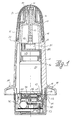
- FIG. 1 shows a discharge device in a partially sectioned illustration for media such as those used for spraying a fluid, preferably a pharmaceutical Contains active ingredient, can be used.
- the discharge device has a housing 11. In the case are closed to the outside, the functional elements arranged.
- the housing has to discharge the medium, in particular of a fluid, a discharge opening 12.
- a discharge opening 12 In order to contamination in the area of the discharge opening 12 and thus also a possible contamination or contamination with Bacteria is avoided as far as possible, the housing with the locked latching cap 20 placed on it.
- the closure cap 20 is made from an outer part 21 and an inner part 27 is formed. It remains between the lower edge of the closure cap 25 and the associated housing section a narrow gap 24. Otherwise forms housing 11 together with the cap 20 attached largely uniform and closed surface.
- the Outer part 21 of the closure cap also has the molded section, which here has the shape of a hollow cylinder and of arranged on the inside of the closed surface 23 of the outer part 21 and protrudes into the inner part 27 of the closure cap 20.
- the molded section 22 encloses the housing 11 in the area that contains and lies the discharge opening 12 in the area of the contact surface 26 on the housing. Thereby it is ensured that there is no outside air with the in the hollow cylindrical section of the mold section 22, the is closed by the sealing system 26 on the housing, can be exchanged. This will cause pollution or a contamination of the housing 11 in the region of the discharge opening 12 prevented.
- the inner part 27 of the closure cap 20th has a slide guide 28 for the sliding block 19, the Housing 11 is formed on. The backdrop is in this partially cut representation is not apparent.
- the case is open and is closed by the actuating element 50.
- the annular groove 15 formed in the housing in the when the immersed corresponding plunger 51 of the actuating element.
- the distance of an operating stroke of the operating element is the interaction between the depth of the Ring groove 15 of the housing 11 and the length of the plunge web 51st fixed to the actuator 50.
- the actuation stroke is limited by the invention that the plunger 51 abuts the bottom of the annular groove 15. In is not actuated position of the actuating element 50 therefore a gap between the actuating element 50 and the housing 11 available. This gap can be tamper-evident be closed, the predetermined breaking points and therefore is removable.
- the spacer 13 Is in position with the housing 11, leading to the discharge opening 12 and including the discharge channel, the spacer 13 arranged.
- the length of the spacer 13 is determined the space remaining in the housing 11 depending on the Size of the container 54. The larger the container 54 chosen becomes, the more operations of the actuators 50 can be done before container 54 is emptied is.
- the spacer 13 is fixed to the housing 11 arranged.
- the container 54 is fixed in position Actuator 50 arranged.
- the container 54 is by means of of the crimp ring 55 closed by the suction pump 56.
- the Piston tappet 57 of the suction pump 56 is designed so that he is in contact with the spacer 13, wherein a continuous one for the discharge of the medium to be discharged Channel through the piston tappet 57 and the spacer 13 is designed for the discharge opening 12.
- the container 54 is itself over the holder 53 engaging the crimp ring 55 attached to the support member 52.
- the support member 52 itself is again, at least indirectly, on the actuating element 50 attached.
- the guide ring 60 In the area of the lower end of the housing 11 through the stop surface 16 is formed is in the actuator 50, as a mechanically designed switching means of a gravitational switching locking means, the guide ring 60 arranged. There are several in the guide ring 60 in the shown example three each offset by 120 ° to each other Curved tracks 62 are introduced, in which a ball 61 is led. 1 is only a cam track 62 can be seen. The cam track 62 instructs the inner surface of the stop surface 66 on which in this Alignment of the discharge device, the ball 61 rests. In this position, the ball enables the execution an actuating stroke of the actuating element 50.
- the cam track has a ramp in shape in addition to its end stop 66 an inclined plane 63, which is opposite to the horizontal has the angle of inclination 64.
- This angle of inclination determines From what inclination of the discharge device the ball guided in the curved track 62 to roll on the ramp and finally to the other, outer end position, which is caused by the Detent depression 65 is formed, arrives.
- the ball 61 is held between the guide ring 60, the is firmly attached to the actuator 50 and the stop surface 16 of the housing 11. Since the diameter of the Ball at least almost the actuation path of an actuation stroke corresponds when the ball 61 is in this Position is locked, actuation of the actuating element.
- Cam tracks can be provided. If two cam tracks are provided, so these must be so trained that they are double-sided work, i.e. an inclination to the preferred direction, in which the discharge device should be aligned - mostly the vertical -, in one direction on both sides detected. It is only important that the cam tracks 62 Inclination in any direction from the preferred direction can capture, i.e. in at least two independent Dissolve directional components.
- control unit is also in the actuating element 50 70 arranged a time recording and a recording which includes actuations of the actuating element.
- the Control unit is able to lock member 74 between a release position 71 and a locking position back and forth to bring up. This is done by means of the electromagnet 75, which can be controlled by the control unit 70 and which on the locking member 74 can act.
- the figures 2a and 2b show a view of the actuating element 50 with that arranged in the actuating element 50 Actuation lock.
- the actuation lock is formed from the control unit 70, the electromagnet 75 and the locking member 74.
- these elements are on a common one Base plate 73 arranged, the base plate in Actuator 50 is preferably attached by latching becomes.
- FIG. 2a shows the locking member 74 in the release position 71 the actuation lock, while in Fig. 2b, the otherwise 2a corresponds to the locking member 74 in the Lock position 72 of the actuation lock.
- the energy supply which is not shown in the drawing is done via a battery, preferably a button cell or the like, and is for example below the base plate 73 arranged. With a capacitor, the energy supply be buffered, such as maintaining the storage values when changing the battery or a last actuation of the actuating element 50 after Allows failure of the battery supply.
- the Base plate 73 is preferably at the same time as a circuit board trained the corresponding electrical lines having. These include in particular the electrical connections between the control unit 70 and the electromagnet 75.
- the electromagnet 75 is also on the base plate 73 arranged. It acts on the locking member 74 trained magnetic body 77 a.
- the magnetic body 77 serves to this, under the influence of between the magnetic body 77 and the acting as a current relay electromagnet 75 acting electromagnetic forces a switching movement of the locking member 74 to generate.
- the locking member 74 is in the illustrated embodiment by pivoting around its Central axis from the release position 71 to the locked position and vice versa.
- a sectional drawing of the locking member 74 is in supervision and in side view in FIGS. 2c and 2d shown.
- FIG. 2e shows the view of the actuating element 50 from below, the outside of the housing of the actuating element 50.
- this On its bottom surface 58, this has the switch 78 on the one hand and on the other hand, the interface 79.
- the switch 78 Via the switch 78, in particular as a recessed key switch can be formed, the actuation, for example, only by means of an aid, preferably a pointed object, for example, a pencil tip can be arranged.
- the interface 79 is used to contact an information medium with the Control unit 70.
- the information medium can be either a passive component, in the simplest case one Contacting bridge or an input / output unit, such as a pc, act over the data, preferably parameters for the function of the control unit 70, can be transferred to this and also information from the control unit can be read out.
- the parameters that can be transmitted to the control unit 70 it is in particular the value of the first time interval, which begins when the actuating element is actuated and that defines the period before the the next time the actuator is actuated must be so that the actuation is not blocked.
- the second time interval as a parameter in the control unit 70 are transmitted.
- the second time interval is determined the time during which, after the switch 78 has been actuated predetermined number of actuations of the actuating element can be carried out without the actuation lock engaging. Likewise, this number of operations without Intervention of the actuation lock after actuation of the switch 78 can be carried out, can be specified via the interface 79.
- the interface 79 can therefore in particular be a Plug connection of a data bus for the control unit 70 act. Two-wire data buses are preferred as the data bus into consideration. It is also possible to use the interface 79 also read out information from the control unit 70. For example, the number of successes Actuation strokes and the number of actuations of the switch 78 are recorded.
- the information element can also just a contact bridge for electrical contacting between the two individual strands connected to the interface 79 end, be trained.
- the contact bridge is preferably located in the form of a specially shaped plug, for example only to a limited group of people, such as nurses and pharmacist, is spent. Will the presence the jumper plug at interface 79, if the switch 78 is actuated, it can in this way ensure that no unauthorized persons have a number of Can actuate the actuating element 50, without the actuation lock engaging. This is a measure in terms of increasing operator safety. This can but make it necessary that the first commissioning of the Dispenser also by an authorized person must be done.
- the figures 2c and 2d show the top view and the side view of the locking member 74.
- the locking member 74 has in its center 82 has the shape of a disk that extends around the central axis 80 is rotatably mounted.
- the Holding arm 83 which at its end for receiving the contact piece 84 is formed and also the permanent magnet body 77 towards the outside.
- Opposite of magnetic body 77 and Holding arm 83 is the balancing mass 85 formed for an at least approximate balancing of the locking member 74 with respect to the central axis 80 and thus an easy operability the locking member 74 provides.
- Blocking body 89 formed.
- the locking body protrude parallel to the central axis 80 in the actuating element 50 above, out of the plane of the locking member 74 the height of the locking body 89 the path of an actuation stroke of the actuator 50.
- the release position 71 of the locking member 74 it is possible, for example in a guide groove, the locking body 89 in the housing 11 lead in.
- the locked position 72 are the Locking body 89 in a position in which it the space between the lower end of the housing 11 with its stop surface 16 and a correspondingly trained surface Fill in on the actuator. This will cause a move of the actuator around the path of the actuation stroke Discharge device blocked. This is an actuation of the Discharge device impossible.
- a Discharge device as used here in particular So a pump atomizer has a certain free travel.
- Around the blocking bodies 98 can be shorter than this free travel than the way of the operating stroke of the operating member 50.
- the locking member 74 is pivoted about the central axis 80 in the blocking position 72 and back again in the release position 71 procedure. This movement is, at least so far the locking bodies are not held in a force-fitting manner in the housing be, for example, when a person the actuator 50 operated and the locking body 89 in his Locked position 72 is done almost without force. Therefore an electromagnet that generates low forces is sufficient to very quickly the switching position of the locking member 74th to change. It is not a big effort and also no great energy expenditure required.
- can switching takes place in the short period in which the Free travel of the actuating element 50 when actuated is covered. Then it is also in a resting position monostable in the release position 71 locking member 74 energy-saving possible by brief actuation of the electromagnet to generate the blocking position.
- the figures 3a and 3b show from two different perspectives a view of the inner part 27 of the cap 20.
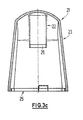
- the closure cap 20 is formed from the inner part 27 and the outer part 21 shown in FIG. 3c.
- the inner part 27 is formed from a base body 31.
- the base body 31 carries all trained for the function of the cap Elements.
- To train the backdrop guide 28 for the sliding block 19 located on the housing is a free space 31 intended.
- the free space 31 leads past a web. After this the web has been run over, it is possible to close the cap through an angle - which is preferably less than 90 ° is -, in the example shown, the angle is approximately 20 °, to twist. Then the sliding block can "fall" into the trough 32.
- the sliding block 19 In the trough 32, the sliding block 19 is held so that a twisting of the cap itself directly from this Location is not possible. So that the sliding block 19 safely in the Trough 32 elongated, the energy accumulator is on the inner part 27 29 designed in the form of a bendable material element. This material element is elastic in the region of the shaft 34 deformable.
- the head 35 projects into the interior of the inner part. It comes into contact with the housing 11. Because the inside of the head is also beveled is how the housing 11 is chamfered in this area, the head is pushed outwards, which creates a force is when the inner part or the cap on the Housing 11 is placed.
- the bevel then causes when no more force is exerted on the closure cap 20 acts, the elastic deformation has a tendency to recede and this force, which is supported on the housing, the Cap in the release direction on the housing 11 upwards pushes.
- the active element 30 is formed.
- the active element 30 is also a web of material that is elastic within certain limits is deformable. The active element 30 turns when the Cap on the housing in contact with the non-circular shape Housing 11. During twisting this will Active element 30 pressed outwards and slightly elastic deformed. This counteracts the opening of the closure cap Strength built.
- one must be determined Force must be applied to the cap put on the housing. This serves for operational safety, that the user of the discharge device is forced Apply a minimum force when opening and also when closing the housing with the closure cap a force is applied.
- Link guides 28 and force storage 29 in between and / or active element 30 are advantageously on two opposite sides Link guides 28 and force storage 29 in between and / or active element 30.
- Closure cap from the inner part 27 and from the outer part 21 to manufacture It is simple for manufacturing reasons that Closure cap from the inner part 27 and from the outer part 21 to manufacture. It is also possible to have only a one-piece cap to provide, but then shaped more complicated is or is not consistently closed to the outside has a smooth surface.
- the outer part 21 has a closed smooth outer surface 23. Inside of the outer part 21, the inner part 27 is inserted and there attached positively or non-positively. Furthermore, the interior points of the outer part 21 still designed as a hollow cylinder Molding section 22. The shaped section 22 abuts with a End to the inside of the closed area 23. At his the other end, the sealing system 26 is formed, the abuts the housing 11 so that the discharge opening 12 is enclosed.
- the lower edge is on the outer part 21 25 trained. At the lower edge 25, when on Housing 11 patch cap, one in the drawing Support the mandrel, not shown.
- the thorn is through an opening 11 provided in the housing is brought out and fixed connected to the actuator 50. This measure prevents that an actuation of the actuator 50 at closed cap is done. This increases security and prevents especially in cooperation with the timeout during the first time interval after a Operation of the actuator 50, the operational safety. An actuation of the actuating element 50 is only possible when the cap has been removed.
- the figures 4a and 4b show in two different positions the function of the guide ring 60.
- the guide ring 60 is attached to the actuator 50 and in the area thereof the upper end, that is, the housing end.
- the Housing 11 has the annular groove 15 into which the plunger web 51 of the actuating element 50 is immersed during an actuation.
- the guide ring 60 is arranged so that the Cam track 62 for the ball guided in the cam track 62 61 opens on the outside of the actuating element 50 and indeed immediately below the stop surface 16 on the housing 11.
- the stop surface 16 can be shaped so that it takes over part of the guidance of the ball 61 in the guideway.
- FIG. 4a shows the situation in which the discharge device is in a position in which discharge is possible should be. This is preferably desired when the discharge device no more than a predetermined Angle, which is preferably in a range between 30 and 35 ° lies inclined with respect to the vertical (as preferred direction) is.
- the ball 61 is in the cam track 62 of the guide ring 60 led.
- the cam track 62 has an inclined plane 63 on, so that the ball 61 is in an almost vertical position inside end stop 66 is located. Is in this position it possible an actuation stroke of the actuating element perform. To do this, only the actuator has to Actuating path can be moved relative to the housing 11.
- the ball rolls in the curved path 62. It rolls until it reaches the outer end of the Cam track has arrived and strikes the actuating element 50. It is then in the recess 65, which is on the cam track 62 is formed, held. It is now between the recess 65, ie the guide ring 60 and the formed by the housing 11 stop surface 16. Da the ball 61 has a diameter that is approximately the path corresponds to an actuation stroke, it blocks the implementation an actuation stroke, since the required clearance between the recess 65 and the stop surface 16 through the ball is filled out. Thus, an actuation of the actuating element 50 prevented as long as the inclination of the discharge device not within the preferred direction a predetermined angular position.
- the blocking position of the Ball 61 is shown in Fig. 4b.
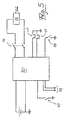
- Fig. 5 shows the circuit diagram for an inventive Discharge device for media with an actuation lock, which can be controlled by a control unit.
- the electromagnet 75 is arranged and can be controlled by the control unit 70.
- control unit When the control unit is powered for the first time is, so a battery for power supply on the part of the actuator is installed, or by the user Contact protection from the battery or the contact elements make electrical contact with the battery the control unit allows the execution of a predetermined number of operations of the actuating element 50 without an actuation lock taking effect. These operations are used to initialize the discharge device in the way already described.
- the actuation of an actuating element is via the Dosing sensor 40 detects.
- This dosing sensor is in the actuator 50 arranged that an actuation of the actuating element 50 is detected, which exceeds a certain level.
- the sensor is preferably a switch or Pushbutton switch formed by changing the relative position switched between actuator 50 and housing 11 becomes.
- the metering sensor becomes 40 actuated, a corresponding switching signal is in the Control unit 70 generated. Then it is checked whether since the previous actuation of the actuating element 50 at least a predetermined time interval has been exceeded. If this is not the case, the electromagnet will do so activated that the actuation lock with its locking member 74 is brought into the blocking position 72. Otherwise the relay is driven so that the locking member 74 in the Release position 71 is spent. If an actuation of the Actuator 50 allows, the same time Time counter for monitoring the time interval since last actuation of the discharge device again to zero reset. Surveillance can of course also include a time counter that does not discriminate, but decriminalized back to zero. Simultaneously with the spending of the locking member 74 in the release position 71 or Lock position 72 can be an alarm signal via a signal generator be generated. The signal is preferably an acoustic one Signal.
- This procedure corresponds to the formation of the locking member 74 as a bistable element. But is this as monostable Element formed and for example by an energy store either in the locked position 72 or the release position 71 held, the electromagnet must be actuated only take place when the blocking element is switched should be done.
- a bias of the monostable locking member 74 in the Release position 71 has the advantage that if the Electronics a discharge by actuating the actuating element 50 can take place, but then an uncontrolled, disregarding the interval of the first time interval Discharge is possible.
- pre-tensioning the monostable prevents Locking member 74 in the locking position 72 this uncontrolled Discharge in the event of an error, but then is also a the first time interval due to the blocking position 72 of the locking member 74 impossible.
- mechanical means removable Securing element
- the release position 71 or the locking position 72 of the locking member 74 is detected by the control sensors 41.
- the control sensors 41 become from the first and second pairs of contact pins formed, which contacts the contact piece 84 and so grasp the situation.
- Via the switch 78 can a new start can be generated with the given Number of operations of the actuator 50 without intervention the actuation lock can be carried out.
- about the interface 79 can also be connected to the control unit accessed and data communication carried out.
- the parameters of the control unit 70 can be set and recorded data on the use of the Discharge device can be read out.
Landscapes
- Health & Medical Sciences (AREA)
- Engineering & Computer Science (AREA)
- Life Sciences & Earth Sciences (AREA)
- Biomedical Technology (AREA)
- Hematology (AREA)
- Biophysics (AREA)
- Veterinary Medicine (AREA)
- Bioinformatics & Cheminformatics (AREA)
- Pulmonology (AREA)
- Anesthesiology (AREA)
- Public Health (AREA)
- Heart & Thoracic Surgery (AREA)
- Mechanical Engineering (AREA)
- Animal Behavior & Ethology (AREA)
- General Health & Medical Sciences (AREA)
- Chemical & Material Sciences (AREA)
- Dispersion Chemistry (AREA)
- Infusion, Injection, And Reservoir Apparatuses (AREA)
- Containers And Packaging Bodies Having A Special Means To Remove Contents (AREA)
- Closures For Containers (AREA)
Applications Claiming Priority (3)
| Application Number | Priority Date | Filing Date | Title |
|---|---|---|---|
| DE10006370A DE10006370A1 (de) | 2000-02-12 | 2000-02-12 | Austragvorrichtung für Medien |
| DE10006368 | 2000-02-12 | ||
| DE2000106368 DE10006368A1 (de) | 2000-02-12 | 2000-02-12 | Austragvorrichtung für Medien |
Publications (2)
| Publication Number | Publication Date |
|---|---|
| EP1123745A1 true EP1123745A1 (fr) | 2001-08-16 |
| EP1123745B1 EP1123745B1 (fr) | 2008-12-10 |
Family
ID=65728958
Family Applications (2)
| Application Number | Title | Priority Date | Filing Date |
|---|---|---|---|
| EP20010103048 Expired - Lifetime EP1123745B1 (fr) | 2000-02-12 | 2001-02-09 | Distributeur verrouillable par gravité |
| EP01103047A Withdrawn EP1123873A3 (fr) | 2000-02-12 | 2001-02-09 | Distributeur à sécurité pour enfants |
Family Applications After (1)
| Application Number | Title | Priority Date | Filing Date |
|---|---|---|---|
| EP01103047A Withdrawn EP1123873A3 (fr) | 2000-02-12 | 2001-02-09 | Distributeur à sécurité pour enfants |
Country Status (3)
| Country | Link |
|---|---|
| US (2) | US20010016701A1 (fr) |
| EP (2) | EP1123745B1 (fr) |
| DE (3) | DE10006368A1 (fr) |
Cited By (2)
| Publication number | Priority date | Publication date | Assignee | Title |
|---|---|---|---|---|
| WO2007099044A1 (fr) | 2006-03-03 | 2007-09-07 | Shl Medical Ab | Appareil médical avec mécanisme d'amorce sensible à l'orientation |
| WO2013037925A1 (fr) | 2011-09-15 | 2013-03-21 | L'oreal | Distributeur de produit cosmétique et récipient associé |
Families Citing this family (41)
| Publication number | Priority date | Publication date | Assignee | Title |
|---|---|---|---|---|
| US7743765B2 (en) * | 1997-11-14 | 2010-06-29 | Astrazeneca Ab | Inhalation device |
| SE9704185D0 (sv) * | 1997-11-14 | 1997-11-14 | Astra Pharma Prod | Inhalation device |
| US7967011B2 (en) * | 1997-11-14 | 2011-06-28 | Astrazeneca Ab | Inhalation device |
| US20060213505A1 (en) * | 1997-11-14 | 2006-09-28 | Astrazeneca Ab | Inhalation device |
| DE10050982A1 (de) * | 2000-10-16 | 2002-04-18 | Pfeiffer Erich Gmbh & Co Kg | Spender und Verfahren zum Austragen von Medien |
| FR2835812B1 (fr) * | 2002-02-12 | 2004-07-30 | Techniplast | Dispositif de distribution protege contre un fonctionnement accidentel |
| DE202004002024U1 (de) * | 2003-11-18 | 2005-04-07 | Kiepe Thomas | Verpackung |
| US11590286B2 (en) | 2004-11-22 | 2023-02-28 | Kaleo, Inc. | Devices, systems and methods for medicament delivery |
| US10737028B2 (en) | 2004-11-22 | 2020-08-11 | Kaleo, Inc. | Devices, systems and methods for medicament delivery |
| US9022980B2 (en) | 2005-02-01 | 2015-05-05 | Kaleo, Inc. | Medical injector simulation device |
| DK2058020T3 (da) | 2005-02-01 | 2013-01-07 | Intelliject Inc | Indretning til indgivelse af lægemiddel |
| US8206360B2 (en) | 2005-02-01 | 2012-06-26 | Intelliject, Inc. | Devices, systems and methods for medicament delivery |
| GB0520645D0 (en) * | 2005-10-11 | 2005-11-16 | Jagotec Ag | Gravity-actuated locking mechanism for drug container |
| US7726520B2 (en) * | 2005-12-22 | 2010-06-01 | Innopak Inc. | Metered dispenser with feed-containing piston drive mechanism |
| GB0602897D0 (en) * | 2006-02-13 | 2006-03-22 | Jagotec Ag | Improvements In Or Relating To Dry Powder Inhaler Devices |
| WO2008008281A2 (fr) | 2006-07-07 | 2008-01-17 | Proteus Biomedical, Inc. | Système d'administration parentérale intelligent |
| JP5055281B2 (ja) * | 2006-08-11 | 2012-10-24 | テイカ製薬株式会社 | 点眼薬容器 |
| US20080058772A1 (en) * | 2006-08-31 | 2008-03-06 | Robertson Timothy L | Personal paramedic |
| GB0625303D0 (en) * | 2006-12-19 | 2007-01-24 | Jagotec Ag | Improvements in and relating to metered dose inhalers |
| WO2009055733A1 (fr) | 2007-10-25 | 2009-04-30 | Proteus Biomedical, Inc. | Système d'informations d'orifice de transfert de fluide |
| WO2009067463A1 (fr) | 2007-11-19 | 2009-05-28 | Proteus Biomedical, Inc. | Dispositifs d'évaluation de structures de transport de fluides associées au corps |
| DE102007056380B4 (de) * | 2007-11-22 | 2020-06-25 | WestRock Dispensing Systems Hemer GmbH | Verschlusskappe für einen Austragkopf |
| US8021344B2 (en) | 2008-07-28 | 2011-09-20 | Intelliject, Inc. | Medicament delivery device configured to produce an audible output |
| USD994111S1 (en) | 2008-05-12 | 2023-08-01 | Kaleo, Inc. | Medicament delivery device cover |
| DE102008027147A1 (de) | 2008-06-02 | 2009-12-03 | Ing. Erich Pfeiffer Gmbh | Austragvorrichtung für Medien |
| US8109414B2 (en) * | 2008-10-07 | 2012-02-07 | Ing. Erich Pfeiffer Gmbh | Discharge device |
| BR112012019212A2 (pt) | 2010-02-01 | 2017-06-13 | Proteus Digital Health Inc | sistema de coleta de dados |
| US8332020B2 (en) | 2010-02-01 | 2012-12-11 | Proteus Digital Health, Inc. | Two-wrist data gathering system |
| US9173999B2 (en) | 2011-01-26 | 2015-11-03 | Kaleo, Inc. | Devices and methods for delivering medicaments from a multi-chamber container |
| US9446414B2 (en) * | 2011-07-27 | 2016-09-20 | Bandit Industries, Inc. | Waste processing machine, vigilance control system, timer, and methods therefor |
| GB2526948A (en) | 2012-12-27 | 2015-12-09 | Kaleo Inc | Systems for locating and interacting with medicament delivery devices |
| EP3274021B1 (fr) | 2015-03-24 | 2024-02-14 | Kaleo, Inc. | Dispositifs et procédés pour administrer un médicament lyophilisé |
| AU2016287571C1 (en) | 2015-06-30 | 2021-12-23 | Kaleo, Inc. | Auto-injectors for administration of a medicament within a prefilled syringe |
| WO2018119218A1 (fr) | 2016-12-23 | 2018-06-28 | Kaleo, Inc. | Dispositif d'administration de médicament et procédés d'administration de médicaments à des nourrissons et des enfants |
| WO2018136413A2 (fr) | 2017-01-17 | 2018-07-26 | Kaleo, Inc. | Dispositifs d'administration de médicament à connectivité sans fil et à détection d'événement |
| JP7378436B2 (ja) * | 2018-06-25 | 2023-11-13 | サノフイ | 薬剤送達デバイス |
| WO2020018433A1 (fr) | 2018-07-16 | 2020-01-23 | Kaleo, Inc. | Dispositif d'administration de médicaments à connectivité sans fil et à détection de conformité |
| EP3902584A4 (fr) | 2018-12-29 | 2022-09-07 | Kaleo, Inc. | Dispositifs et procédés de distribution de substances dans une seringue pré-remplie |
| EP3769852A1 (fr) * | 2019-07-22 | 2021-01-27 | Open Innovation 2 Go, SL | Distributeur actionné par une pompe avec commutateur intégré, système et procédé de surveillance à distance de la consommation de produit à partir dudit distributeur actionné par une pompe |
| US11167087B2 (en) | 2019-08-09 | 2021-11-09 | Kaleo, Inc. | Devices and methods for delivery of substances within a prefilled syringe |
| US12268847B1 (en) | 2021-02-10 | 2025-04-08 | Kaleo, Inc. | Devices and methods for delivery of substances within a medicament container |
Citations (6)
| Publication number | Priority date | Publication date | Assignee | Title |
|---|---|---|---|---|
| US2954904A (en) * | 1958-10-13 | 1960-10-04 | Joseph B Potoczky | Gas pressure type dispensing container cap |
| FR2152479A1 (fr) * | 1971-09-17 | 1973-04-27 | Oreal | |
| US4969584A (en) * | 1988-10-13 | 1990-11-13 | L'oreal | Pressurized container including a system for blocking the valve when the container is not in a proper position |
| US5038964A (en) * | 1988-05-10 | 1991-08-13 | L'oreal | Pressurized container including a valve and a device for actuating the valve |
| WO1998055378A1 (fr) * | 1997-06-05 | 1998-12-10 | The Procter & Gamble Company | Buse pour recipients sous pression |
| EP0938933A2 (fr) * | 1998-02-25 | 1999-09-01 | Ing. Erich Pfeiffer Gmbh | Commande de la décharge pour un distributeur de fluide |
Family Cites Families (25)
| Publication number | Priority date | Publication date | Assignee | Title |
|---|---|---|---|---|
| DE419886C (de) * | 1925-10-13 | Wilhelm Cassens | Kannenverschluss | |
| BE754680A (fr) * | 1969-08-18 | 1971-01-18 | Markowitz Isral J | Bouchon de securite pour bombe |
| US3706401A (en) * | 1970-07-15 | 1972-12-19 | Sunbeam Plastics Corp | Child-proof overcap for an aerosol can |
| GB1362492A (en) * | 1971-07-01 | 1974-08-07 | Reflex Corp Canada Ltd | Safety cap adaptor for containers |
| US3927783A (en) * | 1974-01-28 | 1975-12-23 | Clayton Bogert | Safety closure for containers |
| CA1077001A (fr) * | 1976-10-21 | 1980-05-06 | Winfried J. Werding | Appareil servant a l'evacuation de produits gazeux, liquides ou pateux, et procede de fabrication |
| US4156489A (en) * | 1978-07-14 | 1979-05-29 | Kong Cheung T | Cap and container in combination with a safety locking means |
| DK148406C (da) * | 1980-07-15 | 1985-12-09 | Johannes Saemundur Palsson | Beholder med sikkerhedslukke |
| DE3102524A1 (de) * | 1981-01-27 | 1982-09-16 | Eberhard 3354 Dassel Krüger | Aerosol-spruehdosenverschlusskappe |
| US4871092A (en) * | 1982-07-10 | 1989-10-03 | Ing. Erich Pfeiffer Gmbh & Co. Kg | Atomizing or metering pump |
| US4553678A (en) * | 1984-06-21 | 1985-11-19 | Thorsbakken Arden L | Tamper indicating container safety cover |
| DE8526339U1 (de) | 1985-09-14 | 1987-05-07 | Ing. Erich Pfeiffer GmbH & Co KG, 7760 Radolfzell | Austragvorrichtung für fließfähige Medien |
| DE3544985A1 (de) * | 1985-12-19 | 1987-06-25 | Pfeiffer Erich Gmbh & Co Kg | Austragvorrichtung fuer fliessfaehige medien |
| US4944429A (en) * | 1987-08-28 | 1990-07-31 | Schering Corporation | Manually-operable spray dispenser with locking mechanism |
| FR2657795B1 (fr) * | 1990-02-05 | 1992-05-07 | Fouche Bernard | Dispositif mecanique commande par un allumeur pyro-electrique pour diffuser un produit contenu dans un aerosol. |
| DE4005528C2 (de) * | 1990-02-22 | 1998-01-15 | Pfeiffer Erich Gmbh & Co Kg | Austragvorrichtung für Medien |
| FR2697506B1 (fr) * | 1992-10-30 | 1994-12-30 | Reboul Smt | Conditionnement à fermeture rapide. |
| US5462186A (en) * | 1994-08-02 | 1995-10-31 | The Coca Cola Company | Cam follower closure on container with cam track finish |
| DE4447087A1 (de) * | 1994-12-29 | 1996-07-04 | Friedrich Beutelspacher | Sprühbehälter, der in jeder Raumlage funktionsfähig ist |
| US5566845A (en) * | 1995-02-01 | 1996-10-22 | Idea Laboratories, Inc. | Container having a seal puncturing device |
| WO1996023705A1 (fr) * | 1995-02-01 | 1996-08-08 | Idea Laboratories | Contenant a l'epreuve des enfants |
| EP0751078B1 (fr) * | 1995-06-28 | 2001-11-14 | The Procter & Gamble Company | Emballage de protection vis-à-vis des enfants, mais facile à manipuler pour les adultes |
| DE19753147A1 (de) * | 1997-11-29 | 1999-06-02 | Pfeiffer Erich Gmbh & Co Kg | Spender mit manuell betätigbarer Ausbringeinrichtung |
| US6202876B1 (en) * | 1998-12-30 | 2001-03-20 | Primary Delivery Systems, Inc. | Push and twist locking child-resistant and container |
| FR2801569B1 (fr) * | 1999-11-29 | 2002-04-26 | Valois Sa | Capuchon de securite |
-
2000
- 2000-02-12 DE DE2000106368 patent/DE10006368A1/de not_active Withdrawn
- 2000-02-12 DE DE10006370A patent/DE10006370A1/de not_active Withdrawn
-
2001
- 2001-02-09 EP EP20010103048 patent/EP1123745B1/fr not_active Expired - Lifetime
- 2001-02-09 DE DE50114552T patent/DE50114552D1/de not_active Expired - Lifetime
- 2001-02-09 US US09/780,932 patent/US20010016701A1/en not_active Abandoned
- 2001-02-09 US US09/780,856 patent/US6427684B2/en not_active Expired - Lifetime
- 2001-02-09 EP EP01103047A patent/EP1123873A3/fr not_active Withdrawn
Patent Citations (6)
| Publication number | Priority date | Publication date | Assignee | Title |
|---|---|---|---|---|
| US2954904A (en) * | 1958-10-13 | 1960-10-04 | Joseph B Potoczky | Gas pressure type dispensing container cap |
| FR2152479A1 (fr) * | 1971-09-17 | 1973-04-27 | Oreal | |
| US5038964A (en) * | 1988-05-10 | 1991-08-13 | L'oreal | Pressurized container including a valve and a device for actuating the valve |
| US4969584A (en) * | 1988-10-13 | 1990-11-13 | L'oreal | Pressurized container including a system for blocking the valve when the container is not in a proper position |
| WO1998055378A1 (fr) * | 1997-06-05 | 1998-12-10 | The Procter & Gamble Company | Buse pour recipients sous pression |
| EP0938933A2 (fr) * | 1998-02-25 | 1999-09-01 | Ing. Erich Pfeiffer Gmbh | Commande de la décharge pour un distributeur de fluide |
Cited By (2)
| Publication number | Priority date | Publication date | Assignee | Title |
|---|---|---|---|---|
| WO2007099044A1 (fr) | 2006-03-03 | 2007-09-07 | Shl Medical Ab | Appareil médical avec mécanisme d'amorce sensible à l'orientation |
| WO2013037925A1 (fr) | 2011-09-15 | 2013-03-21 | L'oreal | Distributeur de produit cosmétique et récipient associé |
Also Published As
| Publication number | Publication date |
|---|---|
| US20010016701A1 (en) | 2001-08-23 |
| EP1123873A3 (fr) | 2003-09-24 |
| EP1123873A2 (fr) | 2001-08-16 |
| EP1123745B1 (fr) | 2008-12-10 |
| US6427684B2 (en) | 2002-08-06 |
| DE10006370A1 (de) | 2001-08-16 |
| US20010013525A1 (en) | 2001-08-16 |
| DE50114552D1 (de) | 2009-01-22 |
| DE10006368A1 (de) | 2001-08-16 |
Similar Documents
| Publication | Publication Date | Title |
|---|---|---|
| EP1123745B1 (fr) | Distributeur verrouillable par gravité | |
| EP1125637B1 (fr) | Distributeur de fluides | |
| DE60123646T2 (de) | Sicheres verteilungsgerät | |
| EP1084763B1 (fr) | Distributeur, notamment pour pulvériser un produit fluide contenu dans un réservoir | |
| DE60111501T2 (de) | Spritzen und spritzsysteme zur selektiven verabreichung von kontrollierten mengen einer therapeutischen substanz | |
| DE69607015T2 (de) | Inhalationsvorrichtung zur genauen und reproduzierbaren, datierten abgabe von pulverförmigen arzneistoffen | |
| EP0036443B1 (fr) | Appareil à inciser pour une prise de sang en vue d'un diagnostic | |
| EP1171240B1 (fr) | Pointe de pipette, dispositif a pipetter et combinaison de pointe de pipette et de dispositif de pipette | |
| DE68909906T2 (de) | Einwegspritze. | |
| EP1078694B1 (fr) | Distributeur à actionnement manuel | |
| EP1479450A2 (fr) | Dispositif de dosage avec une pompe à course unique | |
| DE10011120A1 (de) | Spender für Medien | |
| EP1512119A1 (fr) | Compteur servant a compter des doses de produits liquides, pateux ou solides et dispositif servant a distribuer des doses de tels produits | |
| EP2085147A1 (fr) | Dispositif doté d'un piston sur lequel est appliquée une pression, destiné à vider une seringue multiple ou une cartouche multiple | |
| DE10061723A1 (de) | Zählwerk zum Zählen dosierter Abgaben flüssiger, pastöser oder fester Produkte sowie Einrichtung zum dosierten Abgeben solcher Produkte | |
| EP0172926B1 (fr) | Adaptateur de manoeuvre pour dispositifs de commande ou de signalisation, en particulier interrupteur d'arrêt d'urgence | |
| WO2008071403A1 (fr) | Garniture pour seringue ou ampoule | |
| EP3653304B1 (fr) | Récipient d'échantillon | |
| EP3890888A2 (fr) | Dispositif de dosage de liquides pour l'émission ballistique de quantités de dosage dans la plage de nanolitres, procédé de dosage de liquides et pointe de pipette pour celui-ci | |
| DE202015004852U1 (de) | Nasenapplikator | |
| DE2649760A1 (de) | Vorrichtung zum ablegen von testtabletten auf kulturen | |
| WO2005039677A1 (fr) | Support de canule | |
| WO1996027489A1 (fr) | Buse d'outillage chauffee | |
| EP4460642B1 (fr) | Système de verrouillage pour relier de manière amovible deux éléments d'un système | |
| DE20022559U1 (de) | Spender zum gegebenenfalls zerstäubten Ausbringen eines insbesondere flüssigen Mediums aus einem Behältnis |
Legal Events
| Date | Code | Title | Description |
|---|---|---|---|
| PUAI | Public reference made under article 153(3) epc to a published international application that has entered the european phase |
Free format text: ORIGINAL CODE: 0009012 |
|
| AK | Designated contracting states |
Kind code of ref document: A1 Designated state(s): CH DE FR GB IT LI SE |
|
| AX | Request for extension of the european patent |
Free format text: AL;LT;LV;MK;RO;SI |
|
| 17P | Request for examination filed |
Effective date: 20020125 |
|
| AKX | Designation fees paid |
Free format text: CH DE FR GB IT LI SE |
|
| 17Q | First examination report despatched |
Effective date: 20080221 |
|
| GRAP | Despatch of communication of intention to grant a patent |
Free format text: ORIGINAL CODE: EPIDOSNIGR1 |
|
| GRAS | Grant fee paid |
Free format text: ORIGINAL CODE: EPIDOSNIGR3 |
|
| GRAS | Grant fee paid |
Free format text: ORIGINAL CODE: EPIDOSNIGR3 |
|
| GRAA | (expected) grant |
Free format text: ORIGINAL CODE: 0009210 |
|
| AK | Designated contracting states |
Kind code of ref document: B1 Designated state(s): CH DE FR GB IT LI SE |
|
| REG | Reference to a national code |
Ref country code: GB Ref legal event code: FG4D Free format text: NOT ENGLISH |
|
| REG | Reference to a national code |
Ref country code: CH Ref legal event code: EP |
|
| REF | Corresponds to: |
Ref document number: 50114552 Country of ref document: DE Date of ref document: 20090122 Kind code of ref document: P |
|
| REG | Reference to a national code |
Ref country code: CH Ref legal event code: NV Representative=s name: ZIMMERLI, WAGNER & PARTNER AG |
|
| PG25 | Lapsed in a contracting state [announced via postgrant information from national office to epo] |
Ref country code: SE Free format text: LAPSE BECAUSE OF FAILURE TO SUBMIT A TRANSLATION OF THE DESCRIPTION OR TO PAY THE FEE WITHIN THE PRESCRIBED TIME-LIMIT Effective date: 20090310 |
|
| PLBE | No opposition filed within time limit |
Free format text: ORIGINAL CODE: 0009261 |
|
| STAA | Information on the status of an ep patent application or granted ep patent |
Free format text: STATUS: NO OPPOSITION FILED WITHIN TIME LIMIT |
|
| REG | Reference to a national code |
Ref country code: CH Ref legal event code: PFA Owner name: ING. ERICH PFEIFFER GMBH Free format text: ING. ERICH PFEIFFER GMBH#OESCHLESTRASSE 124-126#78315 RADOLFZELL (DE) -TRANSFER TO- ING. ERICH PFEIFFER GMBH#OESCHLESTRASSE 124-126#78315 RADOLFZELL (DE) |
|
| 26N | No opposition filed |
Effective date: 20090911 |
|
| REG | Reference to a national code |
Ref country code: DE Ref legal event code: R082 Ref document number: 50114552 Country of ref document: DE Representative=s name: PATENTANWALTSKANZLEI CARTAGENA PARTNERSCHAFTSG, DE Effective date: 20121025 Ref country code: DE Ref legal event code: R082 Ref document number: 50114552 Country of ref document: DE Representative=s name: PATENTANWAELTE RUFF, WILHELM, BEIER, DAUSTER &, DE Effective date: 20121025 Ref country code: DE Ref legal event code: R081 Ref document number: 50114552 Country of ref document: DE Owner name: APTAR RADOLFZELL GMBH, DE Free format text: FORMER OWNER: ING. ERICH PFEIFFER GMBH, 78315 RADOLFZELL, DE Effective date: 20121025 |
|
| REG | Reference to a national code |
Ref country code: CH Ref legal event code: NV Representative=s name: WAGNER PATENT AG, CH |
|
| PGFP | Annual fee paid to national office [announced via postgrant information from national office to epo] |
Ref country code: CH Payment date: 20140220 Year of fee payment: 14 |
|
| REG | Reference to a national code |
Ref country code: CH Ref legal event code: PL |
|
| PG25 | Lapsed in a contracting state [announced via postgrant information from national office to epo] |
Ref country code: LI Free format text: LAPSE BECAUSE OF NON-PAYMENT OF DUE FEES Effective date: 20150228 Ref country code: CH Free format text: LAPSE BECAUSE OF NON-PAYMENT OF DUE FEES Effective date: 20150228 |
|
| REG | Reference to a national code |
Ref country code: DE Ref legal event code: R082 Ref document number: 50114552 Country of ref document: DE Representative=s name: PATENTANWALTSKANZLEI CARTAGENA PARTNERSCHAFTSG, DE |
|
| REG | Reference to a national code |
Ref country code: FR Ref legal event code: PLFP Year of fee payment: 16 |
|
| REG | Reference to a national code |
Ref country code: FR Ref legal event code: PLFP Year of fee payment: 17 |
|
| REG | Reference to a national code |
Ref country code: FR Ref legal event code: PLFP Year of fee payment: 18 |
|
| PGFP | Annual fee paid to national office [announced via postgrant information from national office to epo] |
Ref country code: DE Payment date: 20190220 Year of fee payment: 19 Ref country code: GB Payment date: 20190221 Year of fee payment: 19 Ref country code: IT Payment date: 20190222 Year of fee payment: 19 |
|
| PGFP | Annual fee paid to national office [announced via postgrant information from national office to epo] |
Ref country code: FR Payment date: 20190221 Year of fee payment: 19 |
|
| REG | Reference to a national code |
Ref country code: DE Ref legal event code: R119 Ref document number: 50114552 Country of ref document: DE |
|
| GBPC | Gb: european patent ceased through non-payment of renewal fee |
Effective date: 20200209 |
|
| PG25 | Lapsed in a contracting state [announced via postgrant information from national office to epo] |
Ref country code: FR Free format text: LAPSE BECAUSE OF NON-PAYMENT OF DUE FEES Effective date: 20200229 Ref country code: DE Free format text: LAPSE BECAUSE OF NON-PAYMENT OF DUE FEES Effective date: 20200901 Ref country code: GB Free format text: LAPSE BECAUSE OF NON-PAYMENT OF DUE FEES Effective date: 20200209 |
|
| PG25 | Lapsed in a contracting state [announced via postgrant information from national office to epo] |
Ref country code: IT Free format text: LAPSE BECAUSE OF NON-PAYMENT OF DUE FEES Effective date: 20200209 |