EP1123770B1 - Drehendes Reibungschweissverfahren und Struktureller Körper. - Google Patents
Drehendes Reibungschweissverfahren und Struktureller Körper. Download PDFInfo
- Publication number
- EP1123770B1 EP1123770B1 EP00306787A EP00306787A EP1123770B1 EP 1123770 B1 EP1123770 B1 EP 1123770B1 EP 00306787 A EP00306787 A EP 00306787A EP 00306787 A EP00306787 A EP 00306787A EP 1123770 B1 EP1123770 B1 EP 1123770B1
- Authority
- EP
- European Patent Office
- Prior art keywords
- hollow frame
- friction stir
- frame member
- connection member
- stir joining
- Prior art date
- Legal status (The legal status is an assumption and is not a legal conclusion. Google has not performed a legal analysis and makes no representation as to the accuracy of the status listed.)
- Expired - Lifetime
Links
- 238000005304 joining Methods 0.000 title claims description 84
- 238000003756 stirring Methods 0.000 title claims description 45
- 238000000034 method Methods 0.000 title claims description 20
- 230000008878 coupling Effects 0.000 description 10
- 238000010168 coupling process Methods 0.000 description 10
- 238000005859 coupling reaction Methods 0.000 description 10
- 238000003466 welding Methods 0.000 description 9
- 238000010276 construction Methods 0.000 description 4
- 238000004519 manufacturing process Methods 0.000 description 4
- 239000000463 material Substances 0.000 description 3
- 229910000838 Al alloy Inorganic materials 0.000 description 2
- 238000005452 bending Methods 0.000 description 2
- 230000012447 hatching Effects 0.000 description 1
- 238000003780 insertion Methods 0.000 description 1
- 230000037431 insertion Effects 0.000 description 1
- 238000009434 installation Methods 0.000 description 1
- 229910052751 metal Inorganic materials 0.000 description 1
- 239000002184 metal Substances 0.000 description 1
Images


Classifications
-
- B—PERFORMING OPERATIONS; TRANSPORTING
- B23—MACHINE TOOLS; METAL-WORKING NOT OTHERWISE PROVIDED FOR
- B23K—SOLDERING OR UNSOLDERING; WELDING; CLADDING OR PLATING BY SOLDERING OR WELDING; CUTTING BY APPLYING HEAT LOCALLY, e.g. FLAME CUTTING; WORKING BY LASER BEAM
- B23K33/00—Specially-profiled edge portions of workpieces for making soldering or welding connections; Filling the seams formed thereby
-
- A—HUMAN NECESSITIES
- A46—BRUSHWARE
- A46B—BRUSHES
- A46B9/00—Arrangements of the bristles in the brush body
- A46B9/02—Position or arrangement of bristles in relation to surface of the brush body, e.g. inclined, in rows, in groups
- A46B9/04—Arranged like in or for toothbrushes
-
- A—HUMAN NECESSITIES
- A46—BRUSHWARE
- A46B—BRUSHES
- A46B7/00—Bristle carriers arranged in the brush body
-
- A—HUMAN NECESSITIES
- A46—BRUSHWARE
- A46B—BRUSHES
- A46B9/00—Arrangements of the bristles in the brush body
- A46B9/02—Position or arrangement of bristles in relation to surface of the brush body, e.g. inclined, in rows, in groups
- A46B9/026—Position or arrangement of bristles in relation to surface of the brush body, e.g. inclined, in rows, in groups where the surface of the brush body or carrier is not in one plane, e.g. not flat
-
- B—PERFORMING OPERATIONS; TRANSPORTING
- B23—MACHINE TOOLS; METAL-WORKING NOT OTHERWISE PROVIDED FOR
- B23K—SOLDERING OR UNSOLDERING; WELDING; CLADDING OR PLATING BY SOLDERING OR WELDING; CUTTING BY APPLYING HEAT LOCALLY, e.g. FLAME CUTTING; WORKING BY LASER BEAM
- B23K20/00—Non-electric welding by applying impact or other pressure, with or without the application of heat, e.g. cladding or plating
- B23K20/12—Non-electric welding by applying impact or other pressure, with or without the application of heat, e.g. cladding or plating the heat being generated by friction; Friction welding
- B23K20/122—Non-electric welding by applying impact or other pressure, with or without the application of heat, e.g. cladding or plating the heat being generated by friction; Friction welding using a non-consumable tool, e.g. friction stir welding
-
- A—HUMAN NECESSITIES
- A46—BRUSHWARE
- A46B—BRUSHES
- A46B2200/00—Brushes characterized by their functions, uses or applications
- A46B2200/10—For human or animal care
- A46B2200/1066—Toothbrush for cleaning the teeth or dentures
-
- B—PERFORMING OPERATIONS; TRANSPORTING
- B23—MACHINE TOOLS; METAL-WORKING NOT OTHERWISE PROVIDED FOR
- B23K—SOLDERING OR UNSOLDERING; WELDING; CLADDING OR PLATING BY SOLDERING OR WELDING; CUTTING BY APPLYING HEAT LOCALLY, e.g. FLAME CUTTING; WORKING BY LASER BEAM
- B23K2101/00—Articles made by soldering, welding or cutting
- B23K2101/006—Vehicles
-
- B—PERFORMING OPERATIONS; TRANSPORTING
- B23—MACHINE TOOLS; METAL-WORKING NOT OTHERWISE PROVIDED FOR
- B23K—SOLDERING OR UNSOLDERING; WELDING; CLADDING OR PLATING BY SOLDERING OR WELDING; CUTTING BY APPLYING HEAT LOCALLY, e.g. FLAME CUTTING; WORKING BY LASER BEAM
- B23K2101/00—Articles made by soldering, welding or cutting
- B23K2101/04—Tubular or hollow articles
- B23K2101/045—Hollow panels
-
- Y—GENERAL TAGGING OF NEW TECHNOLOGICAL DEVELOPMENTS; GENERAL TAGGING OF CROSS-SECTIONAL TECHNOLOGIES SPANNING OVER SEVERAL SECTIONS OF THE IPC; TECHNICAL SUBJECTS COVERED BY FORMER USPC CROSS-REFERENCE ART COLLECTIONS [XRACs] AND DIGESTS
- Y10—TECHNICAL SUBJECTS COVERED BY FORMER USPC
- Y10T—TECHNICAL SUBJECTS COVERED BY FORMER US CLASSIFICATION
- Y10T403/00—Joints and connections
- Y10T403/47—Molded joint
- Y10T403/477—Fusion bond, e.g., weld, etc.
-
- Y—GENERAL TAGGING OF NEW TECHNOLOGICAL DEVELOPMENTS; GENERAL TAGGING OF CROSS-SECTIONAL TECHNOLOGIES SPANNING OVER SEVERAL SECTIONS OF THE IPC; TECHNICAL SUBJECTS COVERED BY FORMER USPC CROSS-REFERENCE ART COLLECTIONS [XRACs] AND DIGESTS
- Y10—TECHNICAL SUBJECTS COVERED BY FORMER USPC
- Y10T—TECHNICAL SUBJECTS COVERED BY FORMER US CLASSIFICATION
- Y10T428/00—Stock material or miscellaneous articles
- Y10T428/12—All metal or with adjacent metals
Definitions
- the present invention relates to a friction stir joining method and a structure body comprising two hollow frame members joined together.
- the present invention is suitable for a friction stir joining method to manufacture an aluminum alloy made extruded frame member which is used in a railway vehicle or a building structure and the like.
- a friction stir joining method is a method in which a rotating round rod (called “a rotary tool”) is inserted into a joining portion and moved along a joining line of extruded frame members, and the joining portion is heated, softened and plastically fluidized and solid-stately joined.
- a rotating round rod called “a rotary tool”
- the rotary tool is comprised of a small diameter portion which is inserted into the joining portion and a large diameter portion which is positioned at an outside portion of the small diameter portion of the rotary tool.
- the small diameter portion of the rotary tool and the large diameter portion of the rotary tool have the same axis. A boundary between the small diameter portion of the rotary tool and the large diameter portion of the rotary tool is inserted a little into the joining portion.
- a joining of two faces of the hollow extruded frame members is carried out from one face of the two faces of the hollow extruded frame member. Namely, a plate of one side face is abutted and from another face side of the another plate friction stir joining is carried out. An outer face side of the plate is joined flatly. An end portion of the plate of the another face side is orthogonal to a thickness direction.
- Fig. 9 of the above stated Japanese application patent laid-open publication No. Hei 9-309164 shows a case where a hollow frame member is friction stir joined from one side.
- Both ends of the coupling member 60 are abutted to the plates 33 and 33 and are joined. For this reason, when the space between the upper face plates 33 and 33 is smaller than a width of the coupling member 60, it is impossible to arrange the coupling member 60.
- JP-11267858 discloses a method of welding together two hollow frame members using a connection member, whereby all the welds are abutment friction stir welds. This document discloses the pramble of claims 1 and 4.
- An object of the present invention is to provide a friction stir joining method in which regardless of a dimension accuracy of a hollow frame member and the like, a good joining of the hollow frame member is carried out from one side of said face plates.
- the above stated object can be attained by joining the face plates of a hollow frame member using a connection member, wherein joining one end of the connection member is carried out according to an abutting joining and another end thereof is carried out according to an overlapping joining.
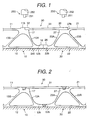
- Fig. 1 is an enlarged view showing an essential -portion of a side structure body of a railway vehicle of Fig. 3.
- Fig. 3 is a longitudinal cross-sectional view showing a side structure body of a structure body of Fig. 4.
- a car body 200 of a railway vehicle is comprised of a side structure body 201 for constituting a side face, a roof structure body 202 for constituting a roof, a stand frame 203 for constituting a floor, and a side structure body 204 for constituting an longitudinal direction end portion.
- Each of the side structure body 201, the roof structure body 202, and the stand frame 203 is constituted respectively by joining plural extruded frame members.
- a longitudinal direction of the extruded frame member is formed toward a longitudinal direction of the car body.
- the extruded frame member is a hollow frame member made of an aluminum alloy.
- a constitution and a joining method of a hollow extruded frame members 10 and 20 for constituting the side structure body 201 will be explained.
- Other portions and other structure bodies are similar to the above.
- the hollow frame members 10 and 20 are comprised of two sheet face plates 11, 12 and 21, 22 and plural ribs 13 and 23 arranged in a truss shape structure.
- the two sheet face plates 11 and 12 are substantially in parallel.
- the two sheetface plates 21 and 22 are substantially in parallel.
- a pitch of the truss structure according to the ribs 13 and 23 is the same.
- the truss structure is constituted by the ribs 13 and 23 and a center line of a plate thickness of the respective face plates 11, 12 and 21, 22.
- An apex is formed at a side of the face plates 11, 12 and 21, 22.
- rails 19 and 29 for installing machines and apparatuses are provided integrally.
- the rails 19 and 29 are comprised of L shape two members.
- the rails 19 and 29 become seats for installing the machines and apparatuses such as interior mounting plates and chairs and the like.
- End portions of the face plates 12 and 22 which are positioned at an outer face side of the car body project to a side of the adjacent hollow frame members 20 and 10 from the end portions of the face plates 11 and 21 in the inner side of the car of the railway vehicle. These projected face plates are indicated by 12b and 22b.
- a plate thickness of each of the face plates 12b and 22b is thicker than another portion of the face plates 12 and 22.
- the hollow frame members 10 and 20 are mounted on a bed 240 by laying the face plates 12 and 22 at the lower portion.
- the side of the face plates 11 and 21 are formed to the upper portion.
- a rotary tool 250 By inserting a rotary tool 250 to the joining portion from the upper portion the friction stir joining is carried out.
- the friction stir joining is carried out from the inner side of the railway vehicle.
- raised portions 16 and 26 which project in the inner side of the car (namely, the face plates 11 and 21 side) are provided. A width and a height of each of the raised portions 16 and 26 are substantially the same.
- connection member 30 The end portion of the face plate 11 in the inner side of the car and the end portion of the face plate 21 are joined through a connection member 30.
- the end portion of the connection member 30 is mounted or overlapped with the seats 17 and 27 which are provided on the apex of the truss structure.
- the seat 17 is formed at the end portion of the hollow frame member 10 from a normal line which passes through an intersecting point between the rib 13A and the rib 13B.
- a face reaching from the seat 17 to the outer face (the upper face) of the face plate 11 is formed on the above stated normal line.
- a raised portion 11b which projects to the outer face (the upper face) side is arranged.
- connection member 30 has a raised portion 32 which projects to the outer face (the upper face).
- a width and a height of the raised portions 11b and 32 are the same to those of the raised portions 16 and 26.
- the width of the seat 17 is the same as the width of the raised portion 32.
- the seat 27 is arranged at an intersecting point between the ribs 23A and the rib 23B as a center. At a center of the width of the seat 27 the above stated intersecting point is arranged. Namely, the apex of the truss structure of the end portion is arranged at a central portion of the width of the seat 27.
- the face reaching from the seat 27 to the face plate 22 is inclined as a groove for an arc welding to the connection member 30.
- a raised portion 35 is arranged at the end portion of the connection member 30 which mounts on the seat 27.
- a height of the raised portion 35 is similar to that of the raised portions 16, 26, 11b and 32.
- a width of the raised portion is similar to a combined width of the raised portions 16 and 26.
- connection member 30 is arranged to aim to continue the surfaces of the plate plates 11 and 21.
- the central portion, except for the both end portions, of the connection member 30 is a plate 31 and a plate thickness of the plate is substantially same to the plate thickness of the face plates 11 and 21.
- An upper face of the raised portion 35 has a V-shape groove 36.
- the groove 36 is arranged at a center of the width of the raised portion 35.
- a width of the raised portion 35 is larger than a diameter of a large diameter portion 252 of the rotary tool 250.
- the groove 36 becomes a subject matter for position detecting to lead the rotary tool 250.
- the groove 36 is detected by a laser sensor and the axial center of the rotary tool 250 is coincided with the groove 36.
- connection member 30 is smaller than the space between face plates 11 and 21 of the two hollow frame members 10 and 20.
- the connection member 30 is made of the extruded frame member having the same material of the hollow frame members 10 and 20.
- a length of the connection member 30 is the same as the length of the hollow frame members 10 and 20.
- a distance P from the end portion of the face plate 11 to the end portion of the face plate 21 is the same pitch P of the truss structure of the other positions.
- a distance from the apex of the truss structure of the end portion of the hollow frame member 10 and the apex of the truss structure of the end portion of the hollow frame member 20 is the same pitch P of the truss structure of the other positions.
- the truss structure of the hollow frame member is an isosceles triangle.
- the truss structure of the end portion of the hollow frame members 10 and 20 is not an isosceles triangle.
- the rib 13A is connected to a midway of the face plate 12 and the rib 23A is connected to a midway of the face plate 22. Between a connection portion between the rib 13A and the face plate 12 and a connection portion between the rib 23A and the face plate 22, a space for inserting the friction stir joining apparatus is formed.
- the manufacturing method of this structure body will be explained.
- the hollow frame members 10 and 20 are mounted on the bed 240.
- the face plates 12b and 22b are abutted.
- these frame members 10 and 20 are fixed on the bed 240.
- An upper face of the bed 240 on which the abutted portion of the face plates 12b and 22b are mounted is flat.
- Three portions, which are a point in the vicinity of the abutted portion of the face plates 12b and 22b, an intersecting point in the vicinity of the ribs 13A and 23A and the face plates 12b and 22b, and an intersecting point in the vicinity of the ribs 13B and 23B and the face plates 12 and 22 are mounted on the bed 240 having the same height.
- the rotary tool 250 of the friction stir joining apparatus is inserted from the upper portion to the abutted portion of the raised portions 16 and 26, is moved along to a joining line and then the friction stir joining is carried out.
- the axial center of the rotary tool 250 is a perpendicular direction (the direction along to the normal line of the joining portion). However, against an advancing direction of the rotary tool 250 the axial center is inclined as already known.
- the rotary tool 250 comprises the large diameter portion 252 and the small diameter portion 251 at a tip end of the large diameter portion 252.
- the tip end (the lower end) of the small diameter portion 251 of the rotary tool 250 is positioned in the vicinity of the lower face from the direction of the upper face of the face plates 12b and 22b.
- the lower end of the large diameter portion 252 of the rotary tool 250 is positioned between the apex of the raised portions 16 and 26 and between the face plates 12b and 22b of the inner side of the car (the face side of the plates 11 and 21).
- a diameter of the large diameter portion 252 of the rotary tool 250 is smaller than a width which is comprised of the two raised portions 16 and 26.
- the small diameter portion 251 of the rotary tool 250 forms a screw member.
- the raised portion 16 and 26 are detected by the laser sensor. According to this, a height position of the raised portions 16 and 26 is requested and an insertion amount of the rotary tool 250 is determined. Further, a gap of the abutted portion of the two raised portions 16 and 26 is requested and to this position the axial center of the rotary tool 250 is coincided with.
- the gap of the abutted portions of the face plate 12b and 22b is buried and joined.
- the original material of the metal for burying the gap is the raised portions 16 and 26.
- the outer face side (the outer side of the car) of the face plates 12b and 22b is joined flatly. To the outer face side of the face plates 12b and 22b, no recessed portion of the joining line exists.
- the upper face of the raised portions 16 and 26 becomes a convex form according to the large diameter portion 252 of the rotary tool 250. At the both ends of the recessed portion, the raised portions 16 and 26 are left.
- connection member 30 is mounted on the seats 17 and 27 of the face plates 11 and 21.
- One end (an end portion of the raised portion 32) of the connection member 30 is abutted against an end portion of the plate 11 (a boundary between the raised portion 11b and the seat 17).
- connection member 30 is fixed temporarily to the face plates 11 and 21 according to the arc welding manner. This temporary welding is carried out intermittently.
- connection member 30 is carried out.
- the rotary tool 250 is moved along to the joining line and the friction stir joining is carried out.
- a width of the raised portion 35 is larger than the diameter of the large diameter portion 2.52 of the rotary tool 250.
- the groove 36 is provided.
- the rotation axial center of the rotary tool 250 is coincided with the groove 36.
- a tip end of the small diameter portion 251 of the rotary tool 250 is inserted deeply into the seats 17 and 27. With this construction, the overlapping joining is carried out.
- the lower end of the large diameter portion 252 of the rotary tool 250 is positioned between the upper face of the connection member 30 being the non-raised portion and the apex of the raised portion 35.
- the upper face of the raised portion 35 becomes a recess according to the large diameter portion 252 of the rotary tool 250. At the both ends of the recessed portion the raised portion 35 is left.
- the above stated sensor of the friction stir joining apparatus detects the groove 36 and along the groove 36 the rotary tool 250 is moved.
- Fig. 2 is schematic view showing a condition of the joining portion of the structure body after the joining.
- a hatching portion shows the joining portion.
- the axial center of the rotary tool 250 is positioned at the apex point of the truss structure of the two ribs 13A and 13B (23A and 23B) or through the perpendicular line which passes through a vicinity thereof. Against the eccentric matter, it corresponds to an increase of the plate thickness of the ribs 13A and 13B (23A and 23B), a shape of the arc for connecting the rib and the face plate, a thickness of the connection member 30, and the thickness of the seats 17 and 27, etc..
- connection member 30 When two rotary tools are used, the joining of both ends of the connection member 30 can be carried out at the same time.
- one join is an overlapping coupling, and one is an abutted coupling, according to an improvement of the coupling efficiency and a reduction of a stress concentration in a bending portion, the strength can be improved.
- the arc welding can be lessened, a thermal distortion of the structure body can be lessened, an appearance of the structure body can be improved, further an installation of an interior mounting material can be carried out easily.
- the joining of the both faces of the hollow frame members is carried out from one side face. For this reason, it is unnecessary to reverse the structure body to which one face is joined. Accordingly, the structure body can be manufactured at a low cost and with a high accuracy.
- the raised portions 16, 26 and 35 are arranged in the inner side of the structure body and the inner side of the car but do not exist at a portion (the outer face side, the outer side of the car) in which a flat face is require.
- the bed 240 can be replaced by a backing member such as a roller etc..
- the strength of the joining portion of the overlapping portion (the joining portion of the seat 27 and the connection member 30) and the strength of the bending portion of the place plate 21 are inferior to the strength the abutted portion (the joining portion of the face plate 11 and the connection member 30).
- connection member 30 and the end portion of the face plate 21 are joined according to the arc welding manner.
- This arc welding can be carried out at a portion necessary to have more strength, for example only at a position near to a window corner.
- the member which is joined by the above stated manner can be used as an outer face (a face to be viewed by eye) of the structure member such as a building structure.
- the portion for mounting the connection member 30. can be set at the structure and the portion in which it can bear to the load during the friction stir joining.
- the structure and the portion can be set as shown in Fig. 9 of the above stated document of Japanese application patent laid-open publication No. Hei 9-309164 (EP 0797043 A2).
- FIG. 5A and Fig. 5B A further structure body achieved by carrying out friction stir joining is shown in Fig. 5A and Fig. 5B, and will now be explained.
- This is suited for a case in which by joining three and more than three hollow frame members a large structure body is manufactured.
- the side structure body 201 is constituted by the three frame members.
- the relationship between the hollow frame member 10 (for example, a first frame member) and the hollow frame member 20 (for example, a second frame member and a central frame member) at the left side and the connection member 30 is similar to the embodiment of the structure body shown in Fig. 1.
- a hollow frame member 40 for example, a third frame member
- connection member 30B To another end (the right end) of the central hollow frame member 20 (the second frame member) the left end of a hollow frame member 40 (for example, a third frame member) and the connection member 30B are joined.
- the left end of the hollow frame member 40 (the third frame member) and the connection member 30B are the same as the left end of the central hollow frame member 20 (the second frame member) and the connection member 30.
- the structure of the another end (the right end) of the central hollow frame member 20 (the second frame member) is the same the structure of the right end of the hollow frame member 10 (the first frame member).
- the structure of the left end of the hollow frame member 40 (the third frame member) which is joined to the right end of this hollow frame member 10 (the first frame member) is same to the right end of the central hollow frame member 20 (the second frame member).
- the structure and the direction of the connection member 30B are the same as those of the connection member 30.
- the left end of the central hollow frame member 20 (the second frame member) and the hollow frame member 10 (the first frame member) are shown in Fig. 5A.
- the right end of the central hollow frame member 20 (the second frame member) and the hollow frame member 40 (the third frame member) are shown in Fig. 5B.
- the left end of the central frame member 20 (the second frame member) shown in Fig. 5A extends to the right end of the central frame member 20 (the second frame member) shown in Fig. 5B, and an intermediate portion of the right end of the central frame member 20 (the second frame member) is omitted.
- the hollow frame member 40 (the third frame member) is comprised of two sheet face plates 41 and 42, plural ribs 43A and 43B arranged in a truss structure and a seat 47.
- the face plate 42 has a projected plate 42b and a raised portion 46 and the face plate 41 has a slope face 47b.
- a slope face 27b is provided, and to another end (the right end) of the face plate 21 a raised portion (corresponding to the raised portion 11b) is provided.
- connection members 30 since the directions of the raised portions 32 of the plural connection members 30 direct in the same direction, the erroneous arrangement of the connection members 30 can be lessened.
- the joining procedure is that the three hollow frame members 10, 20 and 40 are mounted on the bed 240 and restricted.
- the process is similar to that of a case of Fig. 1.
- the good joining from one side face of the hollow frame member can be carried out.
Landscapes
- Engineering & Computer Science (AREA)
- Mechanical Engineering (AREA)
- Pressure Welding/Diffusion-Bonding (AREA)
- Panels For Use In Building Construction (AREA)
Claims (4)
- Reibrührschweißverfahren, bei dem(i) zwei hohle Rahmenelemente (10, 20) vorgesehen werden, deren jedes eine erste (11, 12) und eine zweite (21, 22) Deckplatte aufweist, die in Dickenrichtung des hohlen Rahmenelements in Abstand voneinander angeordnet und über mehrere Rippen (13, 23) verbunden sind, wobei jede Deckplatte (11, 12, 21, 22) sich in seitlicher Richtung quer zu der Dickenrichtung erstreckt und an jeder Seitenkante einen Endabschnitt aufweist, und wobei an jedem hohlen Rahmenelement der Endabschnitt (12b, 22b) der zweiten Deckplatte (12, 22) über den Endabschnitt der ersten Deckplatte (11, 21) hinausragt,(ii) die Endabschnitte (12b, 22b) der jeweils zweiten Deckplatten (12, 22) durch Reibrührschweißen mittels eines an der innenseite der Endabschnitte (12b, 22b) angesetzten rotierenden Reibrührschweißwerkzeugs verbunden werden,(iii) ein Verbindungselement (30) mit entgegengesetzten ersten und zweiten Enden vorgesehen wird und diese Enden jeweils an den Endabschnitten der ersten Deckplatten (11, 21) des ersten und des zweiten hohlen Rahmenelements angeordnet werden, wobei die Enden des Verbindungselements (30) jeweilige Auflageabschnitte (17, 27) der hohlen Rahmenelemente überlappen,(iv) das erste Ende des Verbindungselements (30) mit dem Endabschnitt der ersten Deckplatte (11) des ersten hohlen Rahmenelements (10) durch Reibrührschweißen mittels eines rotierenden Reibrührschweißwerkzeugs (250) verbunden wird, das an der Außenseite des ersten hohlen Rahmenelements (10) und an in der Dickenrichtung verlaufenden aneinanderstoßenden Flächen des Verbindungselements (30) und des ersten hohlen Rahmenelements (10) angesetzt wird, und(v) das zweite Ende des Verbindungselements (30) und der Endabschnitt der ersten Deckplatte (21) des zweiten hohlen Rahmenelements (20) durch Reibrührschweißen mittels eines an der Außenseite des zweiten hohlen Rahmenelements (20) angesetzten Reibrührschweißwerkzeugs (250) verbunden werden,dadurch gekennzeichnet, dass der Schritt (v) durch Ansetzen des rotierenden Reibrührschweißwerkzeugs an einer Stelle in Abstand vom äußersten Ende des Verbindungselements (30) durchgeführt wird, wobei sich die Reibrührschweißzone über die gesamte Dicke des Verbindungselements (30) und in den überlappten Auflagebereich (27) hinein erstreckt.
- Reibrührschweißverfahren nach Anspruch 1, wobei das zweite Ende des Verbindungselements (30) einen erhabenen Abschnitt (35) aufweist, der an der Stelle der Reibrührverschweißung in Dickenrichtung an seiner Außenseite herausragt.
- Reibrührschweißverfahren nach Anspruch 2, wobei in der Mitte des erhabenen Abschnitts (35) eine Nut (36) vorgesehen wird, die zur Platzierung des Reibrührschweißwerkzeugs benutzt wird.
- Strukturkörper mit zwei miteinander verbundenen hohlen Rahmenelementen (10, 20), wobei
jedes hohle Rahmenelement (10, 20) eine erste (11, 12) und eine zweite (21, 22) Deckplatte aufweist, die in Dickenrichtung des hohlen Rahmenelements in Abstand voneinander angeordnet und über mehrere Rippen (13, 23) verbunden sind, wobei jede Deckplatte (11, 12, 21, 22) sich in seitlicher Richtung quer zu der Dickenrichtung erstreckt und an jeder Seitenkante einen Endabschnitt aufweist, und wobei an jedem hohlen Rahmenelement der Endabschnitt (12b, 22b) der zweiten Deckplatte (12, 22) über den Endabschnitt der ersten Deckplatte (11, 21) hinausragt,
die Endabschnitte (12b, 22b) der jeweils zweiten Deckplatten (12, 22) durch Reibrührschweißen miteinander verbunden sind, das mittels eines an der Innenseite der Endabschnitte (12b, 22b) angesetzten Werkzeugs durchgeführt wurde,
ein Verbindungselement (30) mit entgegengesetzten ersten und zweiten Enden vorgesehen ist, die mit den jeweiligen Endabschnitten der ersten Deckplatten (11, 21) des ersten und des zweiten Rahmenelements verbunden sind, wobei die Enden des Verbindungselements (30) jeweilige Auflageabschnitte (17, 27) der hohlen Rahmenelemente überlappen,
das erste Ende des Verbindungselements (30) und der Endabschnitt der ersten Deckplatte (11) des ersten hohlen Rahmenelements (10) durch Reibrührschweißen verbunden sind, das mittels eines an der Außenseite des ersten hohlen Rahmenelements (10) und an in der Dickenrichtung verlaufenden aneinanderstoßenden Flächen des Verbindungselements (30) und des ersten hohlen Rahmenelements (10) angesetzten rotierenden Reibrührschweißwerkzeugs (250) durchgeführt ist, und
das zweite Ende des Verbindungselements (30) und der Endabschnitt der ersten Deckplatte (21) des zweiten hohlen Rahmenelements (20) durch Reibrührschweißen verbunden sind, das mittels eines an der Außenseite des zweiten hohlen Rahmenelements (20) angesetzten Reibrührschweißwerkzeugs (250) durchgeführt wurde,
dadurch gekennzeichnet, dass die Stelle der Reibrührverschweißung des zweiten Endes des Verbindungselements (30) und des Endabschnitts der ersten Deckplatte (21) des zweiten hohlen Rahmenelements (20) in Abstand vom äußersten Ende des Verbindungselements (30) liegt, wobei sich die Reibrührschweißzone über die gesamte Dicke des Verbindungselements (30) und in den überlappten Auflagebereich (27) hinein erstreckt.
Applications Claiming Priority (2)
| Application Number | Priority Date | Filing Date | Title |
|---|---|---|---|
| JP2000013670 | 2000-01-24 | ||
| JP2000013670A JP3538357B2 (ja) | 2000-01-24 | 2000-01-24 | 摩擦攪拌接合方法 |
Publications (3)
| Publication Number | Publication Date |
|---|---|
| EP1123770A2 EP1123770A2 (de) | 2001-08-16 |
| EP1123770A3 EP1123770A3 (de) | 2003-12-17 |
| EP1123770B1 true EP1123770B1 (de) | 2006-05-03 |
Family
ID=18541227
Family Applications (1)
| Application Number | Title | Priority Date | Filing Date |
|---|---|---|---|
| EP00306787A Expired - Lifetime EP1123770B1 (de) | 2000-01-24 | 2000-08-09 | Drehendes Reibungschweissverfahren und Struktureller Körper. |
Country Status (7)
| Country | Link |
|---|---|
| US (3) | US6276591B1 (de) |
| EP (1) | EP1123770B1 (de) |
| JP (1) | JP3538357B2 (de) |
| KR (3) | KR100459092B1 (de) |
| AU (1) | AU742987B2 (de) |
| DE (1) | DE60027687T2 (de) |
| TW (1) | TW460347B (de) |
Families Citing this family (29)
| Publication number | Priority date | Publication date | Assignee | Title |
|---|---|---|---|---|
| US6581819B1 (en) * | 1996-03-19 | 2003-06-24 | Hitachi, Ltd. | Panel structure, a friction stir welding method, and a panel |
| JP3070735B2 (ja) * | 1997-07-23 | 2000-07-31 | 株式会社日立製作所 | 摩擦攪拌接合方法 |
| JP3563003B2 (ja) * | 1999-09-30 | 2004-09-08 | 株式会社日立製作所 | 構造体の摩擦攪拌接合方法 |
| JP3459210B2 (ja) * | 1999-11-24 | 2003-10-20 | 株式会社日立製作所 | 摩擦攪拌接合方法 |
| JP3288669B2 (ja) | 2000-01-25 | 2002-06-04 | 川崎重工業株式会社 | 摩擦撹拌接合ホロー材の継手構造 |
| JP3552978B2 (ja) * | 2000-01-27 | 2004-08-11 | 株式会社日立製作所 | 中空形材 |
| JP3589930B2 (ja) * | 2000-02-25 | 2004-11-17 | 株式会社日立製作所 | 摩擦攪拌接合方法 |
| AU2005200430B2 (en) * | 2001-01-17 | 2007-01-04 | Hitachi, Ltd. | Friction stir welding method, and method for manufacturing car body |
| JP3761786B2 (ja) * | 2001-01-17 | 2006-03-29 | 株式会社日立製作所 | 摩擦攪拌接合方法および装置 |
| JP3751215B2 (ja) * | 2001-04-16 | 2006-03-01 | 株式会社日立製作所 | 摩擦攪拌接合方法 |
| US20050070374A1 (en) * | 2003-09-29 | 2005-03-31 | Technology Licensing, Llc | Enhanced golf club performance via friction stir processing |
| US8875976B2 (en) | 2005-09-26 | 2014-11-04 | Aeroprobe Corporation | System for continuous feeding of filler material for friction stir welding, processing and fabrication |
| US8632850B2 (en) | 2005-09-26 | 2014-01-21 | Schultz-Creehan Holdings, Inc. | Friction fabrication tools |
| US9511445B2 (en) | 2014-12-17 | 2016-12-06 | Aeroprobe Corporation | Solid state joining using additive friction stir processing |
| US9511446B2 (en) | 2014-12-17 | 2016-12-06 | Aeroprobe Corporation | In-situ interlocking of metals using additive friction stir processing |
| US20080041921A1 (en) | 2005-09-26 | 2008-02-21 | Kevin Creehan | Friction stir fabrication |
| US9266191B2 (en) | 2013-12-18 | 2016-02-23 | Aeroprobe Corporation | Fabrication of monolithic stiffening ribs on metallic sheets |
| JP4266024B2 (ja) * | 2006-03-28 | 2009-05-20 | 株式会社日立製作所 | 軌条車両、その製作方法、及びそれに用いる中空形材 |
| FR2907040B1 (fr) | 2006-10-13 | 2009-06-26 | Alstom Transport Sa | Procede d'assemblage d'une structure comportant un exterieur et un interieur constituee d'une pluralite d'elements a double peau,telle qu'une caisse de vehicule ferroviaire,et structure obtenue. |
| WO2013002869A2 (en) | 2011-04-07 | 2013-01-03 | Schultz-Creehan Holdings, Inc. | System for continuous feeding of filler material for friction stir fabrication and self-reacting friction stir welding tool |
| US8590767B2 (en) | 2011-06-21 | 2013-11-26 | Research Institute Of Industrial Science & Technology | Method for welding hollow structure |
| KR101595923B1 (ko) * | 2012-02-23 | 2016-02-26 | 카와사키 주코교 카부시키 카이샤 | 저지붕 구조체를 구비한 철도 차량 |
| JP6274079B2 (ja) * | 2014-11-04 | 2018-02-07 | 日本軽金属株式会社 | ペリクル用支持枠および製造方法 |
| CN105081596A (zh) * | 2015-09-06 | 2015-11-25 | 唐山轨道客车有限责任公司 | 用于搅拌摩擦焊的焊接接头 |
| WO2019089764A1 (en) | 2017-10-31 | 2019-05-09 | Aeroprobe Corporation | Solid-state additive manufacturing system and material compositions and structures |
| JP2019217546A (ja) * | 2018-06-22 | 2019-12-26 | 株式会社神戸製鋼所 | めっき鋼板の接合方法及び接合構造体 |
| CN108723578B (zh) * | 2018-07-18 | 2021-01-22 | 中车长春轨道客车股份有限公司 | 中空铝型材拼合圆弧板的搅拌摩擦焊接方法 |
| CN108857045B (zh) * | 2018-07-25 | 2020-11-13 | 辽宁忠旺铝合金精深加工有限公司 | 侧墙搅拌摩擦焊控制变形工艺 |
| CN111014938B (zh) * | 2019-12-18 | 2022-03-29 | 南京雷尔伟新技术股份有限公司 | 一种车顶或底架搅拌摩擦焊焊接实施工艺 |
Family Cites Families (23)
| Publication number | Priority date | Publication date | Assignee | Title |
|---|---|---|---|---|
| US3221467A (en) * | 1963-02-01 | 1965-12-07 | American Metalcore Systems Inc | Structural member |
| US3790120A (en) * | 1971-12-13 | 1974-02-05 | Flexicore Co | Composite slab casting form |
| US3883972A (en) * | 1972-10-03 | 1975-05-20 | Miller Herman Inc | Universal mounting for various signage |
| JPH0642215B2 (ja) * | 1988-01-28 | 1994-06-01 | インターナシヨナル・ビジネス・マシーンズ・コーポレーシヨン | 分散式監視サブシステム |
| US5199632A (en) * | 1989-06-30 | 1993-04-06 | Hitachi. Ltd. | Railway car body structures and methods of making them |
| GB9125978D0 (en) * | 1991-12-06 | 1992-02-05 | Welding Inst | Hot shear butt welding |
| WO1995026663A1 (de) * | 1994-03-30 | 1995-10-12 | Symalit Ag | Zweischalige tragvorrichtung für sitzlehnen-baugruppe |
| US5524407A (en) * | 1994-09-12 | 1996-06-11 | Selfix, Inc. | Modular shutter and retention assembly |
| JP3807766B2 (ja) | 1996-02-20 | 2006-08-09 | 株式会社日立製作所 | 鉄道車両構体の製作方法 |
| US6581819B1 (en) * | 1996-03-19 | 2003-06-24 | Hitachi, Ltd. | Panel structure, a friction stir welding method, and a panel |
| JPH1035487A (ja) * | 1996-07-19 | 1998-02-10 | Hitachi Ltd | 車両構体およびその製作方法 |
| JP3589863B2 (ja) * | 1997-07-23 | 2004-11-17 | 株式会社日立製作所 | 構造体および摩擦攪拌接合方法 |
| JP3070735B2 (ja) * | 1997-07-23 | 2000-07-31 | 株式会社日立製作所 | 摩擦攪拌接合方法 |
| JPH1158036A (ja) * | 1997-08-07 | 1999-03-02 | Hitachi Ltd | 摩擦溶接方法および溶接継手構造 |
| JPH1158039A (ja) * | 1997-08-18 | 1999-03-02 | Showa Alum Corp | 摩擦撹拌接合による重ね継手及びその形成方法 |
| US6099194A (en) * | 1997-08-20 | 2000-08-08 | Dana Corporation | Splice joint for connecting adjacent side rail sections in a vehicle body and frame assembly |
| JP3262161B2 (ja) * | 1998-02-12 | 2002-03-04 | 日本軽金属株式会社 | アルミニウム系押出形材の摩擦攪拌接合方法および摩擦攪拌接合用アルミニウム系押出形材 |
| JP3297847B2 (ja) * | 1998-03-17 | 2002-07-02 | 住友軽金属工業株式会社 | 摩擦接合用部材とその接合方法及び接合パネル |
| JP3307330B2 (ja) * | 1998-06-01 | 2002-07-24 | 日本軽金属株式会社 | 厚肉の被接合材の摩擦攪拌接合方法及び接合構造 |
| JP2000153374A (ja) * | 1998-11-18 | 2000-06-06 | Hitachi Ltd | 摩擦攪拌接合装置及び摩擦攪拌接合ツール並びに摩擦攪拌接合構造物 |
| US6152511A (en) * | 1999-02-22 | 2000-11-28 | Gustafson; Leonard L. | Convertible trailer system |
| JP2000343245A (ja) * | 1999-05-31 | 2000-12-12 | Hitachi Ltd | 構造体の製作方法 |
| JP3288669B2 (ja) | 2000-01-25 | 2002-06-04 | 川崎重工業株式会社 | 摩擦撹拌接合ホロー材の継手構造 |
-
2000
- 2000-01-24 JP JP2000013670A patent/JP3538357B2/ja not_active Expired - Fee Related
- 2000-08-09 DE DE60027687T patent/DE60027687T2/de not_active Expired - Lifetime
- 2000-08-09 EP EP00306787A patent/EP1123770B1/de not_active Expired - Lifetime
- 2000-08-09 TW TW089116040A patent/TW460347B/zh not_active IP Right Cessation
- 2000-08-14 US US09/637,020 patent/US6276591B1/en not_active Expired - Fee Related
- 2000-08-24 AU AU53631/00A patent/AU742987B2/en not_active Ceased
- 2000-08-30 KR KR10-2000-0050619A patent/KR100459092B1/ko not_active Expired - Fee Related
-
2001
- 2001-02-20 US US09/785,482 patent/US6461072B2/en not_active Expired - Fee Related
- 2001-02-20 US US09/785,481 patent/US6568872B2/en not_active Expired - Fee Related
-
2004
- 2004-04-19 KR KR1020040026667A patent/KR20040039248A/ko not_active Ceased
- 2004-04-19 KR KR1020040026666A patent/KR20040039247A/ko not_active Ceased
Also Published As
| Publication number | Publication date |
|---|---|
| DE60027687T2 (de) | 2007-01-25 |
| US6568872B2 (en) | 2003-05-27 |
| DE60027687D1 (de) | 2006-06-08 |
| AU742987B2 (en) | 2002-01-17 |
| AU5363100A (en) | 2001-07-26 |
| KR100459092B1 (ko) | 2004-12-03 |
| KR20010076184A (ko) | 2001-08-11 |
| US6461072B2 (en) | 2002-10-08 |
| JP3538357B2 (ja) | 2004-06-14 |
| US20010009334A1 (en) | 2001-07-26 |
| JP2001205456A (ja) | 2001-07-31 |
| EP1123770A2 (de) | 2001-08-16 |
| US6276591B1 (en) | 2001-08-21 |
| EP1123770A3 (de) | 2003-12-17 |
| KR20040039248A (ko) | 2004-05-10 |
| US20010009723A1 (en) | 2001-07-26 |
| KR20040039247A (ko) | 2004-05-10 |
| TW460347B (en) | 2001-10-21 |
Similar Documents
| Publication | Publication Date | Title |
|---|---|---|
| EP1123770B1 (de) | Drehendes Reibungschweissverfahren und Struktureller Körper. | |
| EP1129810B1 (de) | Reibrührschweissverfahren und Profilteil zur Verwendung in einem Reibrührschweissverfahren | |
| EP1103334B1 (de) | Drehendes Reibungschweissverfahren | |
| EP1057574B1 (de) | Struktureller Körper und Verfahren zu seiner Herstellung | |
| EP1055478B1 (de) | Bauteil und Verfahren zu seiner Herstellung | |
| JP3459211B2 (ja) | 摩擦攪拌接合用形材 | |
| JP3459218B2 (ja) | 摩擦攪拌接合方法 | |
| AU2002301555B2 (en) | A frame member | |
| JP3608997B2 (ja) | 摩擦攪拌接合用中空形材及び接続材 | |
| JP2001071897A (ja) | 摩擦攪拌接合用中空形材 | |
| JP2001205455A (ja) | 摩擦攪拌接合方法 | |
| JP2001073499A (ja) | 構造体およびその製作方法 | |
| JP2002059278A (ja) | 摩擦攪拌接合方法 |
Legal Events
| Date | Code | Title | Description |
|---|---|---|---|
| PUAI | Public reference made under article 153(3) epc to a published international application that has entered the european phase |
Free format text: ORIGINAL CODE: 0009012 |
|
| 17P | Request for examination filed |
Effective date: 20000828 |
|
| AK | Designated contracting states |
Kind code of ref document: A2 Designated state(s): AT BE CH CY DE DK ES FI FR GB GR IE IT LI LU MC NL PT SE |
|
| AX | Request for extension of the european patent |
Free format text: AL;LT;LV;MK;RO;SI |
|
| PUAL | Search report despatched |
Free format text: ORIGINAL CODE: 0009013 |
|
| AK | Designated contracting states |
Kind code of ref document: A3 Designated state(s): AT BE CH CY DE DK ES FI FR GB GR IE IT LI LU MC NL PT SE |
|
| AX | Request for extension of the european patent |
Extension state: AL LT LV MK RO SI |
|
| RTI1 | Title (correction) |
Free format text: FRICTION STIR JOINING METHOD |
|
| AKX | Designation fees paid |
Designated state(s): DE FR GB IT SE |
|
| 17Q | First examination report despatched |
Effective date: 20050525 |
|
| GRAP | Despatch of communication of intention to grant a patent |
Free format text: ORIGINAL CODE: EPIDOSNIGR1 |
|
| RTI1 | Title (correction) |
Free format text: FRICTION STIR JOINING METHOD AND STRUCTURAL BODY |
|
| GRAS | Grant fee paid |
Free format text: ORIGINAL CODE: EPIDOSNIGR3 |
|
| GRAA | (expected) grant |
Free format text: ORIGINAL CODE: 0009210 |
|
| AK | Designated contracting states |
Kind code of ref document: B1 Designated state(s): DE FR GB IT SE |
|
| REG | Reference to a national code |
Ref country code: GB Ref legal event code: FG4D |
|
| REF | Corresponds to: |
Ref document number: 60027687 Country of ref document: DE Date of ref document: 20060608 Kind code of ref document: P |
|
| REG | Reference to a national code |
Ref country code: SE Ref legal event code: TRGR |
|
| ET | Fr: translation filed | ||
| PLBE | No opposition filed within time limit |
Free format text: ORIGINAL CODE: 0009261 |
|
| STAA | Information on the status of an ep patent application or granted ep patent |
Free format text: STATUS: NO OPPOSITION FILED WITHIN TIME LIMIT |
|
| 26N | No opposition filed |
Effective date: 20070206 |
|
| PGFP | Annual fee paid to national office [announced via postgrant information from national office to epo] |
Ref country code: SE Payment date: 20090626 Year of fee payment: 10 |
|
| PGFP | Annual fee paid to national office [announced via postgrant information from national office to epo] |
Ref country code: FR Payment date: 20090723 Year of fee payment: 10 |
|
| PGFP | Annual fee paid to national office [announced via postgrant information from national office to epo] |
Ref country code: GB Payment date: 20090728 Year of fee payment: 10 Ref country code: DE Payment date: 20090824 Year of fee payment: 10 |
|
| PGFP | Annual fee paid to national office [announced via postgrant information from national office to epo] |
Ref country code: IT Payment date: 20090721 Year of fee payment: 10 |
|
| EUG | Se: european patent has lapsed | ||
| GBPC | Gb: european patent ceased through non-payment of renewal fee |
Effective date: 20100809 |
|
| REG | Reference to a national code |
Ref country code: FR Ref legal event code: ST Effective date: 20110502 |
|
| PG25 | Lapsed in a contracting state [announced via postgrant information from national office to epo] |
Ref country code: IT Free format text: LAPSE BECAUSE OF NON-PAYMENT OF DUE FEES Effective date: 20100809 |
|
| REG | Reference to a national code |
Ref country code: DE Ref legal event code: R119 Ref document number: 60027687 Country of ref document: DE Effective date: 20110301 |
|
| PG25 | Lapsed in a contracting state [announced via postgrant information from national office to epo] |
Ref country code: FR Free format text: LAPSE BECAUSE OF NON-PAYMENT OF DUE FEES Effective date: 20100831 Ref country code: DE Free format text: LAPSE BECAUSE OF NON-PAYMENT OF DUE FEES Effective date: 20110301 |
|
| PG25 | Lapsed in a contracting state [announced via postgrant information from national office to epo] |
Ref country code: GB Free format text: LAPSE BECAUSE OF NON-PAYMENT OF DUE FEES Effective date: 20100809 |
|
| PG25 | Lapsed in a contracting state [announced via postgrant information from national office to epo] |
Ref country code: SE Free format text: LAPSE BECAUSE OF NON-PAYMENT OF DUE FEES Effective date: 20100810 |