EP1123777B1 - Vorrichtung zum Entschärfen von Munition durch Wasserstrahlschneiden mit niedrigem Druck - Google Patents
Vorrichtung zum Entschärfen von Munition durch Wasserstrahlschneiden mit niedrigem Druck Download PDFInfo
- Publication number
- EP1123777B1 EP1123777B1 EP01400324A EP01400324A EP1123777B1 EP 1123777 B1 EP1123777 B1 EP 1123777B1 EP 01400324 A EP01400324 A EP 01400324A EP 01400324 A EP01400324 A EP 01400324A EP 1123777 B1 EP1123777 B1 EP 1123777B1
- Authority
- EP
- European Patent Office
- Prior art keywords
- water
- cutting
- abrasive
- abrasive jet
- circular cutting
- Prior art date
- Legal status (The legal status is an assumption and is not a legal conclusion. Google has not performed a legal analysis and makes no representation as to the accuracy of the status listed.)
- Expired - Lifetime
Links
Images


Classifications
-
- B—PERFORMING OPERATIONS; TRANSPORTING
- B24—GRINDING; POLISHING
- B24C—ABRASIVE OR RELATED BLASTING WITH PARTICULATE MATERIAL
- B24C1/00—Methods for use of abrasive blasting for producing particular effects; Use of auxiliary equipment in connection with such methods
- B24C1/04—Methods for use of abrasive blasting for producing particular effects; Use of auxiliary equipment in connection with such methods for treating only selected parts of a surface, e.g. for carving stone or glass
- B24C1/045—Methods for use of abrasive blasting for producing particular effects; Use of auxiliary equipment in connection with such methods for treating only selected parts of a surface, e.g. for carving stone or glass for cutting
-
- B—PERFORMING OPERATIONS; TRANSPORTING
- B24—GRINDING; POLISHING
- B24C—ABRASIVE OR RELATED BLASTING WITH PARTICULATE MATERIAL
- B24C3/00—Abrasive blasting machines or devices; Plants
- B24C3/02—Abrasive blasting machines or devices; Plants characterised by the arrangement of the component assemblies with respect to each other
-
- B—PERFORMING OPERATIONS; TRANSPORTING
- B24—GRINDING; POLISHING
- B24C—ABRASIVE OR RELATED BLASTING WITH PARTICULATE MATERIAL
- B24C3/00—Abrasive blasting machines or devices; Plants
- B24C3/02—Abrasive blasting machines or devices; Plants characterised by the arrangement of the component assemblies with respect to each other
- B24C3/04—Abrasive blasting machines or devices; Plants characterised by the arrangement of the component assemblies with respect to each other stationary
Definitions
- the technical sector of the present invention is that of circular cutting devices by abrasive water jet used for the neutralization of explosive devices, including improvised explosive devices or trapped packages placed inside a strong enclosure.
- 5,759,086 which describes a device for cutting parts by abrasive blasting.
- This device consists in particular of a cutting head, comprising at least two guns, each emitting a jet. Mon guns are movable with respect to each other, so that the axes of the guns form an angle such that the jets converge at the same point of cut.
- the cutting head is intended to be mounted on a moving rail.
- This device has the disadvantage of being able to allow cutting only rectilinearly.
- doubling the impact of the jet on the same point can cause significant vibration and heating of the workpiece, phenomena to avoid when neutralizing explosive devices.
- the object of the present invention is to overcome the drawbacks mentioned above, by proposing a circular cutting device, intended to overcome the phenomenon of residual attachment, to ensure a fast cutting time.
- the present invention also aims to provide a circular cutting device, implementing a lower abrasive jet pressure vis-à-vis existing devices to overcome the vibration and heating phenomena encountered during cutting.
- Another aim is, finally, to set up a circular cutting device, overcoming the risk of obstruction of the pipes and wear of the head.
- the invention relates to an abrasive water jet circular cutting device comprising a cutting head equipped with at least two guns having parallel axes. These guns have the particularity of being mounted, each of them, at different distances from the axis of the cutting head, at a barrel chamber, surmounted by a distribution chamber.
- the spacing distance in the implantation of the barrels relative to the cutting head axis has a value less than or equal to the thickness of the cutting line caused by the abrasive water jet.
- Each barrel has a nozzle mixing chamber and an abrasive inlet.
- the distribution chamber is connected to a water inlet under pressure. Preferably, this arrival will be set at a pressure of less than 200 bar.
- This device is characterized in that the dispensing chamber is surmounted by a needle valve actuated, preferably, by a pneumatic, hydraulic or electrical type of control. The entire device is driven by a rotational movement, preferably with the aid of a geared motor.
- This circular cutting device developed with several guns, placed at distances from the cutting head axis, has the advantage of reducing the cutting cycle time and performing a total cut, without residual attachment, with the maximum guarantee.
- the abrasive water jet circular cutting device has the advantage of being a device requiring a lower energy source than for other devices.
- the principle of performing abrasive mixing directly in the head also has the advantage of reducing the wear of the components, and increasing their longevity, and gives greater efficiency to drilling and cutting.
- Another advantage lies in the use of a low pressure, less than or equal to 200 bars. The use of such a pressure eliminates the vibrations induced on the explosive device and also reduces the total thrust force to less than 1 daN on the entire machine treated. The risks of movement and untimely explosion are thus minimized.
- the use of a low pressure also makes it possible to bring a lot of water and to avoid overheating due to cutting, as well as the phenomenon of sparkling.
- FIG. 1 is a presentation by the vertical axis of the circular cutting device by abrasive water jet.
- This device consists of a water distribution chamber (1) connected to a water inlet under pressure of less than 200 bar (2) and surmounted by a needle valve (3).
- This needle valve is actuated by pneumatic, hydraulic or electric control (4).
- the water distribution chamber (1) is secured to a barrel chamber (5).
- This chamber assembles the guns (6), each equipped with a mixing chamber with nozzle (9) and an abrasive inlet (7).
- the entire cutting device is rotated by a gear motor (8).
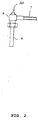
- FIG. 2 shows an overview of the system comprising the barrel (6), the mixing chamber with nozzle (9) and the abrasive inlet (7), as well as the water (10) allowing the mounting on the barrel chamber (5).
- the water supplied by the feed (2) is admitted into the distribution chamber (1) through an orifice released by the needle valve (3) actuated by the control system (4). This water reaches a dynamic pressure less than or equal to 200 bars.
- the flow of water is established in the mixing chambers (9) and by venturi effect causes the additive of the polymer or abrasive type coming from each mixing chamber by the arrivals (7).
- This additive is sucked and mixed with pressurized water from the distribution chamber (1).
- the water / additive pressure mixture exits through the guns (6).
- the circular cutting operation can begin. It is a question first to make a hole of drilling. Once this hole is made, the circular cut can begin, by the rotation of the cutting head, controlled by the gear motor (8). To reduce the angle of rotation, and therefore the cutting time, the head shown in Figure 1 was equipped with four barrels.
- this cutting head is the provision of these guns (6) on the guns chamber (5) to eliminate the phenomenon of residual attachment.
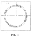
- the four guns were arranged in pairs at a distance different from the axis of the cutting head. This difference in distance has as a maximum value the thickness of the cut line caused by the jet of abrasive water.
- the abrasive water mixing jet does not pass back into an initial drilling hole and the prolongation of the rotation of the cutting head over an angle greater than 90 degrees ensures a complete cut with removal of any residual fastener.
Landscapes
- Engineering & Computer Science (AREA)
- Mechanical Engineering (AREA)
- Perforating, Stamping-Out Or Severing By Means Other Than Cutting (AREA)
- Electrical Discharge Machining, Electrochemical Machining, And Combined Machining (AREA)
- Earth Drilling (AREA)
- Nozzles (AREA)
Claims (8)
- Vorrichtung zum kreisförmigen Schneiden mittels abrasivem Wasserstrahl, mit einem Schneidekopf, der mit mindestens zwei Kanonen (6) ausgestattet ist, wobei diese Kanonen (6) in unterschiedlichen Abständen zur Achse des Schneidekopfs angebracht sind, dadurch gekennzeichnet, dass diese Kanonen parallele Achsen aufweisen und so angeordnet sind, dass der Abstandsunterschied in der Anbringung der Kanonen zur Achse des Schneidkopfs einen Wert hat, der kleiner als die oder gleich der Dicke der vom abrasiven Wasserstrahl (13) verursachten Schneidelinie ist.
- Vorrichtung zum kreisförmigen Schneiden mittels abrasivem Wasserstrahl nach Anspruch 1, dadurch gekennzeichnet, dass die Kanonen (6) jeweils eine Mischkammer mit Düse (9) und eine Abrasivstoffzufuhr (7) aufweisen.
- Vorrichtung zum kreisförmigen Schneiden mittels abrasivem Wasserstrahl nach Anspruch 2, dadurch gekennzeichnet, dass sie eine Kanonenträgerkammer (5) aufweist die von einer Verteilungskammer (1) überragt ist.
- Vorrichtung zum kreisförmigen Schneiden mittels abrasivem Wasserstrahl nach Anspruch 3, dadurch gekennzeichnet, dass die Verteilungskammer (1) mit einem Druckwasserzulauf (2) verbunden ist.
- Vorrichtung zum kreisförmigen Schneiden mittels abrasivem Wasserstrahl nach Anspruch 4, dadurch gekennzeichnet, dass der Wasserzulauf (2) auf einem Druck von weniger als 200 bar festgelegt ist.
- Vorrichtung zum kreisförmigen Schneiden mittels abrasivem Wasserstrahl nach Anspruch 4 oder 5, dadurch gekennzeichnet, dass die Verteilungskammer (1) von einem Nadelschieber (3) überragt ist.
- Vorrichtung zum kreisförmigen Schneiden mittels abrasivem Wasserstrahl nach Anspruch 6, dadurch gekennzeichnet, dass das Nadelschieber (3) von einer pneumatischen, hydraulischen oder elektrischen Steuerung betätigt ist.
- Vorrichtung zum kreisförmigen Schneiden mittels abrasivem Wasserstrahl nach Anspruch 7, dadurch gekennzeichnet, dass sie von einem Getriebemotor (8) in Drehung versetzt ist.
Applications Claiming Priority (2)
| Application Number | Priority Date | Filing Date | Title |
|---|---|---|---|
| FR0001626 | 2000-02-10 | ||
| FR0001626A FR2804895B1 (fr) | 2000-02-10 | 2000-02-10 | Dispositif de neutralisation d'engins explosifs par jet d'eau basse pression |
Publications (2)
| Publication Number | Publication Date |
|---|---|
| EP1123777A1 EP1123777A1 (de) | 2001-08-16 |
| EP1123777B1 true EP1123777B1 (de) | 2006-11-02 |
Family
ID=8846827
Family Applications (1)
| Application Number | Title | Priority Date | Filing Date |
|---|---|---|---|
| EP01400324A Expired - Lifetime EP1123777B1 (de) | 2000-02-10 | 2001-02-09 | Vorrichtung zum Entschärfen von Munition durch Wasserstrahlschneiden mit niedrigem Druck |
Country Status (4)
| Country | Link |
|---|---|
| EP (1) | EP1123777B1 (de) |
| AT (1) | ATE344119T1 (de) |
| DE (1) | DE60124159D1 (de) |
| FR (1) | FR2804895B1 (de) |
Families Citing this family (4)
| Publication number | Priority date | Publication date | Assignee | Title |
|---|---|---|---|---|
| FR2885547A1 (fr) * | 2005-05-10 | 2006-11-17 | Saint Gobain | Decoupe par jets |
| CN108590691A (zh) * | 2018-05-31 | 2018-09-28 | 中国铁建重工集团有限公司 | 一种掘进机及其水射流喷头 |
| CN109454561A (zh) * | 2018-12-21 | 2019-03-12 | 兴化金孔雀实业发展有限公司 | 一种用于锌制品加工的去边料装置 |
| CN110281156B (zh) * | 2019-07-26 | 2025-01-07 | 南京大地水刀股份有限公司 | 一种超高压水和磨料同时旋转传送的旋转接头 |
Family Cites Families (4)
| Publication number | Priority date | Publication date | Assignee | Title |
|---|---|---|---|---|
| DE4128703A1 (de) * | 1991-08-29 | 1993-03-04 | Dietmar Dr Ing Rath | Verfahren und vorrichtung zum universellen entschaerfen von munition und sprengstoffen aller art und in allen bereichen |
| DE9415720U1 (de) * | 1994-09-29 | 1994-12-15 | Mak System Gmbh, 24159 Kiel | Vorrichtung zur Oberflächenbehandlung von Schweißnähten |
| DE4440631C2 (de) * | 1994-11-14 | 1998-07-09 | Trumpf Gmbh & Co | Verfahren und Bearbeitungsmaschine zum Strahlschneiden von Werkstücken mittels wenigstens zweier Schneidstrahlen |
| EP0967183B1 (de) * | 1998-06-25 | 2004-04-07 | Heraeus Quarzglas GmbH & Co. KG | Verfahren für die Bearbeitung eines Quarzglas-Bauteils |
-
2000
- 2000-02-10 FR FR0001626A patent/FR2804895B1/fr not_active Expired - Fee Related
-
2001
- 2001-02-09 EP EP01400324A patent/EP1123777B1/de not_active Expired - Lifetime
- 2001-02-09 DE DE60124159T patent/DE60124159D1/de not_active Expired - Lifetime
- 2001-02-09 AT AT01400324T patent/ATE344119T1/de not_active IP Right Cessation
Also Published As
| Publication number | Publication date |
|---|---|
| EP1123777A1 (de) | 2001-08-16 |
| FR2804895A1 (fr) | 2001-08-17 |
| ATE344119T1 (de) | 2006-11-15 |
| FR2804895B1 (fr) | 2002-08-02 |
| DE60124159D1 (de) | 2006-12-14 |
Similar Documents
| Publication | Publication Date | Title |
|---|---|---|
| EP0480828B1 (de) | Vorrichtung zur Zufuhr von Pulver zur Beschichtung mittels Laserstrahlbehandlung | |
| EP0918594B1 (de) | Vorrichtung zum entfernen von spänen des bearbeitungskopfs einer werkzeugmaschine | |
| US7600460B2 (en) | On-site land mine removal system | |
| AU2003280253A1 (en) | Ultrasonic waterjet apparatus | |
| FR2816538A1 (fr) | Procede pour augmenter la duree de vie des attaches d'aubes sur un rotor | |
| EP0505285B1 (de) | Pistole zum Schneiden von Blechplättchen | |
| EP1123777A1 (de) | Vorrichtung zum Entschärfen von Munition durch Wasserstrahlschneiden mit niedrigem Druck | |
| EP2303526A1 (de) | System zum recyceln verbrauchter reifen mit einem hochdruckfluidsprühkopf | |
| EP0893047B1 (de) | Verfahren und Vorrichtung zum Schneiden von Pflanzen | |
| FR2661115A1 (fr) | Dispositif de pulverisation centrifuge d'un produit de revetement, notamment pour application par projection electrostatique. | |
| EP2855083A1 (de) | Verfahren zum verdichten anodischer farben einschliesslich einer sandstrahlenkollision | |
| US7162943B1 (en) | Cavitating explosively augmented water-jet mine cutter system | |
| FR2630672A1 (fr) | Dispositif a roue centrifuge et jet abrasif et ensemble de ces dispositifs pour l'elimination de revetements sur des stratifies plastiques | |
| EP0659523A1 (de) | Vorrichtung zum Sandstrahlen von Fläschen, die von einer geraden Sandstrahlkanalisation nicht zugänglich sind | |
| RU2128323C1 (ru) | Установка гидрорезки и утилизации заряда трт | |
| EP2755800A1 (de) | Vorrichtung zum sprühen von trockeneis, insbesondere von gefrorenem kohlendioxid, und düse für diese vorrichtung | |
| FR2712354A1 (fr) | Dispositif pour produire un courant d'air ayant une forme aplatie en section transversale. | |
| JP2673497B2 (ja) | 管内異物除去用ノズル | |
| EP1698850A1 (de) | Struktur eines elektrischen Panzermoduls | |
| FR2464780A1 (fr) | Procede de soudage de goujons sans encrassement de la surface adjacente et appareil pour la mise en oeuvre de ce procede | |
| EP0647505A1 (de) | Verfahren und Vorrichtung zur Behandlung von metallischen Werkstücken, die beschichtet oder nicht sind | |
| WO2003074961A3 (en) | On-site land mine removal system | |
| EP2514562A1 (de) | Vorrichtung und Verfahren zum Sandstrahlen einer Leitung | |
| JP2003285782A (ja) | 液面下の物体表面に密着し移動可能な装置 | |
| EP1453635A1 (de) | Laserschneidverfahren und -vorrichtung |
Legal Events
| Date | Code | Title | Description |
|---|---|---|---|
| PUAI | Public reference made under article 153(3) epc to a published international application that has entered the european phase |
Free format text: ORIGINAL CODE: 0009012 |
|
| 17P | Request for examination filed |
Effective date: 20010312 |
|
| AK | Designated contracting states |
Kind code of ref document: A1 Designated state(s): AT BE CH CY DE DK ES FI FR GB GR IE IT LI LU MC NL PT SE TR |
|
| AX | Request for extension of the european patent |
Free format text: AL;LT;LV;MK;RO;SI |
|
| AKX | Designation fees paid |
Free format text: AT BE CH CY DE DK ES FI FR GB GR IE IT LI LU MC NL PT SE TR |
|
| GRAP | Despatch of communication of intention to grant a patent |
Free format text: ORIGINAL CODE: EPIDOSNIGR1 |
|
| GRAS | Grant fee paid |
Free format text: ORIGINAL CODE: EPIDOSNIGR3 |
|
| GRAA | (expected) grant |
Free format text: ORIGINAL CODE: 0009210 |
|
| AK | Designated contracting states |
Kind code of ref document: B1 Designated state(s): AT BE CH CY DE DK ES FI FR GB GR IE IT LI LU MC NL PT SE TR |
|
| PG25 | Lapsed in a contracting state [announced via postgrant information from national office to epo] |
Ref country code: IT Free format text: LAPSE BECAUSE OF FAILURE TO SUBMIT A TRANSLATION OF THE DESCRIPTION OR TO PAY THE FEE WITHIN THE PRESCRIBED TIME-LIMIT;WARNING: LAPSES OF ITALIAN PATENTS WITH EFFECTIVE DATE BEFORE 2007 MAY HAVE OCCURRED AT ANY TIME BEFORE 2007. THE CORRECT EFFECTIVE DATE MAY BE DIFFERENT FROM THE ONE RECORDED. Effective date: 20061102 Ref country code: AT Free format text: LAPSE BECAUSE OF FAILURE TO SUBMIT A TRANSLATION OF THE DESCRIPTION OR TO PAY THE FEE WITHIN THE PRESCRIBED TIME-LIMIT Effective date: 20061102 Ref country code: NL Free format text: LAPSE BECAUSE OF FAILURE TO SUBMIT A TRANSLATION OF THE DESCRIPTION OR TO PAY THE FEE WITHIN THE PRESCRIBED TIME-LIMIT Effective date: 20061102 Ref country code: FI Free format text: LAPSE BECAUSE OF FAILURE TO SUBMIT A TRANSLATION OF THE DESCRIPTION OR TO PAY THE FEE WITHIN THE PRESCRIBED TIME-LIMIT Effective date: 20061102 Ref country code: IE Free format text: LAPSE BECAUSE OF FAILURE TO SUBMIT A TRANSLATION OF THE DESCRIPTION OR TO PAY THE FEE WITHIN THE PRESCRIBED TIME-LIMIT Effective date: 20061102 |
|
| REG | Reference to a national code |
Ref country code: GB Ref legal event code: FG4D Free format text: NOT ENGLISH |
|
| REG | Reference to a national code |
Ref country code: IE Ref legal event code: FG4D Free format text: LANGUAGE OF EP DOCUMENT: FRENCH |
|
| REG | Reference to a national code |
Ref country code: CH Ref legal event code: EP |
|
| REF | Corresponds to: |
Ref document number: 60124159 Country of ref document: DE Date of ref document: 20061214 Kind code of ref document: P |
|
| PG25 | Lapsed in a contracting state [announced via postgrant information from national office to epo] |
Ref country code: SE Free format text: LAPSE BECAUSE OF FAILURE TO SUBMIT A TRANSLATION OF THE DESCRIPTION OR TO PAY THE FEE WITHIN THE PRESCRIBED TIME-LIMIT Effective date: 20070202 Ref country code: DK Free format text: LAPSE BECAUSE OF FAILURE TO SUBMIT A TRANSLATION OF THE DESCRIPTION OR TO PAY THE FEE WITHIN THE PRESCRIBED TIME-LIMIT Effective date: 20070202 |
|
| PG25 | Lapsed in a contracting state [announced via postgrant information from national office to epo] |
Ref country code: DE Free format text: LAPSE BECAUSE OF FAILURE TO SUBMIT A TRANSLATION OF THE DESCRIPTION OR TO PAY THE FEE WITHIN THE PRESCRIBED TIME-LIMIT Effective date: 20070203 |
|
| PG25 | Lapsed in a contracting state [announced via postgrant information from national office to epo] |
Ref country code: ES Free format text: LAPSE BECAUSE OF FAILURE TO SUBMIT A TRANSLATION OF THE DESCRIPTION OR TO PAY THE FEE WITHIN THE PRESCRIBED TIME-LIMIT Effective date: 20070213 |
|
| PG25 | Lapsed in a contracting state [announced via postgrant information from national office to epo] |
Ref country code: LI Free format text: LAPSE BECAUSE OF NON-PAYMENT OF DUE FEES Effective date: 20070228 Ref country code: CH Free format text: LAPSE BECAUSE OF NON-PAYMENT OF DUE FEES Effective date: 20070228 Ref country code: MC Free format text: LAPSE BECAUSE OF NON-PAYMENT OF DUE FEES Effective date: 20070228 |
|
| PG25 | Lapsed in a contracting state [announced via postgrant information from national office to epo] |
Ref country code: PT Free format text: LAPSE BECAUSE OF FAILURE TO SUBMIT A TRANSLATION OF THE DESCRIPTION OR TO PAY THE FEE WITHIN THE PRESCRIBED TIME-LIMIT Effective date: 20070402 |
|
| NLV1 | Nl: lapsed or annulled due to failure to fulfill the requirements of art. 29p and 29m of the patents act | ||
| GBV | Gb: ep patent (uk) treated as always having been void in accordance with gb section 77(7)/1977 [no translation filed] |
Effective date: 20061102 |
|
| REG | Reference to a national code |
Ref country code: IE Ref legal event code: FD4D |
|
| PLBE | No opposition filed within time limit |
Free format text: ORIGINAL CODE: 0009261 |
|
| STAA | Information on the status of an ep patent application or granted ep patent |
Free format text: STATUS: NO OPPOSITION FILED WITHIN TIME LIMIT |
|
| 26N | No opposition filed |
Effective date: 20070803 |
|
| REG | Reference to a national code |
Ref country code: CH Ref legal event code: PL |
|
| PG25 | Lapsed in a contracting state [announced via postgrant information from national office to epo] |
Ref country code: GB Free format text: LAPSE BECAUSE OF FAILURE TO SUBMIT A TRANSLATION OF THE DESCRIPTION OR TO PAY THE FEE WITHIN THE PRESCRIBED TIME-LIMIT Effective date: 20061102 |
|
| BERE | Be: lapsed |
Owner name: BOURGOGNE HYDRO Effective date: 20070228 Owner name: ETAT-FRANCAIS REPRESENTE PAR LE DELEGUE GENERAL P Effective date: 20070228 |
|
| PG25 | Lapsed in a contracting state [announced via postgrant information from national office to epo] |
Ref country code: BE Free format text: LAPSE BECAUSE OF NON-PAYMENT OF DUE FEES Effective date: 20070228 |
|
| PG25 | Lapsed in a contracting state [announced via postgrant information from national office to epo] |
Ref country code: GR Free format text: LAPSE BECAUSE OF FAILURE TO SUBMIT A TRANSLATION OF THE DESCRIPTION OR TO PAY THE FEE WITHIN THE PRESCRIBED TIME-LIMIT Effective date: 20070203 |
|
| PG25 | Lapsed in a contracting state [announced via postgrant information from national office to epo] |
Ref country code: CY Free format text: LAPSE BECAUSE OF FAILURE TO SUBMIT A TRANSLATION OF THE DESCRIPTION OR TO PAY THE FEE WITHIN THE PRESCRIBED TIME-LIMIT Effective date: 20061102 Ref country code: LU Free format text: LAPSE BECAUSE OF NON-PAYMENT OF DUE FEES Effective date: 20070209 |
|
| PG25 | Lapsed in a contracting state [announced via postgrant information from national office to epo] |
Ref country code: TR Free format text: LAPSE BECAUSE OF FAILURE TO SUBMIT A TRANSLATION OF THE DESCRIPTION OR TO PAY THE FEE WITHIN THE PRESCRIBED TIME-LIMIT Effective date: 20061102 |
|
| REG | Reference to a national code |
Ref country code: FR Ref legal event code: ST Effective date: 20121031 |
|
| REG | Reference to a national code |
Ref country code: FR Ref legal event code: RN Effective date: 20121204 |
|
| REG | Reference to a national code |
Ref country code: FR Ref legal event code: FC Effective date: 20121210 |
|
| PG25 | Lapsed in a contracting state [announced via postgrant information from national office to epo] |
Ref country code: FR Free format text: LAPSE BECAUSE OF NON-PAYMENT OF DUE FEES Effective date: 20120229 |
|
| PGRI | Patent reinstated in contracting state [announced from national office to epo] |
Ref country code: FR Effective date: 20121226 |
|
| REG | Reference to a national code |
Ref country code: FR Ref legal event code: PLFP Year of fee payment: 15 |
|
| REG | Reference to a national code |
Ref country code: FR Ref legal event code: PLFP Year of fee payment: 16 |
|
| REG | Reference to a national code |
Ref country code: FR Ref legal event code: CA Effective date: 20160414 |
|
| REG | Reference to a national code |
Ref country code: FR Ref legal event code: PLFP Year of fee payment: 17 |
|
| REG | Reference to a national code |
Ref country code: FR Ref legal event code: PLFP Year of fee payment: 18 |
|
| PGFP | Annual fee paid to national office [announced via postgrant information from national office to epo] |
Ref country code: FR Payment date: 20180220 Year of fee payment: 18 |
|
| PG25 | Lapsed in a contracting state [announced via postgrant information from national office to epo] |
Ref country code: FR Free format text: LAPSE BECAUSE OF NON-PAYMENT OF DUE FEES Effective date: 20190228 |