EP1123846A2 - Dispositif d'immobilisation pour véhicules à moteur à combustion - Google Patents
Dispositif d'immobilisation pour véhicules à moteur à combustion Download PDFInfo
- Publication number
- EP1123846A2 EP1123846A2 EP01103132A EP01103132A EP1123846A2 EP 1123846 A2 EP1123846 A2 EP 1123846A2 EP 01103132 A EP01103132 A EP 01103132A EP 01103132 A EP01103132 A EP 01103132A EP 1123846 A2 EP1123846 A2 EP 1123846A2
- Authority
- EP
- European Patent Office
- Prior art keywords
- circuit
- switch
- ignition
- pulse generator
- immobilizer according
- Prior art date
- Legal status (The legal status is an assumption and is not a legal conclusion. Google has not performed a legal analysis and makes no representation as to the accuracy of the status listed.)
- Withdrawn
Links
- 238000002485 combustion reaction Methods 0.000 title claims description 4
- 230000005540 biological transmission Effects 0.000 claims description 5
- 239000003999 initiator Substances 0.000 claims description 4
- 238000005266 casting Methods 0.000 claims 1
- 150000001875 compounds Chemical class 0.000 claims 1
- 230000003993 interaction Effects 0.000 description 3
- 230000000903 blocking effect Effects 0.000 description 2
- 238000001514 detection method Methods 0.000 description 2
- 238000013475 authorization Methods 0.000 description 1
- 230000008878 coupling Effects 0.000 description 1
- 238000010168 coupling process Methods 0.000 description 1
- 238000005859 coupling reaction Methods 0.000 description 1
- 230000006698 induction Effects 0.000 description 1
- 238000004519 manufacturing process Methods 0.000 description 1
- 150000003071 polychlorinated biphenyls Chemical class 0.000 description 1
- 238000004382 potting Methods 0.000 description 1
- 239000011347 resin Substances 0.000 description 1
- 229920005989 resin Polymers 0.000 description 1
- 230000001960 triggered effect Effects 0.000 description 1
Images
Classifications
-
- B—PERFORMING OPERATIONS; TRANSPORTING
- B60—VEHICLES IN GENERAL
- B60R—VEHICLES, VEHICLE FITTINGS, OR VEHICLE PARTS, NOT OTHERWISE PROVIDED FOR
- B60R25/00—Fittings or systems for preventing or indicating unauthorised use or theft of vehicles
- B60R25/01—Fittings or systems for preventing or indicating unauthorised use or theft of vehicles operating on vehicle systems or fittings, e.g. on doors, seats or windscreens
- B60R25/04—Fittings or systems for preventing or indicating unauthorised use or theft of vehicles operating on vehicle systems or fittings, e.g. on doors, seats or windscreens operating on the propulsion system, e.g. engine or drive motor
Definitions
- the invention relates to an immobilizer for vehicles by one Internal combustion engine are driven, according to claim 1.
- a commonly used immobilizer for vehicles is a mechanical one Blocking the steering.
- the lock is unlocked when an ignition key is pressed in the ignition lock becomes.
- Mechanical immobilizers have the disadvantage of being in use corresponding violence can be destroyed and become ineffective.
- the invention has for its object to provide an immobilizer for vehicles create that are powered by an internal combustion engine and that are simply constructed is and can be used with little effort.
- a circuit arrangement on the one hand has electronic circuit breaker or a short circuit switch and on the other hand a switch actuation circuit.
- the circuit breaker is in a line coming from an ignition pulse generator, e.g. Ignition coil, to one Ignition control circuit leads.
- Ignition pulse generators are generally used for two-stroke and Four-stroke engines used.
- An initiator is coupled to the crankshaft of the engine, e.g. is located on a so-called pole disc, the one with a frame-fixed Inductor interacts. Each revolution is in the induction coil generates a pulse that controls the generation of the ignition pulse for the engine.
- the short-circuit switch closes the terminals of the ignition pulse generator short, so that the ignition pulse is no longer generated.
- the circuit arrangement which contains the circuit parts described above, inseparably as a unit with the Ignition pulse generator formed.
- This can be done according to an embodiment of the invention happen that z. B a circuit board through a so-called one-way fastening is connected to a housing of the ignition pulse generator.
- potting is particularly preferred the circuit arrangement or the circuit board with the ignition pulse generator or its housing. Is the connection between the ignition pulse generator and the Circuit arrangement separately, this can only be done by the circuit arrangement or the integrated circuit and the ignition pulse generator destroyed becomes. It is then no longer possible to start the engine later.
- the device according to the invention has the advantage that the ignition pulse generator is naturally placed in a place that is difficult to access. In addition, at the device according to the invention bridging or opening the switch not be made easily.
- the circuit board is the possibility of one of the ignition pulse generator Establish incoming line connection to the ignition control circuit.
- PCBs which contain an electronic switch and a switch actuation circuit, are relatively easy to manufacture. It is also very inexpensive, e.g. Legs to shed such circuit board with the housing of an ignition pulse generator.
- the device according to the invention is for all possible vehicles, in particular those that are operated with two-stroke engines, such as Scooters, motorcycles, outboard motors for boats, snow scooters, buggies, Enduros etc.
- the device according to the invention can easily be mass-produced integrate. However, it can also be easily installed as a retrofit kit.
- a special signal is required to control the switch actuation circuit, which comes from a code recognition circuit which is one from one Code carrier incoming signal reads.
- a receiving and transmitting circuit is provided, which with is connected to the circuit arrangement and which transmits a signal thereto if an active or passive signal generator in the vicinity of the receive and transmit circuit brought.
- the receiving circuit can e.g. B. an antenna or a Contain coil, which with the signal generator, for. B. transponder, in interaction occurs.
- the receiving and transmitting circuit can be in the vicinity of the ignition lock be arranged and z. B. via a signal line with the circuit arrangement be connected to the ignition pulse generator.
- transponder can be coupled or integrated into this.
- a transponder has a code stored.
- the transponder is triggered by a signal that is generated in the ignition lock by the receiving and transmitting circuit, activated that he sends the stored code. He can then in the code recognition circuit the circuit arrangement can be read. Only if there is a match with a stored code, the breaker switch closed or the short-circuit switch opened. Otherwise it remains open or closed so that the engine cannot be started.
- a separate code carrier or Signal transmitters are used, e.g. a chip card, for example with a corresponding contact arrangement can be brought into contact in the area of the ignition lock is to a corresponding signal on z. B. to transfer the circuit board for the purpose Generation of the actuation signal for the circuit breaker or the short circuit switch.
- contactless transmission is also possible for contactless transmission to be provided, for example via HF or an IR transmission link.
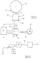
- Fig. 1 shows schematically a circuit arrangement for an immobilizer according to the Invention.
- FIG. 2 shows a circuit detail of the circuit board according to FIG. 1.
- a so-called magnet wheel 10 is shown, for example on the crankshaft the motor of a scooter or the like.
- an initiator 12 is arranged, which extends only over a certain circumferential range extends.
- the initiator 12 acts with an armature 14 of an ignition coil 16 together.
- the coil 16 generates a pulse generated, which is given to an ignition circuit 18 for generating an ignition pulse via an ignition coil, as is known per se.
- the circuit described is also already known.
- the ignition circuit described also includes an ignition lock 20, into which an ignition key 22 can be inserted.
- the coupling of the ignition lock 20 and the ignition key 22 signals that the engine is ready to start or initiates starting of the motor. In this respect, too, there is nothing special about the state of the art in front.
- circuit board 26 With the housing 24 of the ignition coil 16, a circuit board 26 is firmly cast, for example with cast resin, as indicated at 28.
- the circuit board 26 is with their Circuit components partially shown in Fig. 2.
- Interrupt switch 30 is connected, which is preferably electronic, however, this is not shown.
- the switch 30 is operated by an actuation circuit 32 actuated, which in turn receives a signal from a code detection circuit 34, which is mounted on the circuit board 26.
- a Transponder 36 With the ignition key 22 is a Transponder 36 coupled, in which a code is stored. If the key 22 in the lock 20 inserted and the lock actuated, a receive and transmit circuit occurs 40 interacts with the transponder and activates the latter Generation of a code signal received by circuit 40 and transmitted through a Line 38 is transmitted to the circuit board 26.
- a code recognition circuit reads the code of the transponder 36 on the circuit board Transponders 36 the stored code in the code recognition circuit 34, the latter generates a signal for the actuation circuit 32 (Fig. 2), which the Switch 30 closes so that the pulses of the ignition coil 16 on the ignition circuit 18 can be transferred.
- a short-circuit switch can also be provided which short-circuits the ignition coil 16 and only opens if the authorization is proven based on the code comparison is.
- a separate code carrier can also be provided, which in the vicinity or in contact with a receive and transmit circuit on the ignition lock or can be brought to another place, so that a corresponding Signal is transmitted to the circuit board 26. It is also conceivable on the circuit board 26 to arrange a receive and transmit circuit with a transponder or a similar signal transmitter serving as code carrier in interaction occurs to determine if an authorized person is about to start the engine. Instead of a contact transfer or interaction between the Code carrier and the receiving circuit is also conceivable, a contactless transmission path to be provided, for example an HF or IR link.
Landscapes
- Engineering & Computer Science (AREA)
- Mechanical Engineering (AREA)
- Lock And Its Accessories (AREA)
- Ignition Installations For Internal Combustion Engines (AREA)
- Output Control And Ontrol Of Special Type Engine (AREA)
Applications Claiming Priority (2)
| Application Number | Priority Date | Filing Date | Title |
|---|---|---|---|
| DE10006300A DE10006300C2 (de) | 2000-02-12 | 2000-02-12 | Wegfahrsperre für ein von einem Verbrennungsmotor angetriebenes Fahrzeug |
| DE10006300 | 2000-02-12 |
Publications (2)
| Publication Number | Publication Date |
|---|---|
| EP1123846A2 true EP1123846A2 (fr) | 2001-08-16 |
| EP1123846A3 EP1123846A3 (fr) | 2004-01-14 |
Family
ID=7630717
Family Applications (1)
| Application Number | Title | Priority Date | Filing Date |
|---|---|---|---|
| EP01103132A Withdrawn EP1123846A3 (fr) | 2000-02-12 | 2001-02-09 | Dispositif d'immobilisation pour véhicules à moteur à combustion |
Country Status (3)
| Country | Link |
|---|---|
| EP (1) | EP1123846A3 (fr) |
| DE (1) | DE10006300C2 (fr) |
| HK (1) | HK1041469A1 (fr) |
Families Citing this family (1)
| Publication number | Priority date | Publication date | Assignee | Title |
|---|---|---|---|---|
| DE102005039585A1 (de) | 2005-08-19 | 2007-02-22 | Daimlerchrysler Ag | Fahrberechtigungssystem mit einer elektronischen Wegfahrsperrfunktion |
Citations (1)
| Publication number | Priority date | Publication date | Assignee | Title |
|---|---|---|---|---|
| WO1997025227A1 (fr) | 1996-01-05 | 1997-07-17 | O.E.M. Project Management Limited | Dispositifs de blocage pour moteurs ou vehicules |
Family Cites Families (9)
| Publication number | Priority date | Publication date | Assignee | Title |
|---|---|---|---|---|
| US3158749A (en) * | 1960-05-06 | 1964-11-24 | Jack S Mcallister | Anti-theft device |
| US4155420A (en) * | 1977-05-12 | 1979-05-22 | Clifford Staver | Theft proof ignition system |
| IL73589A (en) * | 1984-11-21 | 1988-12-30 | Zuck Or Ltd | Vehicle theft prevention apparatus |
| FR2617779B1 (fr) * | 1987-07-09 | 1990-07-20 | Neiman Sa | Dispositif antivol de vehicules automobiles par coupure d'alimentation de l'allumage |
| GB2261026A (en) * | 1991-11-01 | 1993-05-05 | Kenneth Gardner | Preventing unauthorised use of spark ignition vehicle engines |
| DE9201084U1 (de) * | 1992-01-30 | 1992-03-12 | Selani, Silvo, 8000 München | Auto-Diebstahlstartsperre |
| US5656866A (en) * | 1995-11-22 | 1997-08-12 | Conrow; Tom | Vehicle ignition-disabling anti-car jacking device |
| IT1295450B1 (it) * | 1997-09-30 | 1999-05-12 | Magneti Marelli Spa | Sistema di accensione con funzione di immobilizzazione per un motoveicolo con generatore a volano magnete. |
| AU5929299A (en) * | 1998-07-24 | 2000-02-14 | Polydorou, Basil | Ignition coil with integrated remotely controlled immobilizer |
-
2000
- 2000-02-12 DE DE10006300A patent/DE10006300C2/de not_active Expired - Fee Related
-
2001
- 2001-02-09 EP EP01103132A patent/EP1123846A3/fr not_active Withdrawn
-
2002
- 2002-02-15 HK HK02101123.6A patent/HK1041469A1/zh unknown
Patent Citations (1)
| Publication number | Priority date | Publication date | Assignee | Title |
|---|---|---|---|---|
| WO1997025227A1 (fr) | 1996-01-05 | 1997-07-17 | O.E.M. Project Management Limited | Dispositifs de blocage pour moteurs ou vehicules |
Also Published As
| Publication number | Publication date |
|---|---|
| HK1041469A1 (zh) | 2002-07-12 |
| DE10006300A1 (de) | 2001-08-23 |
| EP1123846A3 (fr) | 2004-01-14 |
| DE10006300C2 (de) | 2002-01-10 |
Similar Documents
| Publication | Publication Date | Title |
|---|---|---|
| DE69532099T2 (de) | Schlüsselschloss-Vorrichtung | |
| DE69425795T2 (de) | Unabhängige Diebstahlschutzvorrichtung für Kraftfahrzeuge | |
| EP1045947B1 (fr) | Systeme de communication electronique | |
| DE19729402C2 (de) | Diebstahlschutzsystem für ein Kraftfahrzeug | |
| DE4434655C2 (de) | Elektronisches Zündstartschloßsystem an einem Kraftfahrzeug | |
| DE4434587B4 (de) | Elektronisches Zündstartschloßsystem an einem Kraftfahrzeug | |
| DE19943498A1 (de) | Fahrzeugschlüssel für fernbedienbare Fahrzeugschliesssysteme | |
| EP0720545A1 (fr) | SYSTèME DE SERRURE ELECTRONIQUE DE CONTACT POUR VEHICULES à MOTEUR | |
| EP1128997B1 (fr) | Systeme antivol notamment destine a des vehicules automobiles | |
| DE19641056A1 (de) | Schlüsselidentifizierungssystem | |
| DE19934188A1 (de) | Sicherheitseinrichtung für Schutzhelme | |
| EP0984124A2 (fr) | Clé électronique | |
| DE19737856A1 (de) | Diebstahlschutzsystem für ein Kraftfahrzeug | |
| DE10006300C2 (de) | Wegfahrsperre für ein von einem Verbrennungsmotor angetriebenes Fahrzeug | |
| DE102004002949B4 (de) | Wegfahrsperre für Fahrzeuge | |
| DE3043627A1 (de) | Vorrichtung zum verhindern einer unbefugten benutzung eines fahrzeuges, insbesondere eines kraftfahrzeuges | |
| DE19937915A1 (de) | Elektronischer Schlüssel | |
| EP1184237A2 (fr) | Protection de sécurité pour éviter une déconnexion d'une connexion électrique par une personne non habilitée | |
| DE10049321A1 (de) | Vorrichtung zur externen Spannungseinspeisung | |
| DE19805945C2 (de) | Schließsystem mit einem elektronischen Schlüssel, insbesondere für das Zündschloß eines Kraftfahrzeugs, sowie elektronischer Schlüssel | |
| EP1723615B1 (fr) | Composant inductif pour cle electronique | |
| DE102019114830A1 (de) | Authentifizierungssystem sowie Sicherungsverfahren hierzu | |
| DE60008538T2 (de) | Sicherheitssystem für kraftfahrzeuge | |
| DE102010061192A1 (de) | Mechanische Verriegelungsvorrichtung für ein Motorrad | |
| EP1126104B1 (fr) | Fermeture pour portes |
Legal Events
| Date | Code | Title | Description |
|---|---|---|---|
| PUAI | Public reference made under article 153(3) epc to a published international application that has entered the european phase |
Free format text: ORIGINAL CODE: 0009012 |
|
| AK | Designated contracting states |
Kind code of ref document: A2 Designated state(s): AT BE CH CY DE DK ES FI FR GB GR IE IT LI LU MC NL PT SE TR |
|
| AX | Request for extension of the european patent |
Free format text: AL;LT;LV;MK;RO;SI |
|
| PUAL | Search report despatched |
Free format text: ORIGINAL CODE: 0009013 |
|
| AK | Designated contracting states |
Kind code of ref document: A3 Designated state(s): AT BE CH CY DE DK ES FI FR GB GR IE IT LI LU MC NL PT SE TR |
|
| AX | Request for extension of the european patent |
Extension state: AL LT LV MK RO SI |
|
| AKX | Designation fees paid | ||
| REG | Reference to a national code |
Ref country code: DE Ref legal event code: 8566 |
|
| STAA | Information on the status of an ep patent application or granted ep patent |
Free format text: STATUS: THE APPLICATION IS DEEMED TO BE WITHDRAWN |
|
| 18D | Application deemed to be withdrawn |
Effective date: 20040715 |
|
| REG | Reference to a national code |
Ref country code: HK Ref legal event code: WD Ref document number: 1041469 Country of ref document: HK |