EP1123887A1 - Herstellungsverfahren für förderrollen aus papier - Google Patents
Herstellungsverfahren für förderrollen aus papier Download PDFInfo
- Publication number
- EP1123887A1 EP1123887A1 EP00953529A EP00953529A EP1123887A1 EP 1123887 A1 EP1123887 A1 EP 1123887A1 EP 00953529 A EP00953529 A EP 00953529A EP 00953529 A EP00953529 A EP 00953529A EP 1123887 A1 EP1123887 A1 EP 1123887A1
- Authority
- EP
- European Patent Office
- Prior art keywords
- rotary shaft
- paper feed
- powder
- molded body
- hydraulic
- Prior art date
- Legal status (The legal status is an assumption and is not a legal conclusion. Google has not performed a legal analysis and makes no representation as to the accuracy of the status listed.)
- Granted
Links
- 238000004519 manufacturing process Methods 0.000 title claims abstract description 11
- 239000000203 mixture Substances 0.000 claims abstract description 63
- 238000000034 method Methods 0.000 claims abstract description 32
- 239000000843 powder Substances 0.000 claims description 74
- 238000001125 extrusion Methods 0.000 claims description 22
- 239000000463 material Substances 0.000 claims description 22
- 239000011812 mixed powder Substances 0.000 claims description 19
- 229920005989 resin Polymers 0.000 claims description 16
- 239000011347 resin Substances 0.000 claims description 16
- PPBRXRYQALVLMV-UHFFFAOYSA-N Styrene Chemical compound C=CC1=CC=CC=C1 PPBRXRYQALVLMV-UHFFFAOYSA-N 0.000 claims description 14
- 229920006026 co-polymeric resin Polymers 0.000 claims description 12
- 239000002562 thickening agent Substances 0.000 claims description 10
- 239000004925 Acrylic resin Substances 0.000 claims description 8
- 229920000178 Acrylic resin Polymers 0.000 claims description 8
- XTXRWKRVRITETP-UHFFFAOYSA-N Vinyl acetate Chemical compound CC(=O)OC=C XTXRWKRVRITETP-UHFFFAOYSA-N 0.000 claims description 7
- 239000002245 particle Substances 0.000 claims description 5
- 239000000839 emulsion Substances 0.000 claims description 4
- 239000003822 epoxy resin Substances 0.000 claims description 4
- 229920000647 polyepoxide Polymers 0.000 claims description 4
- 229920006243 acrylic copolymer Polymers 0.000 claims description 3
- XLYOFNOQVPJJNP-UHFFFAOYSA-N water Substances O XLYOFNOQVPJJNP-UHFFFAOYSA-N 0.000 description 16
- 238000000465 moulding Methods 0.000 description 15
- 239000000853 adhesive Substances 0.000 description 14
- 230000001070 adhesive effect Effects 0.000 description 14
- 238000000227 grinding Methods 0.000 description 12
- 238000009472 formulation Methods 0.000 description 10
- 238000013329 compounding Methods 0.000 description 9
- 238000005520 cutting process Methods 0.000 description 9
- 230000000052 comparative effect Effects 0.000 description 8
- VYPSYNLAJGMNEJ-UHFFFAOYSA-N Silicium dioxide Chemical compound O=[Si]=O VYPSYNLAJGMNEJ-UHFFFAOYSA-N 0.000 description 7
- 239000011398 Portland cement Substances 0.000 description 6
- 230000007423 decrease Effects 0.000 description 6
- 238000011049 filling Methods 0.000 description 5
- 238000002156 mixing Methods 0.000 description 5
- 229910021487 silica fume Inorganic materials 0.000 description 5
- 239000000454 talc Substances 0.000 description 5
- 229910052623 talc Inorganic materials 0.000 description 5
- 229920002134 Carboxymethyl cellulose Polymers 0.000 description 4
- -1 calcium silicate compound Chemical class 0.000 description 4
- 238000006243 chemical reaction Methods 0.000 description 4
- 150000001875 compounds Chemical class 0.000 description 4
- 238000005469 granulation Methods 0.000 description 4
- 230000003179 granulation Effects 0.000 description 4
- 125000000391 vinyl group Chemical group [H]C([*])=C([H])[H] 0.000 description 4
- 229920002554 vinyl polymer Polymers 0.000 description 4
- OYPRJOBELJOOCE-UHFFFAOYSA-N Calcium Chemical compound [Ca] OYPRJOBELJOOCE-UHFFFAOYSA-N 0.000 description 3
- 239000000654 additive Substances 0.000 description 3
- 229910052791 calcium Inorganic materials 0.000 description 3
- 239000011575 calcium Substances 0.000 description 3
- 239000004615 ingredient Substances 0.000 description 3
- 239000000377 silicon dioxide Substances 0.000 description 3
- VTYYLEPIZMXCLO-UHFFFAOYSA-L Calcium carbonate Chemical compound [Ca+2].[O-]C([O-])=O VTYYLEPIZMXCLO-UHFFFAOYSA-L 0.000 description 2
- 230000000996 additive effect Effects 0.000 description 2
- 230000008859 change Effects 0.000 description 2
- 238000007906 compression Methods 0.000 description 2
- 230000006835 compression Effects 0.000 description 2
- 229920001577 copolymer Polymers 0.000 description 2
- 230000000694 effects Effects 0.000 description 2
- 230000002708 enhancing effect Effects 0.000 description 2
- 230000006872 improvement Effects 0.000 description 2
- 239000007769 metal material Substances 0.000 description 2
- 239000010445 mica Substances 0.000 description 2
- 229910052618 mica group Inorganic materials 0.000 description 2
- 239000000047 product Substances 0.000 description 2
- 229920006395 saturated elastomer Polymers 0.000 description 2
- 238000010008 shearing Methods 0.000 description 2
- PEXNXOXCZLFQAO-ODZAUARKSA-N (z)-but-2-enedioic acid;ethenyl acetate Chemical compound CC(=O)OC=C.OC(=O)\C=C/C(O)=O PEXNXOXCZLFQAO-ODZAUARKSA-N 0.000 description 1
- NIXOWILDQLNWCW-UHFFFAOYSA-M Acrylate Chemical compound [O-]C(=O)C=C NIXOWILDQLNWCW-UHFFFAOYSA-M 0.000 description 1
- 235000008733 Citrus aurantifolia Nutrition 0.000 description 1
- 229920001875 Ebonite Polymers 0.000 description 1
- 239000004593 Epoxy Substances 0.000 description 1
- JOYRKODLDBILNP-UHFFFAOYSA-N Ethyl urethane Chemical compound CCOC(N)=O JOYRKODLDBILNP-UHFFFAOYSA-N 0.000 description 1
- 229910000915 Free machining steel Inorganic materials 0.000 description 1
- 239000004354 Hydroxyethyl cellulose Substances 0.000 description 1
- 229920000663 Hydroxyethyl cellulose Polymers 0.000 description 1
- 229910018104 Ni-P Inorganic materials 0.000 description 1
- 229910018536 Ni—P Inorganic materials 0.000 description 1
- 235000011941 Tilia x europaea Nutrition 0.000 description 1
- 238000010521 absorption reaction Methods 0.000 description 1
- 230000002378 acidificating effect Effects 0.000 description 1
- 230000002411 adverse Effects 0.000 description 1
- 230000005540 biological transmission Effects 0.000 description 1
- 230000015572 biosynthetic process Effects 0.000 description 1
- 229910000019 calcium carbonate Inorganic materials 0.000 description 1
- AXCZMVOFGPJBDE-UHFFFAOYSA-L calcium dihydroxide Chemical compound [OH-].[OH-].[Ca+2] AXCZMVOFGPJBDE-UHFFFAOYSA-L 0.000 description 1
- 239000000920 calcium hydroxide Substances 0.000 description 1
- 229910001861 calcium hydroxide Inorganic materials 0.000 description 1
- 239000001506 calcium phosphate Substances 0.000 description 1
- 229910000389 calcium phosphate Inorganic materials 0.000 description 1
- 235000011010 calcium phosphates Nutrition 0.000 description 1
- 239000000378 calcium silicate Substances 0.000 description 1
- 229910052918 calcium silicate Inorganic materials 0.000 description 1
- OSGAYBCDTDRGGQ-UHFFFAOYSA-L calcium sulfate Chemical compound [Ca+2].[O-]S([O-])(=O)=O OSGAYBCDTDRGGQ-UHFFFAOYSA-L 0.000 description 1
- ZOMBKNNSYQHRCA-UHFFFAOYSA-J calcium sulfate hemihydrate Chemical compound O.[Ca+2].[Ca+2].[O-]S([O-])(=O)=O.[O-]S([O-])(=O)=O ZOMBKNNSYQHRCA-UHFFFAOYSA-J 0.000 description 1
- 239000001768 carboxy methyl cellulose Substances 0.000 description 1
- 235000010948 carboxy methyl cellulose Nutrition 0.000 description 1
- 239000008112 carboxymethyl-cellulose Substances 0.000 description 1
- 239000004568 cement Substances 0.000 description 1
- 239000000919 ceramic Substances 0.000 description 1
- 239000007795 chemical reaction product Substances 0.000 description 1
- 239000003795 chemical substances by application Substances 0.000 description 1
- 239000004927 clay Substances 0.000 description 1
- 238000001816 cooling Methods 0.000 description 1
- 238000005336 cracking Methods 0.000 description 1
- 150000004683 dihydrates Chemical class 0.000 description 1
- 238000004090 dissolution Methods 0.000 description 1
- 238000009826 distribution Methods 0.000 description 1
- 238000001035 drying Methods 0.000 description 1
- 229920001971 elastomer Polymers 0.000 description 1
- HDERJYVLTPVNRI-UHFFFAOYSA-N ethene;ethenyl acetate Chemical group C=C.CC(=O)OC=C HDERJYVLTPVNRI-UHFFFAOYSA-N 0.000 description 1
- 229920001038 ethylene copolymer Polymers 0.000 description 1
- 239000000945 filler Substances 0.000 description 1
- 239000010881 fly ash Substances 0.000 description 1
- 239000010440 gypsum Substances 0.000 description 1
- 229910052602 gypsum Inorganic materials 0.000 description 1
- 238000010438 heat treatment Methods 0.000 description 1
- 235000019447 hydroxyethyl cellulose Nutrition 0.000 description 1
- 238000003780 insertion Methods 0.000 description 1
- 230000037431 insertion Effects 0.000 description 1
- 239000004571 lime Substances 0.000 description 1
- HCWCAKKEBCNQJP-UHFFFAOYSA-N magnesium orthosilicate Chemical compound [Mg+2].[Mg+2].[O-][Si]([O-])([O-])[O-] HCWCAKKEBCNQJP-UHFFFAOYSA-N 0.000 description 1
- 239000000391 magnesium silicate Substances 0.000 description 1
- 229910052919 magnesium silicate Inorganic materials 0.000 description 1
- 235000019792 magnesium silicate Nutrition 0.000 description 1
- 230000007246 mechanism Effects 0.000 description 1
- 229920000609 methyl cellulose Polymers 0.000 description 1
- 239000001923 methylcellulose Substances 0.000 description 1
- 235000010981 methylcellulose Nutrition 0.000 description 1
- 239000012778 molding material Substances 0.000 description 1
- 230000002093 peripheral effect Effects 0.000 description 1
- 230000000704 physical effect Effects 0.000 description 1
- 229920005670 poly(ethylene-vinyl chloride) Polymers 0.000 description 1
- 229920001296 polysiloxane Polymers 0.000 description 1
- 238000005096 rolling process Methods 0.000 description 1
- 239000005060 rubber Substances 0.000 description 1
- 239000004576 sand Substances 0.000 description 1
- 238000005488 sandblasting Methods 0.000 description 1
- 238000007493 shaping process Methods 0.000 description 1
- 229920002545 silicone oil Polymers 0.000 description 1
- 239000002893 slag Substances 0.000 description 1
- 239000011343 solid material Substances 0.000 description 1
- 238000003756 stirring Methods 0.000 description 1
- 229920003048 styrene butadiene rubber Polymers 0.000 description 1
- 239000000126 substance Substances 0.000 description 1
- 229920003051 synthetic elastomer Polymers 0.000 description 1
- 239000005061 synthetic rubber Substances 0.000 description 1
- 229920001897 terpolymer Polymers 0.000 description 1
- 239000011800 void material Substances 0.000 description 1
- 238000003466 welding Methods 0.000 description 1
- 230000003245 working effect Effects 0.000 description 1
Images

Classifications
-
- B—PERFORMING OPERATIONS; TRANSPORTING
- B65—CONVEYING; PACKING; STORING; HANDLING THIN OR FILAMENTARY MATERIAL
- B65H—HANDLING THIN OR FILAMENTARY MATERIAL, e.g. SHEETS, WEBS, CABLES
- B65H27/00—Special constructions, e.g. surface features, of feed or guide rollers for webs
-
- B—PERFORMING OPERATIONS; TRANSPORTING
- B28—WORKING CEMENT, CLAY, OR STONE
- B28B—SHAPING CLAY OR OTHER CERAMIC COMPOSITIONS; SHAPING SLAG; SHAPING MIXTURES CONTAINING CEMENTITIOUS MATERIAL, e.g. PLASTER
- B28B23/00—Arrangements specially adapted for the production of shaped articles with elements wholly or partly embedded in the moulding material; Production of reinforced objects
-
- B—PERFORMING OPERATIONS; TRANSPORTING
- B28—WORKING CEMENT, CLAY, OR STONE
- B28B—SHAPING CLAY OR OTHER CERAMIC COMPOSITIONS; SHAPING SLAG; SHAPING MIXTURES CONTAINING CEMENTITIOUS MATERIAL, e.g. PLASTER
- B28B3/00—Producing shaped articles from the material by using presses; Presses specially adapted therefor
- B28B3/20—Producing shaped articles from the material by using presses; Presses specially adapted therefor wherein the material is extruded
-
- B—PERFORMING OPERATIONS; TRANSPORTING
- B28—WORKING CEMENT, CLAY, OR STONE
- B28B—SHAPING CLAY OR OTHER CERAMIC COMPOSITIONS; SHAPING SLAG; SHAPING MIXTURES CONTAINING CEMENTITIOUS MATERIAL, e.g. PLASTER
- B28B3/00—Producing shaped articles from the material by using presses; Presses specially adapted therefor
- B28B3/20—Producing shaped articles from the material by using presses; Presses specially adapted therefor wherein the material is extruded
- B28B3/26—Extrusion dies
- B28B3/2645—Extrusion dies using means for inserting reinforcing members
-
- B—PERFORMING OPERATIONS; TRANSPORTING
- B65—CONVEYING; PACKING; STORING; HANDLING THIN OR FILAMENTARY MATERIAL
- B65H—HANDLING THIN OR FILAMENTARY MATERIAL, e.g. SHEETS, WEBS, CABLES
- B65H2404/00—Parts for transporting or guiding the handled material
- B65H2404/10—Rollers
- B65H2404/13—Details of longitudinal profile
- B65H2404/134—Axle
- B65H2404/1342—Built-up, i.e. arrangement for mounting axle element on roller body
-
- B—PERFORMING OPERATIONS; TRANSPORTING
- B65—CONVEYING; PACKING; STORING; HANDLING THIN OR FILAMENTARY MATERIAL
- B65H—HANDLING THIN OR FILAMENTARY MATERIAL, e.g. SHEETS, WEBS, CABLES
- B65H2404/00—Parts for transporting or guiding the handled material
- B65H2404/10—Rollers
- B65H2404/13—Details of longitudinal profile
- B65H2404/135—Body
- B65H2404/1351—Pipe element
Definitions
- the present invention relates to a method for producing paper feed rollers in which a hydraulic composition is used for roller portions and which are employed in apparatuses, such as printers, facsimile machines and copying machines, requiring papers to be accurately conveyed.
- metallic rollers have been used as paper feed rollers.
- the metallic rollers have been each produced by attaching end plates with shaft portions to both end portions of a hollow metallic cylindrical body constituting a roller portion, respectively, by welding.
- a rotary shaft of the metallic roller is formed by the shaft portions at the opposite ends, there is a very difficult problem in ensuring the concentricity between the metallic cylindrical body and the rotary shaft.
- paper feed rollers in which a roller portion is constituted with hard rubber to reduce the weight have been used, but there is a problem in that errors are likely to occur in feeding papers owing to large heat expansion of the roller portion.
- Sumitomo Osaka Cement Co., Ltd. made an invention directed to a method for the production of an integrated paper feed roller by preparing a cylindrical molded body having a given length from a hydraulic composition according to a press molding method and fixing the molded body around the outer periphery of a rotary shaft, and Sumitomo Osaka Cement Co., Ltd. filed an application therefor under Japanese Patent Application No. 10-177,100. Further, Sumitomo Osaka Cement Co., Ltd. filed patent application under Japanese patent application No. 11-28,137, etc. directed to a method for the production of paper feed rollers in which roller portions are formed by connecting a plurality of cylindrical molded bodies.
- the length of the cylindrical molded bodies themselves can be shortened as compared with that of a desired roller portion, non-uniform pressure applied during the press molding can be prevented, and a shaping mold can be made smaller.
- the length of a single cylindrical body is set based on the relationship between the size of papers and the number of such cylindrical molded bodies to be connected, and a plurality of the cylindrical molded bodies having a single shape are preliminarily prepared, plural kinds of paper feed rollers can be easily produced depending upon the sizes of papers by using given numbers of the cylindrical molded bodies having a single shape. This enables the inexpensive mass production of the paper feed rollers with a high precision.
- the roller portion is formed by connecting plural cylindrical molded bodies in the above method, there is a problem in that the hardness of the roller portion is low. Further, although the rigidity can be increased by appropriately selecting an adhesive used in the connecting portion, it leads to cost-up, and there is a limit for the increase in the rigidity.
- the present invention is aimed at solving the above problems, and providing a paper feed roller-producing method capable of mass-producing, with a higher precision at a more inexpensive cost, a high-precision paper feed roller having no connecting portion at a roller portion according to an extrusion molding with use of a hydraulic composition.
- the paper feed roller-producing method is a method for producing a paper feed roller comprising a rotary shaft and a cylindrical roller portion integrated around the outer periphery of the rotary shaft, characterized in that the roller portion is formed by extruding a hydraulic composition and curing and hardening the extrudate product.
- the method (3) is most preferable.
- the hydraulic composition preferably comprises 100 wt. parts of a mixed powder, 2 to 9 wt. parts of a workability improver, and 0.5 to 5 wt. parts of a thickening agent, said mixed powder comprising 40 to 80 wt% of a hydraulic powder, 10 to 50 wt% of a non-hydraulic powder having the average particle diameter smaller than that of the hydraulic powder by an order of one digit or more, and 10 to 30 wt% of an extrusion improver
- the extrusion improver is preferably an inorganic scaly material.
- the inorganic scaly material talc and mica may be recited.
- the workability improver is preferably a powder or emulsion composed of at least one resin selected from a vinyl acetate resin or a copolymer resin with vinyl acetate, an acrylic resin or an acrylic copolymer resin, a styrene resin or a copolymer resin with styrene and an epoxy resin
- rotary shaft used in the present invention those similar to the conventional rotary shafts in the paper feed rollers may be used.
- a shaft for supporting the hollow cylindrical roller portion as a paper-feeding portion may be cut and finished to provide a bearing-fitting portion, a driving force transmission mechanism-fitting portion or the like.
- a material of the rotary shaft an ordinary material such as a SUS free cutting steel may be recited.
- the surface of the rotary shaft may be electrolessly plated with Ni-P.
- the cylindrical roller portion in the present invention is produced by extruding a cylindrical molded body from a hydraulic composition, and curing and hardening the extrudate.
- the cylindrical roller portion and the rotary shaft may be integrated by any one of the above-mentioned methods (1) to (3).
- the precision (a deviation precision) of the thus obtained cylindrical roller portion may be at a high level as it is.
- the roller portion is subjected to centerless cutting or the like, the circularity of the cylindrical roller portion can be enhanced and the concentricity between the roller portion and the rotary shaft can be improved.
- the paper feed roller with a high precision can be obtained by enhancing the circularity and the concentricity.
- the thickness of the cylindrical roller portion is determined by the outer diameter of the rotary shaft used and that of the paper feed roller.
- a tolerance of the diameter of the cylindrical roller portion is set at a given numeral value in design, which is ordinarily set at a working accuracy of a desired outer diameter of ⁇ 0.003 mm.
- the surface of the cylindrical roller portion itself may be finished coarsely by sand blasting or the like.
- the hydraulic composition used in the present invention comprises a mixed powder of a hydraulic powder, a non-hydraulic powder and an extrusion improver, a workability improver and a thickening agent.
- the composition may include other additive if necessary, and further water contained upon necessity.
- the hydraulic powder used in the present invention means a powder to be cured with water, for example, a calcium silicate compound powder, a calcium aluminate compound powder, a calcium fluoroaluminate compound powder, a calcium sulfaminate compound powder, a calcium aluminoferrite compound powder, a calcium phosphate compound powder, a hemihydrate or anhydrous gypsum powder, a self-hardening lime powder and a mixed powder of any two or more kinds of these powders may be recited.
- powder such as Portland cement may be recited.
- the Blaine's specific surface area is preferably not less than 2500 cm 2 /g from the standpoint of ensuring the hydraulic property regarding the strength of the molded body.
- the compounding amount of the hydraulic powder is 40 to 80 wt%, more preferably 45 to 55 wt%, of the mixed powder of the hydraulic powder, the non-hydraulic powder and the extrusion improver.
- the compounding amount is less than 40 wt%, the strength and the filling percentage decrease, whereas if it is more than 80 wt%, the filing percentage in obtaining the molded body decreases. Both cases are undesirable, because the molded body cannot withstand the working stress during mechanical working.
- the non-hydraulic powder means a powder which will not be cured even upon contact between water and it alone.
- the non-hydraulic powder includes powders which each form a reaction product between other dissolved ingredient through dissolution of that therefrom in an alkaline or acidic state or in a high pressure steam atmosphere.
- typical examples of the non-hydraulic powder mention may be made of calcium hydroxide powder, gypsum dihydrate powder, calcium carbonate powder, slag powder, fly ash powder, silica powder, clay powder and silica fumed powder, for example.
- the average particle diameter of the non-hydraulic powder is smaller than that of the hydraulic powder by an order of one or more digits, preferably two or more digits.
- the lower limit of the fineness of the non-hydraulic powder is not particularly set, so long as the effects of the present invention are not damaged.
- the compounding amount of the non-hydraulic powder is set at preferably 10 to 50 wt%, more preferably 20 to 30 wt% of the mixed powder comprising the hydraulic powder, the non-hydraulic powder and the extrusion improver.
- the filling percentage decreases, whereas if it is more than 50 wt%, the strength and the filling percentage decrease. Both cases are undesirable, because they adversely affect various physical properties after molding and hardening, for example, chipping during mechanical working and dimensional stability.
- the addition of the non-hydraulic powder can increase the filling percentage of the molded body during molding and decrease the void percentage of the resulting molded body.
- the extrusion improver used in the present invention is a material which improves slippage between a mold frame and the molded body during extrusion, reduces anisotropy in moldability and stabilizes the quality.
- inorganic scaly materials such as talc (hydrous magnesium silicate) and mica, for example.
- talc hydrous magnesium silicate
- mica for example.
- inorganic scaly materials have excellent orientability and impart slipping property upon the surface of the molded body, so that the quality of the molded body is stabilized.
- the compounding amount of the extrusion improver is preferably 10 to 30 wt%, more preferably 15 to 25 wt% of the mixed powder comprising the hydraulic powder, the non-hydraulic powder and the extrusion improver.
- the workability improver means a material that improves moldability, mold-releasability, cutting/grinding workability and grinding accuracy of the molded body obtained from the hydraulic composition, particularly the material that contributes to improvement in cutting/grinding workability and grinding accuracy. That is, since the workability improver functions as a molding aid during the press molding, the hydraulic composition added with the workability improver improves the moldability. Further, the workability improver reduces brittleness of the cement-based hydraulic body, so that the molded body is released from the mold during the releasing step without being damaged at all, resulting in improvement in workability. In general, the molded body obtained from the hydraulic composition as a generally brittle material exhibits a cut state of a "crack-type mechanism" in cutting. In this case, problems occur that the material is broken or chipped (including microscopical phenomena).
- the hydraulic composition in the present invention contains the workability improper, it is possible to prevent cracking and chipping of the above material to which toughness is imparted to exhibit the mechanical workability in the molded body as a solid material. That is, the workability of the molded body obtained from the hydraulic composition which has been difficult to effect mechanical workings such as cutting, grinding, etc. can be improved to the same level as that of the metallic materials with the workability improver.
- the molded body can be cut with the lather or the like and ground with a cylindrical grinder or the like as in the same manner as in the metallic materials.
- the molded body can be finely worked within an order of ⁇ m relative to a desired dimension.
- the compounding amount of the workability improver is set at 2 to 9 parts by weight, preferably 3 to 4 parts by weight, relative to 100 parts by weight of the mixed powder of the hydraulic powder, the non-hydraulic powder and the extrusion improver.
- the compounding amount of less than 2 parts by weight is not preferable, because cuttability degrades. If it is more than 9 parts by weight, both the grinding accuracy and the dimensional stability after the grinding degrade, although excellent moldability is obtained.
- the grain size is generally that discrete grains are in a diameter range of not more than 1 ⁇ m.
- a powder or an emulsion of at least one kind of resins selected from a vinyl acetate resin, a copolymer resin with vinyl acetate, acrylic resin or a copolymer with acryl, a styrene resin or a copolymer with styrene, and an epoxy resin.
- vinyl acetate copolymer resin a vinyl acetate-acryl copolymer resin, a vinyl acetate-beova copolymer resin, a vinyl acetate-beova terpolymer resin, a vinyl acetate-maleate copolymer resin, a vinyl acetate-ethylene copolymer resin, a vinyl acetate-ethylene-vinyl chloride copolymer resin, etc.
- acrylic copolymer resin an acryl-stryrene copolymer resin, an acryl-silicone copolymer resin, etc.
- styrene copolymer resin a styrene-butadiene copolymer resin may be recited.
- the thickening agent is a material that exhibits adhesion when dissolved in water. This agent is an ingredient effective for enhancing the bonding forces among the particles of the hydraulic powder and the non-hydraulic powder, maintain the shape of the molded body after molding, ensuring the water holding ability and forming a compact hardened body.
- thickening agent used in the present invention mention may be made of methyl cellulose, hydroxyethyl cellulose, carboxymethyl cellulose, etc.
- the compound amount of the thickening agent is preferably 0.5 to 5 parts by weight, preferably 3 to 4 wt. parts relative to 100 parts by weight of the mixed powder of the hydraulic powder, the non-hydraulic powder and the extrusion improver.
- the mixture comprising the hydraulic composition in the present invention may contain an aggregate, such as silica sand, as a bulk filler, at such a rate that the aggregate is 10 to 50 parts by weight, preferably 20 to 30 parts by weight relative to 100 parts by weight of the mixed powder of the hydraulic powder, the non-hydraulic powder and the extrusion improver.
- an aggregate such as silica sand, as a bulk filler
- a known ceramic molding aid may be added at a rate of 1 to 10 parts by weight, preferably 3 to 6 parts by weight relative to 100 parts by weight of the mixed powder.
- a water repellant to decrease absorption of water such as silicone oil
- a water repellant to decrease absorption of water such as silicone oil
- silicone oil may be added at a rate of 0.5 to 5 parts by weight, preferably 1 to 2 parts by weight relative to 100 parts by weight of the mixed powder.
- the molding mixture is obtained by mixing the hydraulic composition, other additive to be added if necessary, and water in an amount of not more than 30 parts by weight and preferably not more than 25 parts by weight relative to 100 parts by weight of the mixture of the hydraulic powder, the non-hydraulic powder and the extrusion improver. Water is preferably as few as possible from the standpoint of suppressing shrinkage on drying.
- the mixing method is not particularly limited.
- a mixing method or a mixer is preferred, which can afford powerful shearing stress upon the mixture. Since the average particle diameter of the non-hydraulic powder is smaller than that of the hydraulic powder by an order of not less than one digit, a time required for mixing will be very longer to obtain a uniform mixture unless the shearing mixer is used.
- the mixture may be granulated to a size suitable for a shape to be molded, following the mixing.
- the granulation may be effected by using a known method such as rolling granulation, compression granulation, stirring granulation or the like.
- a cylindrical molded body having a given length and a given outer diameter is molded from a given hydraulic composition.
- a hollow cylindrical roller molded body having a hole in a central portion through which a rotary shaft is to be passed is extruded from a hydraulic composition in (1) a case where the hollow cylindrical roller molded body is extruded, the rotary shaft is inserted through the hole of the molded body thus obtained, and the molded body is cured and hardened to integrate the rotary shaft and the roller portion and (2) a case where the hydraulic composition is molded in a hollow cylindrical form, the molded body is cured and hardened, and the rotary shaft is then inserted through the hole of the hardened body.
- extrusion molding is effected by using an ordinary extruding machine shown in Fig. 1(a), for example, and a hollow cylindrical roller molded body is obtained by cutting the extruded body in a given length.
- Fig. 1(a) 1 denotes the extruding machine, 2 a molding material, 3 a hollow cylindrical extruded body, 4 a cutter for cutting the extruded body, and R a hollow cylindrical roller molded body.
- a hollow cylindrical roller molded body is concentrically extruded around a rotary shaft from a hydraulic composition, and the molded body is cured and hardened to integrate a rotary shaft and the roller portion
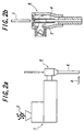
- the hydraulic composition is extruded into the roller molded body concentrically around the rotary shaft by using an extruding machine shown in Figs. 2(a) and 2(b).
- Figs. 2(a) and 2(b) 1 denotes an extruding machine having a cross head 5 fitted to a tip portion of an extruding outlet of the extruding machine.
- the rotary shaft of the paper feed roller in the present invention is inserted through and fixed in the hole, while aligned, which is formed in a central portion of the cylindrical roller portion such that the hole may be concentrically with the outer peripheral face of the cylindrical roller portion.
- the entire length of the rotary shaft, the length of the inserted portion and that of outwardly exposed portions of the rotary shaft are appropriately determined. If the rotary shaft is attached to the hole of the cylindrical roller portion with an adhesive or the like, the outer diameter of the rotary shaft is smaller than that of the inner diameter of the hole of the cylindrical molded body by around 10 to 50 ⁇ m, preferably 10 to 30 ⁇ m.
- the cylindrical molded body can be attached to the rotary shaft due to shrinkage following the hardening of the cylindrical molded body without using adhesive in combination.
- a method for producing the paper feed roller according to the present invention comprises extruding a cylindrical molded body from a hydraulic composition, and thus obtaining the cylindrical molded body.
- a rotary shaft 7 is inserted through a hole R' in the center of the cylindrical molded body R.
- the cylindrical molded body is formed such that it has strength high enough to be not broken during the insertion of the rotary shaft into the central portion of the cylindrical molded body.
- the cylindrical molded body is formed by curing and hardening, and the cylindrical roller portion is integrally formed around the outer periphery of the rotary shaft.
- a cylindrical molded body is extruded from the hydraulic composition, a hollow cylindrical roller portion is formed by curing and hardening, and then a rotary shaft is inserted through and integrally fixed with a hole of the cylindrical roller portion.
- a hollow cylindrical roller molded body is extruded concentrically around a rotary shaft from the hydraulic composition, and cured and hardened to integrate the rotary shaft and the roller portion.
- the cylindrical molded body extruded may be cured and hardened by one or any combination of ordinary temperature curing, steam curing, autoclave curing, etc. Considering the mass production, chemical stability of the products, dimensional stability, etc., autoclave curing is preferred.
- the hardening reaction of the cylindrical molded body can be completely terminated by the autoclave curing for around 5 to 10 hours, so that a dimensional change thereafter is extremely small.
- the cylindrical molded body may be fitted to the rotary shaft with the adhesive or through forming a fitting clearance by cooling the rotary shaft or heating the cylindrical molded body.
- the rotary shaft may be press fitted into the hole of the cylindrical molded body.
- the adhesive an epoxy-based adhesive, an urethane-based adhesive, an emulsion-based adhesive, a synthetic rubber-based adhesive, an acrylate-based adhesive or the like is used.
- the cylindrical molded body dimensionally shrinks by 0.08 to 0.15 % (depending upon the compounding condition) through curing with the autoclave, the inner diameter portion of the cylindrical molded body is formed, taking the shrinkage amount into consideration.
- the molded body may be left at room temperature as it is or cured in water or cured with steam. Curing in the autoclave is preferred. If water is lacking or insufficient for forming the hardened body, steam curing is preferred. Particularly, curing in the autoclave is preferred.
- the autoclave curing is effected at 165°C or higher under a saturated steam pressure of 7.15 kg/cm 2 , preferably a saturated steam pressure of 9.10 kg/cm 2 or higher.
- the curing time depends upon the curing temperature, and is 5 to 15 hours at 175°C. After the press molding, the molded body preferably exhibits compression strength of around 5 N/mm 2 before starting the autoclave curing. If the molded body does not exhibit sufficient strength before the autoclave curing, the molded body will be cracked.
- Fig. 2 is a sectional view of the extruding.
- a hydraulic composition was extruded by the method shown in Fig. 1, and cut in a given length, thereby obtaining a cylindrical roller molded body having a hole in a central portion thereof.
- a paper feed roller was produced by curing and hardening the molded in the autoclave curing and thus integrally fixing the roller portion around the outer periphery of the rotary shaft.
- the paper feed roller portion shrunk by about 0.2%, and fixed around the outer periphery of the rotary shaft.
- the materials used and dimensions were as follows.
- the hydraulic composition had the following formulation, and was mixed by a kneader.
- a hydraulic composition was extruded by the method shown in Fig. 1, and cut in a given length, thereby obtaining a cylindrical roller molded body having a hole in a central portion thereof.
- a cylindrical roller portion was formed by subjecting the molded body to reaction hardening in autoclave curing, and a rotary shaft was inserted through a hole of the roller portion.
- a paper feed roller was produced by integrating and fixing the roller portion around the outer periphery of the rotary shaft with an adhesive.
- a clearance between the hole of the hardened cylindrical roller portion and the outer periphery of the rotary shaft was around 20 ⁇ m.
- the materials used and dimensions were almost the same as in Example 1.
- the hydraulic composition had the following formulation, and was mixed by a kneader.
- a hydraulic composition was extruded around the outer periphery of a rotary shaft by using the method shown in Fig. 2, and a cylindrical roller molded body, which had a given length and a hole in a central portion thereof, was integrally formed around the outer periphery of the rotary shaft by cutting opposite end portions of the extruded body.
- the roller portion was formed by reaction hardening in the autoclave curing. Materials used and dimensions were almost the same as those in Example 1.
- the hydraulic composition had the following formulation, and was mixed by a kneader.
- the hydraulic composition had the following formulation, and was mixed by a Henschel mixer.
- roller portion units were formed by reaction hardening the molded body units in the autoclave curing.
- a rotary shaft was inserted through the holes of the roller portion units, and a paper feed roller was produced by integrating and fixing the roller portion around the outer periphery of the rotary shaft with an adhesive.
- a clearance was about 20 ⁇ m between the hole of the hardened roller portion and the outer periphery of the rotary shaft.
- Materials used and dimensions were the same as those in Example 1 except that the length of the molded body unit was 54 mm.
- the hydraulic composition had the following formulation, and was mixed by a Henschel mixer.
- the paper feed rollers in Examples 1 to 3 according to the present invention in which the extruded roller portion is integrated and fixed around the outer periphery of the rotary shaft exhibited had smaller warped amounts and thus higher rigidity.
- the paper feed rollers in Comparative Examples 1 and 2 in which the roller portion is formed in a divided manner and integrated and fixed around the outer periphery of the rotary shaft, while being connected together had larger warped amounts and thus smaller rigidity.
- the paper feed roller having high rigidity with no connecting portion in the roller portion can be mass produced less inexpensively with a high precision by extruding the hydraulic composition used.
Landscapes
- Engineering & Computer Science (AREA)
- Manufacturing & Machinery (AREA)
- Chemical & Material Sciences (AREA)
- Ceramic Engineering (AREA)
- Mechanical Engineering (AREA)
- Press-Shaping Or Shaping Using Conveyers (AREA)
- Delivering By Means Of Belts And Rollers (AREA)
- Registering, Tensioning, Guiding Webs, And Rollers Therefor (AREA)
Applications Claiming Priority (3)
| Application Number | Priority Date | Filing Date | Title |
|---|---|---|---|
| JP11233636A JP3054417B1 (ja) | 1999-08-20 | 1999-08-20 | 紙送りロ―ラの製造方法 |
| JP23363699 | 1999-08-20 | ||
| PCT/JP2000/005579 WO2001014230A1 (fr) | 1999-08-20 | 2000-08-21 | Procede de production de cylindres d'alimentation en papier |
Publications (3)
| Publication Number | Publication Date |
|---|---|
| EP1123887A1 true EP1123887A1 (de) | 2001-08-16 |
| EP1123887A4 EP1123887A4 (de) | 2006-11-02 |
| EP1123887B1 EP1123887B1 (de) | 2009-07-22 |
Family
ID=16958155
Family Applications (1)
| Application Number | Title | Priority Date | Filing Date |
|---|---|---|---|
| EP00953529A Expired - Lifetime EP1123887B1 (de) | 1999-08-20 | 2000-08-21 | Herstellungsverfahren für förderrollen aus papier |
Country Status (7)
| Country | Link |
|---|---|
| US (1) | US6758995B1 (de) |
| EP (1) | EP1123887B1 (de) |
| JP (1) | JP3054417B1 (de) |
| KR (1) | KR100412962B1 (de) |
| DE (1) | DE60042584D1 (de) |
| ID (1) | ID29485A (de) |
| WO (1) | WO2001014230A1 (de) |
Cited By (2)
| Publication number | Priority date | Publication date | Assignee | Title |
|---|---|---|---|---|
| EP3974079A1 (de) * | 2020-09-25 | 2022-03-30 | Zehnder & Sommer AG | Rohrwalze, walzenvorschub und verfahren zur herstellung einer rohrwalze |
| DE202022001624U1 (de) | 2022-02-28 | 2022-08-08 | Zehnder & Sommer Ag | Walzenvorschub mit Rohrwalze und vereinfachtem Ein-/Ausbau |
Families Citing this family (3)
| Publication number | Priority date | Publication date | Assignee | Title |
|---|---|---|---|---|
| JP4349775B2 (ja) * | 2001-12-12 | 2009-10-21 | 住友大阪セメント株式会社 | 熱可塑性水硬性組成物の成形体及び該成形体の製造方法 |
| US20050015986A1 (en) * | 2002-12-17 | 2005-01-27 | Stebnicki James C. | Method of making a return roller |
| JP5893195B2 (ja) * | 2015-05-22 | 2016-03-23 | サンコール株式会社 | 段付き排紙ローラの製造方法 |
Family Cites Families (17)
| Publication number | Priority date | Publication date | Assignee | Title |
|---|---|---|---|---|
| US3880664A (en) * | 1971-08-05 | 1975-04-29 | Herbert C Schulze | Method for extrusion |
| US3720808A (en) * | 1971-11-08 | 1973-03-13 | Gen Binding Corp | Ceramic core laminating roll |
| US3971115A (en) * | 1972-07-01 | 1976-07-27 | Agfa-Gevaert, A.G. | Method of making roller |
| US3929957A (en) * | 1975-03-05 | 1975-12-30 | Dayco Corp | Method for producing a continuous flexible reinforced tubular conduit |
| DE2731612C2 (de) * | 1976-07-22 | 1982-09-16 | Société Européenne des Produits Réfractaires, 92200 Neuilly-sur-Seine | Zementmischungen |
| US4349398A (en) * | 1980-12-08 | 1982-09-14 | Edward C. Kearns | Protective coating system |
| EP0067456B2 (de) * | 1981-06-16 | 1990-03-28 | Dansk Eternit-Fabrik A/S | Walzverfahren zur Herstellung von Gegenständen aus plastisch verformbarem Material |
| US4398960A (en) * | 1982-01-04 | 1983-08-16 | Conger/Murray Systems, Inc. | Concrete mixes |
| US4863541A (en) * | 1984-08-28 | 1989-09-05 | Cable Technology Laboratories, Inc. | Apparatus and method for manufacturing heat-shrinkable sleeve using solid core |
| US5026451A (en) * | 1988-05-12 | 1991-06-25 | Shaw Industries Ltd. | Method and apparatus for applying thermo-plastic protective coating to pipes |
| NZ226585A (en) * | 1988-10-14 | 1992-04-28 | Fibre Cement Technology Ltd | Ferrocement panels shifted off conveyor with mortar in plastic state |
| US5227105A (en) * | 1989-03-10 | 1993-07-13 | The Carborundum Company | Process for manufacturing ceramic tubes |
| US5151147A (en) * | 1990-08-17 | 1992-09-29 | Reynolds Metals Company | Coated article production system |
| US5439416A (en) * | 1990-12-24 | 1995-08-08 | Xerox Corporation | Composite shaft with integrally molded functional feature |
| US5545297A (en) * | 1992-08-11 | 1996-08-13 | E. Khashoggi Industries | Methods for continuously placing filaments within hydraulically settable compositions being extruded into articles of manufacture |
| JPH08164510A (ja) * | 1994-12-15 | 1996-06-25 | Nippon Steel Corp | ロッド状補強材挿入用押出成形装置 |
| JPH1052951A (ja) | 1996-08-12 | 1998-02-24 | Chichibu Concrete Kogyo Kk | プラテンの製造方法 |
-
1999
- 1999-08-20 JP JP11233636A patent/JP3054417B1/ja not_active Expired - Fee Related
-
2000
- 2000-08-21 DE DE60042584T patent/DE60042584D1/de not_active Expired - Lifetime
- 2000-08-21 ID IDW00200100989A patent/ID29485A/id unknown
- 2000-08-21 WO PCT/JP2000/005579 patent/WO2001014230A1/ja not_active Ceased
- 2000-08-21 US US09/807,813 patent/US6758995B1/en not_active Expired - Fee Related
- 2000-08-21 EP EP00953529A patent/EP1123887B1/de not_active Expired - Lifetime
- 2000-08-21 KR KR10-2001-7004839A patent/KR100412962B1/ko not_active Expired - Fee Related
Cited By (4)
| Publication number | Priority date | Publication date | Assignee | Title |
|---|---|---|---|---|
| EP3974079A1 (de) * | 2020-09-25 | 2022-03-30 | Zehnder & Sommer AG | Rohrwalze, walzenvorschub und verfahren zur herstellung einer rohrwalze |
| WO2022064040A1 (de) * | 2020-09-25 | 2022-03-31 | Zehnder & Sommer Ag | Rohrwalze, walzenvorschub und verfahren zur herstellung einer rohrwalze |
| DE202022001624U1 (de) | 2022-02-28 | 2022-08-08 | Zehnder & Sommer Ag | Walzenvorschub mit Rohrwalze und vereinfachtem Ein-/Ausbau |
| US12145818B2 (en) | 2022-02-28 | 2024-11-19 | Zehnder & Sommer Ag | Roll feed with tube roll and simplified mounting/dismounting |
Also Published As
| Publication number | Publication date |
|---|---|
| KR20010080218A (ko) | 2001-08-22 |
| WO2001014230A1 (fr) | 2001-03-01 |
| JP3054417B1 (ja) | 2000-06-19 |
| DE60042584D1 (de) | 2009-09-03 |
| US6758995B1 (en) | 2004-07-06 |
| KR100412962B1 (ko) | 2003-12-31 |
| EP1123887A4 (de) | 2006-11-02 |
| EP1123887B1 (de) | 2009-07-22 |
| ID29485A (id) | 2001-08-30 |
| JP2001058737A (ja) | 2001-03-06 |
Similar Documents
| Publication | Publication Date | Title |
|---|---|---|
| US6843761B1 (en) | Paper feed roller and method of manufacture | |
| US6758995B1 (en) | Production method for paper feed roller | |
| CN101351418B (zh) | 用于挤出模塑的胶合剂基组合物、其制造方法和胶合剂产品 | |
| JP2999765B1 (ja) | 紙送りロ―ラ及びその製造方法 | |
| JP2011057521A (ja) | セメント系押出成形用組成物及びセメント製品 | |
| JP3012234B1 (ja) | 紙送りロ―ラ及びその製造方法 | |
| CN1976881B (zh) | 水泥类挤压成形用组合物及其制品 | |
| JP3227127B2 (ja) | 水硬性組成物及びそれを用いた成形体 | |
| JP4533316B2 (ja) | セメント系押出成形用組成物 | |
| JP2004011703A (ja) | 断熱ローラ及びその製造方法 | |
| JPH10330146A (ja) | 水硬性無機質成形体の製造方法 | |
| JP2724618B2 (ja) | 高強度複合材料、及びその製造方法 | |
| JP2008194881A (ja) | コンクリート製品の製造方法およびコンクリート製品 | |
| JP3238900B2 (ja) | 紙送りローラ | |
| JP2002080139A (ja) | 紙送りローラおよびその製造方法 | |
| JP2004142208A (ja) | 押出中空パイプの製造方法及び中空パイプ | |
| JPH0159083B2 (de) | ||
| JP2004010387A (ja) | 水硬性組成物からなる機械部品及びその製造方法 | |
| JPH07106575B2 (ja) | 高強度セメント製成形型 | |
| JPH0469110B2 (de) | ||
| JP2001026484A (ja) | 水硬性組成物成形体 | |
| JPH062613B2 (ja) | 中空状のオートクレーブ養生押出成形用組成物 | |
| JPH0776013A (ja) | 屋根瓦の製造方法 | |
| JPH0789756A (ja) | セメント質組成物及びその製品 | |
| JP2002362984A (ja) | 窯業系外壁材の製造方法 |
Legal Events
| Date | Code | Title | Description |
|---|---|---|---|
| PUAI | Public reference made under article 153(3) epc to a published international application that has entered the european phase |
Free format text: ORIGINAL CODE: 0009012 |
|
| 17P | Request for examination filed |
Effective date: 20010419 |
|
| AK | Designated contracting states |
Kind code of ref document: A1 Designated state(s): AT BE CH CY DE DK ES FI FR GB GR IE IT LI LU MC NL PT SE |
|
| AX | Request for extension of the european patent |
Free format text: AL;LT;LV;MK;RO;SI |
|
| RBV | Designated contracting states (corrected) |
Designated state(s): DE FR GB IT |
|
| A4 | Supplementary search report drawn up and despatched |
Effective date: 20060928 |
|
| 17Q | First examination report despatched |
Effective date: 20070112 |
|
| GRAP | Despatch of communication of intention to grant a patent |
Free format text: ORIGINAL CODE: EPIDOSNIGR1 |
|
| GRAS | Grant fee paid |
Free format text: ORIGINAL CODE: EPIDOSNIGR3 |
|
| GRAA | (expected) grant |
Free format text: ORIGINAL CODE: 0009210 |
|
| AK | Designated contracting states |
Kind code of ref document: B1 Designated state(s): DE FR GB IT |
|
| REG | Reference to a national code |
Ref country code: GB Ref legal event code: FG4D |
|
| REF | Corresponds to: |
Ref document number: 60042584 Country of ref document: DE Date of ref document: 20090903 Kind code of ref document: P |
|
| PGFP | Annual fee paid to national office [announced via postgrant information from national office to epo] |
Ref country code: GB Payment date: 20090826 Year of fee payment: 10 |
|
| PGFP | Annual fee paid to national office [announced via postgrant information from national office to epo] |
Ref country code: DE Payment date: 20090929 Year of fee payment: 10 |
|
| PGFP | Annual fee paid to national office [announced via postgrant information from national office to epo] |
Ref country code: IT Payment date: 20090812 Year of fee payment: 10 |
|
| PLBE | No opposition filed within time limit |
Free format text: ORIGINAL CODE: 0009261 |
|
| STAA | Information on the status of an ep patent application or granted ep patent |
Free format text: STATUS: NO OPPOSITION FILED WITHIN TIME LIMIT |
|
| 26N | No opposition filed |
Effective date: 20100423 |
|
| GBPC | Gb: european patent ceased through non-payment of renewal fee |
Effective date: 20100821 |
|
| REG | Reference to a national code |
Ref country code: FR Ref legal event code: ST Effective date: 20110502 |
|
| PG25 | Lapsed in a contracting state [announced via postgrant information from national office to epo] |
Ref country code: IT Free format text: LAPSE BECAUSE OF NON-PAYMENT OF DUE FEES Effective date: 20100821 |
|
| REG | Reference to a national code |
Ref country code: DE Ref legal event code: R119 Ref document number: 60042584 Country of ref document: DE Effective date: 20110301 |
|
| PG25 | Lapsed in a contracting state [announced via postgrant information from national office to epo] |
Ref country code: DE Free format text: LAPSE BECAUSE OF NON-PAYMENT OF DUE FEES Effective date: 20110301 Ref country code: FR Free format text: LAPSE BECAUSE OF NON-PAYMENT OF DUE FEES Effective date: 20100831 |
|
| PG25 | Lapsed in a contracting state [announced via postgrant information from national office to epo] |
Ref country code: GB Free format text: LAPSE BECAUSE OF NON-PAYMENT OF DUE FEES Effective date: 20100821 |
|
| PGFP | Annual fee paid to national office [announced via postgrant information from national office to epo] |
Ref country code: FR Payment date: 20090909 Year of fee payment: 10 |