EP1124014B1 - Beton-Wandelement für ein Rückhaltesystem auf Strassen - Google Patents
Beton-Wandelement für ein Rückhaltesystem auf Strassen Download PDFInfo
- Publication number
- EP1124014B1 EP1124014B1 EP00890369A EP00890369A EP1124014B1 EP 1124014 B1 EP1124014 B1 EP 1124014B1 EP 00890369 A EP00890369 A EP 00890369A EP 00890369 A EP00890369 A EP 00890369A EP 1124014 B1 EP1124014 B1 EP 1124014B1
- Authority
- EP
- European Patent Office
- Prior art keywords
- wall
- elements
- wall element
- wall elements
- coupling
- Prior art date
- Legal status (The legal status is an assumption and is not a legal conclusion. Google has not performed a legal analysis and makes no representation as to the accuracy of the status listed.)
- Expired - Lifetime
Links
- 230000008878 coupling Effects 0.000 claims description 18
- 238000010168 coupling process Methods 0.000 claims description 18
- 238000005859 coupling reaction Methods 0.000 claims description 18
- 238000010079 rubber tapping Methods 0.000 claims 5
- 229910000831 Steel Inorganic materials 0.000 abstract description 9
- 239000010959 steel Substances 0.000 abstract description 9
- 238000006073 displacement reaction Methods 0.000 description 3
- 239000002184 metal Substances 0.000 description 3
- 230000001154 acute effect Effects 0.000 description 2
- 229920001971 elastomer Polymers 0.000 description 2
- 239000000806 elastomer Substances 0.000 description 2
- 238000000926 separation method Methods 0.000 description 2
- 239000000758 substrate Substances 0.000 description 2
- 238000004873 anchoring Methods 0.000 description 1
- 239000010426 asphalt Substances 0.000 description 1
- 238000010276 construction Methods 0.000 description 1
- 238000007796 conventional method Methods 0.000 description 1
- 230000009977 dual effect Effects 0.000 description 1
- 239000013013 elastic material Substances 0.000 description 1
- 238000005516 engineering process Methods 0.000 description 1
- 230000002349 favourable effect Effects 0.000 description 1
- 235000019589 hardness Nutrition 0.000 description 1
- 238000009434 installation Methods 0.000 description 1
- 238000004519 manufacturing process Methods 0.000 description 1
- 239000000463 material Substances 0.000 description 1
- 239000003973 paint Substances 0.000 description 1
- 230000002787 reinforcement Effects 0.000 description 1
Images


Classifications
-
- E—FIXED CONSTRUCTIONS
- E01—CONSTRUCTION OF ROADS, RAILWAYS, OR BRIDGES
- E01F—ADDITIONAL WORK, SUCH AS EQUIPPING ROADS OR THE CONSTRUCTION OF PLATFORMS, HELICOPTER LANDING STAGES, SIGNS, SNOW FENCES, OR THE LIKE
- E01F15/00—Safety arrangements for slowing, redirecting or stopping errant vehicles, e.g. guard posts or bollards; Arrangements for reducing damage to roadside structures due to vehicular impact
- E01F15/02—Continuous barriers extending along roads or between traffic lanes
- E01F15/08—Continuous barriers extending along roads or between traffic lanes essentially made of walls or wall-like elements ; Cable-linked blocks
- E01F15/088—Details of element connection
-
- E—FIXED CONSTRUCTIONS
- E01—CONSTRUCTION OF ROADS, RAILWAYS, OR BRIDGES
- E01F—ADDITIONAL WORK, SUCH AS EQUIPPING ROADS OR THE CONSTRUCTION OF PLATFORMS, HELICOPTER LANDING STAGES, SIGNS, SNOW FENCES, OR THE LIKE
- E01F15/00—Safety arrangements for slowing, redirecting or stopping errant vehicles, e.g. guard posts or bollards; Arrangements for reducing damage to roadside structures due to vehicular impact
- E01F15/02—Continuous barriers extending along roads or between traffic lanes
- E01F15/08—Continuous barriers extending along roads or between traffic lanes essentially made of walls or wall-like elements ; Cable-linked blocks
- E01F15/081—Continuous barriers extending along roads or between traffic lanes essentially made of walls or wall-like elements ; Cable-linked blocks characterised by the use of a specific material
- E01F15/083—Continuous barriers extending along roads or between traffic lanes essentially made of walls or wall-like elements ; Cable-linked blocks characterised by the use of a specific material using concrete
Definitions
- the invention relates to a baffle for traffic routes with concrete wall elements for a restraint system on roads.
- a separation of the oncoming traffic areas can be done by the known wall elements, but from a certain lane width, these are no longer used, since they take too high an effective deployment width to complete. In such cases, many road operators are forced to resort to conventional methods, such as e.g. use dual guidelines to separate different lanes. However, as has been shown, these safety measures are far from sufficient to avoid road accidents.
- Known wall elements made of metal can be made relatively narrow, but they are significantly more resilient than Betoiu wall elements.
- the increased stability of the wall elements against tilting caused by the lateral support elements makes it possible to produce the wall element from concrete and thus to ensure an increased mechanical strength thereof with a relatively small width. This can be dispensed with an otherwise usual in New Jersey concrete wall profiles cross-sectional widening in the lower area, which increases the field of application of the wall element according to the invention accordingly.
- a design and manufacturing technology favorable embodiment of the wall element may be to form the cross section of the wall element trapezoidal.
- a high resistance with relatively low weight of the wall element can be achieved if the support elements are formed of metal.
- On the top of the Supporting elements may be provided a bottom marking in the form of a film or a paint.
- the support elements are formed by steel profiles and anchored in the wall element.
- the anchoring in the wall element provides a very secure connection between the support elements and wall element.
- a further variant may consist in that the steel profiles have L-shaped cross-section, wherein the shorter leg L each adjacent to a recessed beveled surface of the wall member and the longer leg of L projecting directed from the wall element at an acute angle to the ground, so that - seen in cross section - the profile ends of the L-shaped steel profiles support the wall element on the ground.
- the thus connected to the wall element steel profiles provide a stable support in the lower region of the wall element, so that tipping of the wall element can be effectively avoided.
- the profiled design on the one hand saves material and is also suitable to provide additional elastic bearings.
- the bearing elements can be positively inserted into the cavity formed by the supporting elements and form parallel surfaces to the underside of the wall element.
- the wall elements are resiliently on the bearing elements, which are compressed in a collision accident so far that the support elements come into contact with the ground and act against tipping of the wall element.
- bearing elements can withstand the pressure acting on them, if, according to a further embodiment of the invention, bearing elements are designed as elastomer bearing elements.
- the bearing surfaces of the bearing elements can have a profile, preferably with a triangular cross-section, which increases the friction of the bearing elements on the substrate.
- a sufficient elastic support can be provided if the bearing elements are arranged on opposite sides and in the region of the ends of the wall element.
- the invention relates to a baffle for traffic routes, with concrete wall elements having inner drawstrings, the ends of which are provided with frontal engagement elements, in which coupling tension members for non-positive connection of adjacent wall elements are used.
- Such a baffle has already become known from AT 405 851 B- It discloses a baffle in which tension members are arranged in the connecting regions of two wall elements between the end faces, which connect the individual wall elements.
- the mutually end-side connected wall elements are deflected at a lateral approach by a motor vehicle depending on the force of the impact, which is given at the accident site itself, of course, the largest deflection.
- the object of the invention is therefore to protect the baffle from excessive deflection.
- the coupling pressure members put the coupling tension members under tension, whereby an optimal non-positive tension connection between the wall elements of the baffle according to the invention can be achieved without play, which results in a lateral impact of a motor vehicle, a smaller displacement or deflection.
- the lower shift in accidents can reduce consequential accidents in the oncoming traffic.
- the coupling-pressure members are formed by threaded screws with a shank part and a head part, and in each case one end face of each wall member, a threaded sleeve is inserted, in which the threaded screws are screwed, so that the head part of the threaded screws can be supported on the respective opposite end face of the adjacent wall element.
- the coupling pressure members are formed by threaded screws with a shank portion and a head portion, wherein the head portion is connected to a support plate, and the coupling pressure members are inserted into recesses on opposite end faces of the wall elements, wherein in each case a sleeve for receiving the shank end of the threaded screw and for supporting a threaded nut screwed onto the shaft part is provided and the support plate is supported on the inner wall of the respective opposite recess in each case.
- the pressure acting on the wall elements via the coupling pressure members can be introduced uniformly into these.
- Another embodiment of the invention may consist in that in the region of the joint between the end faces of adjacent wall elements in each case at least one planar, elastic pressure compensation element is arranged in a form-fitting manner.
- the shape of the pressure compensation element is adapted to the course of the shorter L-leg.
- the pressure compensation element is wedge-shaped, since it is better adapted to the shape of the gap occurring between the wall elements.
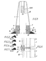
- the invention shows a concrete wall element 1 for a restraint system on roads with trapezoidal cross-section, which can be connected by means of respective frontally arranged engagement elements 15, 16 with other similar wall elements to build a restraint system.
- the invention provides that on opposite longitudinal sides in the support region of the wall element 1 at least partially along the length of metal support members 10, 11 are provided, which are non-positively connected to the wall element 1.
- the wall element is replaced by a comparable with the usual New Jersey profile stability and can thus be used as a wall element with limited roadway width.
- the support elements are formed in the embodiment of Figure 1 by over the entire length of the wall member 1 extending steel sections 10, 11 with L-shaped cross-section and anchored in the wall element 1 by anchor bolt 8, which can also be connected to the reinforcement of the wall element 1.
- anchor bolt 8 which can also be connected to the reinforcement of the wall element 1.
- any changes in the shape of the support elements are possible.
- the shorter leg 81 each adjoins a recessed beveled surface of the wall element 1 and the longer L-leg 80 projects from the wall element 1 at an acute angle to the ground, so - seen in cross-section - the profile ends of the L-shaped steel profiles the wall element 1 on the ground, as soon as it is exposed to a load in a start-up event.
- Other elastic materials can also be used to form the bearing elements.
- the bearing elements 4, 5 are positively inserted into the cavity formed by the support elements 10, 11 and form parallel to the bottom of the wall element 1 flat surfaces.
- the bearing elements cause on the one hand an elastic mounting of the wall element, whereby a depression of the same in the ground or ground, e.g. into the asphalt surface, when it warms up and softens in summer, is prevented.
- Another advantage is the increased friction by the bearing elements, which opposes a displacement of the wall element 1 in a lateral impact of a motor vehicle, an increased resistance.
- FIGS. 2, 3, 4 and 5 show further embodiments of elastic support elements 40, 50, 41, 51, 42, 52, 43, 53, whose standing surfaces have a profile which offers advantages for different substrates.
- the profiling is triangular jagged.
- the footprint of the support member shown there is slightly rounded.
- the elastic bearing elements 4, 5 are preferably arranged on opposite sides and in the region of the ends of the wall element 1.
- the dimensioning of the elastic bearing elements 4, 5 takes place in dependence on the weight of the wall element 1 and in dependence on the desired friction values.
- a vote may e.g. done by different Shore hardnesses and / or lengths of the bearing elements.
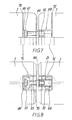
- FIG. 9 shows a detail of a guide wall for traffic routes for which the support elements 10, 11 according to the invention can be used.
- the wall elements 1,1 ' have inside the same extending drawstrings 34, 35 and 34', 35 ', whose ends are provided with end-side engaging elements 15 and 15', in which coupling tension members 21 for non-positive connection of adjacent wall elements 1, 1 'are used.
- the invention provides that the respective adjacent wall elements 1, 1 'additionally by coupling pressure members 55, 57th are connected, which are supported in or on opposite end faces of the wall elements 1, 1 '.
- the coupling pressure members are formed by threaded screws with a shaft portion 55 and a head portion 57 and in each case one end face of each wall element 1, 1 ', a threaded sleeve 56 is inserted.
- a threaded sleeve 56 is inserted in Figure 9, the corresponding end face of the wall element 1 is shown in the threaded sleeve 56, the threaded screw 55, 57 is screwed.
- the head portion 57 of the threaded screws is supported on the respective opposite end face of the adjacent wall element 1 '.
- the coupling tension member 21 can be set under a slight bias and the game of train connection can be reduced, whereby the stability of the train can be increased against lateral deflection.
- the coupling-pressure members can also be provided with guide walls with wall elements without lateral support elements.
- the coupling-pressure members of the baffle according to the invention are formed by threaded screws with a shaft portion 65 and a head portion 67 which is connected to a support plate 69 which on a reinforced by a steel core inner wall 70 of two opposite each Wells is supported.
- a sleeve 68 for receiving the shank end of the threaded screw and for supporting a screwed onto the shaft part 65 threaded nut 66 is provided.
- the clutch pressure members may be installed below or above the Kupplungslemente 21.
- At least one planar, elastic pressure compensation element 6, 7 is in each case arranged in a form-fitting manner, which is depicted in FIGS. 1 and 6, which has a wedge-shaped cross section and thereby damaging the wall elements when deflecting them avoid during a lateral startup or at least reduce, so that the baffle according to the invention can also be used after a displacement caused by a motor vehicle.
- the shape of the pressure compensation element 6, 7 is adapted to the course of the shorter L-leg 81.
Landscapes
- Engineering & Computer Science (AREA)
- Architecture (AREA)
- Civil Engineering (AREA)
- Structural Engineering (AREA)
- Refuge Islands, Traffic Blockers, Or Guard Fence (AREA)
- Road Signs Or Road Markings (AREA)
- Road Paving Structures (AREA)
- Fencing (AREA)
Description
- Die Erfindung betrifft eine Leitwand für Verkehrswege mit Beton-Wandelementen für ein Rückhaltesystem auf Straßen.
- Mit Wandelementen der vorgenannten Art kann eine wirkungsvolle Trennung von Verkehrsströmen vor allem im Gegenverkehrsbereich erreicht werden, die im Gegensatz zu einfachen Bodenmarkierungen auch eine mechanisch wirkende Begrenzung der Fahrbahnen darstellt. In vielen Bereichen ist es keineswegs ausreichend, die Kraftfahrzeuge nur durch die Farbmarkierungen vor einer gegenseitigen Beeinflussung zu schützen, da es auf stark befahrenen Strecken zu gefährlichen Verkehrssituationen kommen kann. Besonders innerhalb von Baustellenbereichen ist eine vorübergehende Verengung der zur Verfügung stehenden Straßenfläche unumgänglich. Die Kraftfahrzeuglenker neigen aber gerade an diesen Engstellen zu besonders hoher Unfallhäufigkeit, weil die vorherrschende Verkehrssituation oft unterschätzt und das eigene Fahrkönnen überschätzt wird. Auch Übermüdungen der Kraftfahrzeuglenker führen besonders an diesen engen Stellen des Verkehrsweges zu hohen Unfallgefahren.
- Eine Trennung der Gegenverkehrsbereiche kann durch die bekannten Wandelemente erfolgen, ab einer bestimmten Fahrbahnbreite sind diese aber nicht mehr einsetzbar, da sie eine zu hohe wirksame Aufstellungsbreite in Anspruch nehmen. In solchen Fällen sind viele Straßenbetreiber dazu gezwungen, auf herkömmliche Methoden, wie z.B. doppelte Leitlinien zurückzugreifen, um unterschiedliche Fahrbahnen voneinander zu trennen. Wie sich aber gezeigt hat, sind diese Sicherheitsmaßnahmen bei weitem nicht ausreichend, um Straßenverkehrsunfälle zu vermeiden.
- Bekannte Wandelemente aus Metall können relativ schmal ausgebildet werden, sie sind aber wesentlich geringfügig belastbarer als Betoiu-Wandelemente.
- Es ist daher wünschenswert, ein Wandelement der eingangs genannten Art anzugeben, das eine ausreichend stabile Aufstellung bei relativ geringer wirksamer Breite ermöglicht.
- Dies wird dadurch erreicht, daß an gegenüberliegenden Längsseiten im Auflagebereich des Wandelements zumindest teilweise entlang dessen Länge Abstützelemente vorgesehen sind, die mit dem Wandelement kraftschlüssig verbunden sind.
- Die durch die seitlichen Abstützelemente bewirkte erhöhte Stabilität der Wandelemente gegen ein Umkippen ermöglicht es, das Wandelement aus Beton herzustellen und damit eine erhöhte mechanische Festigkeit desselben bei einer relativ geringen Breite zu gewährleisten. Damit kann auf eine sonst bei New-Jersey-Betonwandprofilen übliche Querschnittsverbreiterung im unteren Bereich verzichtet werden, was das Anwendungsgebiet des erfindungsgemäßen Wandelements entsprechend erhöht.
- Eine baulich sowie herstellungstechnisch günstige Ausführungsform des Wandelements kann darin bestehen, den Querschnitt des Wandelements trapezförmig auszubilden.
- Eine hohe Widerstandsfähigkeit bei relativ geringem Gewicht des Wandelements kann dann erzielt werden, wenn die Abstützelemente aus Metall gebildet sind. Auf der Oberseite der Abstützelemente kann eine Bodenmarkierung in Form einer Folie oder eines Anstriches vorgesehen sein.
- Weiters kann gemäß einer weiteren Ausführungsform vorgesehen sein, daß die Abstützelemente durch Stahlprofile gebildet und im Wandelement verankert sind.
- Dadurch kann eine sehr stabile Form der seitlichen Abstützung erreicht werden, wobei die Verankerung im Wandelement eine sehr sichere Verbindung zwischen Abstützelementen und Wandelement bietet.
- Eine weitere Variante kann darin bestehen, daß die Stahlprofile L-förmigen Querschnitt aufweisen, wobei der kürzere L-Schenkel jeweils an einer zurückspringend abgeschrägten Fläche des Wandelements angrenzt und der längere L-Schenkel vom Wandelement in einem spitzen Winkel zum Boden gerichtet vorsteht, sodaß - im Querschnitt gesehen - die Profilenden der L-förmigen Stahlprofile das Wandelement am Boden abstützen.
- Die auf diese Weise mit dem Wandelement verbundenen Stahlprofile ergeben eine stabile Abstützung im unteren Bereich des Wandelements, sodaß ein Umkippen des Wandelements wirksam vermieden werden kann. Die profilierte Ausführung bringt einerseits Materialersparnis und ist auch dazu geeignet, zusätzliche elastische Lagerungen vorzusehen.
- Um eine elastische Lagerung des Wandelements zu ermöglichen, kann vorgesehen sein, daß elastische Lagerelemente in die Abstützelemente eingesetzt sind. Durch diese wird die aufgrund seitlicher Stöße während eines Anfahrunfalles hervorgerufene Bruchgefahr beim Wandelement herabgesetzt.
- Es können die Lagerelemente formschlüssig in den durch die Abstützelemente gebildeten Hohlraum eingesetzt sein und parallel zur Unterseite des Wandelements Standflächen ausbilden. Auf diese Weise liegen die Wandelemente elastisch auf den Lagerelementen auf, welche bei einem Anfahrunfall soweit zusammengedrückt werden, daß die Abstützelemente mit dem Untergrund in Kontakt kommen und gegen ein Umkippen des Wandelements wirken.
- Trotz des hohen Eigengewichts können die Lagerelemente dem auf sie wirkenden Druck dann standhalten, wenn gemäß einer weiteren Ausführungsform der Erfindung Lagerelemente als Elastomer-Lagerelemente ausgebildet sind.
- Es können die Standflächen der Lagerelemente ein Profil, vorzugsweise mit dreieckförmigem Querschnitt, aufweisen, welches die Reibung der Lagerelemente auf dem Untergrund erhöht. Eine ausreichende elastische Lagerung kann geschaffen werden, wenn die Lagerelemente an gegenüberliegenden Seiten und im Bereich der Enden des Wandelements angeordnet sind.
- Konkret betrifft die Erfindung eine Leitwand für Verkehrswege, mit Beton-Wandelementen, die im Inneren verlaufende Zugbänder aufweisen, deren Enden mit stirnseitigen Eingriffselementen versehen sind, in welche Kupplungs-Zugglieder zur kraftschlüssigen Verbindung von jeweils benachbarten Wandelementen einsetzbar sind.
- Eine derartige Leitwand ist bereits aus der AT 405 851 B bekannt geworden- Sie offenbart eine Leitwand, bei der in den Verbindungsbereichen zweier Wandelemente zwischen deren Stirnflächen Zugglieder angeordnet sind, die die einzelnen Wandelemente verbinden.
- Die untereinander stirnseitig verbundenen Wandelemente werden bei einem seitlichen Anfahren durch ein Kraftfahrzeug in Abhängigkeit von der Wucht des Aufpralls ausgelenkt, wobei an der Unfallstelle selbst naturgemäß die größte Auslenkung gegeben ist.
- Aufgabe der Erfindung ist es daher, die Leitwand vor einer zu großen Auslenkung zu schützen.
- Erfindungsgemäß wird dies dadurch erreicht, daß die jeweils benachbarten Wandelemente zusätzlich durch Kupplungs-Druckglieder verbunden sind, die in oder an gegenüberliegenden Stirnflächen der Wandelemente abgestützt sind.
- Die Kupplungs-Druckglieder setzen die Kupplungs-Zugglieder unter Vorspannung, wodurch eine optimale kraftschlüssige Zugverbindung zwischen den Wandelementen der erfindungsgemäßen Leitwand ohne Spiel erreicht werden kann, die bei einem seitlichen Anprall eines Kraftfahrzeuges eine geringere Verschiebung bzw. Auslenkung ergibt. Durch die geringere Verschiebung bei Unfällen können Folgeunfälle im Gegenverkehrsbereich vermindert werden.
- Gemäß einer weiteren Ausbildung der Erfindung kann vorgesehen sein, daß die Kupplungs-Druckglieder durch Gewindeschrauben mit einem Schaftteil und einem Kopfteil gebildet sind, und in jeweils einer Stirnfläche jedes Wandelements eine Gewindehülse eingesetzt ist, in der die Gewindeschrauben einschraubbar sind, sodaß der Kopfteil der Gewindeschrauben an der jeweils gegenüberliegenden Stirnfläche des benachbarten Wandelements abstützbar ist.
- Durch Verdrehen der Gewindeschraube in der Gewindehülse kann eine geeignete Vorspannung der Kupplungs-Zugglieder erreicht und damit die Zugverbindung spielfrei gehalten werden.
- Eine andere Variante der Erfindung kann darin bestehen, daß die Kupplungs-Druckglieder durch Gewindeschrauben mit einem Schaftteil und einem Kopfteil gebildet sind, wobei der Kopfteil mit einer Stützplatte verbunden ist, und die Kupplungs-Druckglieder in Vertiefungen an gegenüberliegenden Stirnflächen der Wandelemente eingesetzt sind, wobei in jeweils einer Vertiefung eine Hülse zur Aufnahme des Schaftendes der Gewindeschraube und zur Abstützung einer auf dem Schaftteil aufgeschraubten Gewindemutter vorgesehen ist und die Stützplatte an der Innenwand der jeweils gegenüberliegenden Vertiefung abgestützt ist.
- Durch die Stützplatte und die Aufnahmehülse kann der über die Kupplungs-Druckglieder auf die Wandelemente wirkende Druck gleichmäßig in diese eingeleitet werden.
- Eine weitere Ausführungsform der Erfindung kann darin bestehen, daß im Bereich der Stoßstelle zwischen den Stirnseiten benachbarter Wandelemente jeweils zumindest ein flächiges, elastisches Druckausgleichselement formschlüssig angeordnet ist.
- Dadurch wird im Falle eines Anfahrunfalles die Wand zwar ausgelenkt und dabei die einzelnen Wandelemente verschoben, die dabei entstehenden Druckspannungen an den Randbereichen der Wandelemente können aber soweit vergleichmäßigt werden, daß kein Abplatzen von Teilen der Leitwandelemente geschieht. Weiters wird durch die gleichmäßige Weiterleitung des entstehenden Druckes von außen in die Wandelemente hinein auch eine Erhöhung der Zugfestigkeit der gesamten Wandverspannung in Längsrichtung erreicht.
- Damit die elastischen Druckausgleichselemente nicht vom Wandelement vorstehen, kann vorgesehen sein, daß die Form des Druckausgleichselements dem Verlauf des kürzeren L-Schenkels angepaßt ist.
- Weiters kann vorgesehen sein, daß das Druckausgleichselement keilförmig ausgebildet ist, da es dadurch besser der Form des zwischen den Wandelementen auftretenden Spalts angepaßt ist.
- Nachfolgend wird die Erfindung anhand der in den Zeichnungen dargestellten Ausführungsbeispiele eingehend erläutert. Es zeigt dabei
- Fig.1 eine Stimansicht einer Ausführungsform eines Wandelements;
- Fig.2 bis Fig.5 das Profil verschiedener elastischer Lagerelemente;
- Fig.6 eine Draufsicht auf eine Verbindungsstelle von benachbarten Wandelementen gemäß Fig.1;
- Fig.7 eine Seitenansicht einer Verbindungsstelle einer Ausführungsform der erfindungsgemäßen Leitwand;
- Fig.8 eine Draufsicht auf die Verbindungsstelle gemäß Fig.7;
- Fig.9 eine Seitenansicht einer Verbindungsstelle einer weiteren Ausführungsform der erfindungsgemäßen Leitwand;
- Fig. 10, 11 und 12 eine Seitenansicht, einen Grundriß und eine Stirnansicht des Wandelements gemäß Fig.1.
- Fig.1 zeigt ein Beton-Wandelement 1 für ein Rückhaltesystem auf Straßen mit trapezförmigem Querschnitt, welches mittels jeweils stirnseitig angeordneten Eingriffselementen 15, 16 mit weiteren gleichartigen Wandelementen verbunden werden kann, um ein Rückhaltesystem zu errichten. Um eine ausreichende Stabilität des Wandelements gegen seitlich gerichtete Aufprallkräfte zu ermöglichen, ist erfindungsgemäß vorgesehen, daß an gegenüberliegenden Längsseiten im Auflagebereich des Wandelements 1 zumindest teilweise entlang dessen Länge aus Metall gebildete Abstützelemente 10, 11 vorgesehen sind, die mit dem Wandelement 1 kraftschlüssig verbunden sind.
- Auf diese Weise wird das Umkippen des Wandelements 1 verhindert, dennoch aber eine geringe Breite des Wandelement-Querschnitts ermöglicht. Das Wandelement erhält dadurch eine mit dem üblichen New-Jersey-Profil vergleichbare Standfestigkeit und kann damit als Wandelement bei begrenzter Fahrbahnbreite eingesetzt werden.
- Die Abstützelemente sind im Ausführungsbeispiel gemäß Fig.1 durch über die gesamte Länge des Wandelements 1 sich erstreckende Stahlprofile 10, 11 mit L-förmigem Querschnitt gebildet und im Wandelement 1 durch Ankerbolzen 8 verankert, die auch mit der Armierung des Wandelements 1 verbunden sein können. Im Rahmen der Erfindung sind beliebige Veränderungen der Form der Abstützelemente möglich.
- Der kürzere Schenkel 81 grenzt jeweils an einer zurückspringend abgeschrägten Fläche des Wandelements 1 an und der längere L-Schenkel 80 steht vom Wandelement 1 in einem spitzen Winkel zum Boden gerichtet vor, sodaß - im Querschnitt gesehen - die Profilenden der L-förmigen Stahlprofile das Wandelement 1 am Boden abstützen, sobald dieses einer Belastung bei einem Anfahrereignis ausgesetzt ist.
- In der in Fig.1 gezeigten Ausführungsform sind elastische Lagerelemente 4, 5, vorzugsweise aus einem Elastomer, in die Abstützelemente 10, 11 eingesetzt, wodurch die Profilenden bei einer Belastung, etwa bei seitlichem Anfahren auf das Wandelement 1, den Boden berühren und das Wandelement 1 am Kippen hindern. Es können auch andere elastische Materialien zur Ausbildung der Lagerelemente herangezogen werden.
- Die Lagerelemente 4, 5 sind formschlüssig in den durch die Abstützelemente 10, 11 gebildeten Hohlraum eingesetzt und bilden parallel zur Unterseite des Wandelements 1 flache Standflächen aus. Die Lagerelemente bewirken einerseits eine elastische Lagerung des Wandelements, wodurch ein Eindrücken desselben in den Boden bzw. Untergrund, z.B. in den Asphaltbelag, wenn dieser sich im Sommer erwärmt und weich wird, verhindert wird.
- Ein weiterer Vorteil ist die durch die Lagerelemente erhöhte Reibung, die einem Verschieben des Wandelements 1 bei einem seitlichen Aufprall eines Kraftfahrzeuges einen erhöhten Widerstand entgegensetzt.
- In den Fig. 2, 3, 4 und 5 sind weitere Ausführungsformen von elastischen Abstützelementen 40, 50, 41, 51, 42, 52, 43, 53 gezeigt, deren Standflächen ein Profil aufweisen, welches für unterschiedlichen Untergrund Vorteile bietet. Vorzugsweise ist die Profilierung dreieckförmig gezackt ausgebildet. In Fig.5 ist die Standfläche des dort gezeigten Abstützelements leicht gerundet.
- Wie aus Fig. 10, 11 ersichtlich sind die elastischen Lagerelemente 4, 5 vorzugsweise an gegenüberliegenden Seiten und im Bereich der Enden des Wandelements 1 angeordnet.
- Die Dimensionierung der elastischen Lagerelemente 4, 5 erfolgt in Abhängigkeit vom Eigengewicht des Wandelements 1 und in Abhängigkeit von den gewünschten Reibungswerten. Eine Abstimmung kann z.B. durch unterschiedliche Shore-Härten und/oder Längen der Lagerelemente geschehen.
- Fig.9 zeigt einen Ausschnitt aus einer Leitwand für Verkehrswege, für welche die erfindungsgemäßen Abstützelemente 10, 11 zur Anwendung gelangen können.
- Die Wandelemente 1,1' weisen im Inneren derselben verlaufende Zugbänder 34, 35 und 34', 35' auf, deren Enden mit stirnseitigen Eingriffselementen 15 und 15' versehen sind, in welche Kupplungs-Zugglieder 21 zur kraftschlüssigen Verbindung von jeweils benachbarten Wandelementen 1, 1' eingesetzt sind.
- Um die kraftschlüssige Verbindung zwischen den Wandelementen des Rückhaltesystems zu verbessern und damit die Gefahr eines Durchknickens der Leitwand bei einem seitlichen Anfahren durch ein Kraftfahrzeug zu verringern, ist erfindungsgemäß vorgesehen, daß die jeweils benachbarten Wandelemente 1, 1' zusätzlich durch Kupplungs-Druckglieder 55, 57 verbunden sind, die in oder an gegenüberliegenden Stirnflächen der Wandelemente 1, 1' abgestützt sind.
- Die Kupplungs-Druckglieder sind durch Gewindeschrauben mit einem Schaftteil 55 und einem Kopfteil 57 gebildet und in jeweils einer Stirnfläche jedes Wandelements 1, 1' ist eine Gewindehülse 56 eingesetzt. In Fig.9 ist die entsprechende Stirnfläche des Wandelements 1 gezeigt, in deren Gewindehülse 56 die Gewindeschraube 55, 57 geschraubt ist.
- Der Kopfteil 57 der Gewindeschrauben ist dabei an der jeweils gegenüberliegenden Stirnfläche des benachbarten Wandelements 1' abgestützt. Durch geeignetes Verdrehen der Schraube 55, 57 in der Gewindehülse 56 kann das Kupplungs-Zugglied 21 unter eine leichte Vorspannung gesetzt werden und das Spiel der Zugverbindung reduziert werden, wodurch die Stabilität der Zugverbindung gegen ein seitliches Auslenken erhöht werden kann.
- Die Kupplungs-Druckglieder können auch bei Leitwänden mit Wandelementen ohne seitliche Abstützelemente vorgesehen sein.
- Gemäß dem in Fig.7, 8 gezeigten Ausführungsbeispiel sind die Kupplungs-Druckglieder der erfindungsgemäßen Leitwand durch Gewindeschrauben mit einem Schaftteil 65 und einem Kopfteil 67 ausgebildet, der mit einer Stützplatte 69 verbunden ist, die an einer durch eine Stahleinlage verstärkten Innenwand 70 zweier jeweils gegenüberliegender Vertiefungen abgestützt ist. In der jeweils anderen Vertiefung des Wandelements 1' ist eine Hülse 68 zur Aufnahme des Schaftendes der Gewindeschraube und zur Abstützung einer auf dem Schaftteil 65 aufgeschraubten Gewindemutter 66 vorgesehen. Auf diese Weise kann der vom Kupplungs-Druckglied 65, 67 ausgeübte Druck sehr gleichmäßig in die Wandelemente 1, 1' eingeleitet werden.
- Die Kupplungs-Druckglieder können unterhalb oder oberhalb der Kupplungslemente 21 eingebaut sein.
- Im Bereich der Stoßstelle zwischen den Stirnseiten benachbarter Wandelemente ist jeweils zumindest ein flächiges, elastisches Druckausgleichselement 6,7 formschlüssig angeordnet, welches in Fig.1 und Fig.6 abgebildet ist, das einen keilförmigen Querschnitt aufweist und dadurch eine Beschädigung der Wandelemente bei einem Auslenken derselben während eines seitlichen Anfahrens vermeiden oder zumindest verringern hilft, sodaß die erfindungsgemäße Leitwand auch nach einer durch ein Kraftfahrzeug verursachten Verschiebung weiter verwendbar ist.
- Die Form des Druckausgleichselements 6, 7 ist dem Verlauf des kürzeren L-Schenkels 81 angepaßt.
Claims (6)
- Leitwand für Verkehrswege, mit Beton-Wandelementen, die im Inneren verlaufende Zugbänder aufweisen, deren Enden mit stirnseitigen Eingriffselementen versehen sind, in welche Kupplungs-Zugglieder zur kraftschlüssigen Verbindung von jeweils benachbarten Wandelementen einsetzbar sind, dadurch gekennzeichnet, daß die jeweils benachbarten Wandelemente (1, 1) zusätzlich durch Kupplungs-Druckglieder (55, 57, 65, 67) verbunden sind, die in oder an gegenüberliegenden Stirnflächen der Wandelemente abgestützt sind.
- Leitwand nach Anspruch 1, dadurch gekennzeichnet, daß die Kupplungs-Druckglieder durch Gewindeschrauben mit einem Schaftteil (55) und einem Kopfteil (57) gebildet sind, und in jeweils einer Stirnfläche jedes Wandelements (1, 1') eine Gewindehülse (56) eingesetzt ist, in der die Gewindeschrauben einschraubbar sind, sodaß der Kopfteil (57) der Gewindeschrauben an der jeweils gegenüberliegenden Stirnfläche des benachbarten Wandelements (1, 1') abstützbar ist.
- Leitwand nach Anspruch 1, dadurch gekennzeichnet, daß die Kupplungs-Druckglieder durch Gewindeschrauben mit einem Schaftteil (65) und einem Kopfteil (67) gebildet sind, wobei der Kopfteil (67) mit einer Stützplatte (69) verbunden ist, und die Kupplungs-Druckglieder (65, 67) in Vertiefungen an gegenüberliegenden Stirnflächen der Wandelemente (1, 1') eingesetzt sind, wobei in jeweils einer Vertiefung eine Hülse (68) zur Aufnahme des Schaftendes der Gewindeschraube und zur Abstützung einer auf dem Schaftteil (65) aufgeschraubten Gewindemutter (66) vorgesehen ist und die Stützplatte (69) an der Innenwand (70) der jeweils gegenüberliegenden Vertiefung abgestützt ist.
- Leitwand nach Anspruch 2 oder 3, dadurch gekennzeichnet, daß im Bereich der Stoßstelle zwischen den Stirnseiten benachbarter Wandelemente jeweils zumindest ein flächiges, elastisches Druckausgleichselement (6,7) formschlüssig angeordnet ist.
- Leitwand nach Anspruch 4, dadurch gekennzeichnet, daß die Form des Druckausgleichselements (6, 7) dem Verlauf des kürzeren L-Schenkels (81) angepaßt ist.
- Leitwand nach Anspruch 4 oder 5, dadurch gekennzeichnet, daß das Druckausgleichselement (6, 7) keilförmig ist.
Priority Applications (1)
| Application Number | Priority Date | Filing Date | Title |
|---|---|---|---|
| EP06001661A EP1650353B1 (de) | 2000-01-27 | 2000-12-11 | Beton-Wandelement für ein Rückhaltesystem auf Strassen |
Applications Claiming Priority (2)
| Application Number | Priority Date | Filing Date | Title |
|---|---|---|---|
| AT1252000 | 2000-01-27 | ||
| AT0012500A AT413831B (de) | 2000-01-27 | 2000-01-27 | Beton-wandelement für ein rückhaltesystem auf strassen |
Related Child Applications (1)
| Application Number | Title | Priority Date | Filing Date |
|---|---|---|---|
| EP06001661A Division EP1650353B1 (de) | 2000-01-27 | 2000-12-11 | Beton-Wandelement für ein Rückhaltesystem auf Strassen |
Publications (3)
| Publication Number | Publication Date |
|---|---|
| EP1124014A2 EP1124014A2 (de) | 2001-08-16 |
| EP1124014A3 EP1124014A3 (de) | 2004-01-02 |
| EP1124014B1 true EP1124014B1 (de) | 2007-02-14 |
Family
ID=3634210
Family Applications (2)
| Application Number | Title | Priority Date | Filing Date |
|---|---|---|---|
| EP06001661A Expired - Lifetime EP1650353B1 (de) | 2000-01-27 | 2000-12-11 | Beton-Wandelement für ein Rückhaltesystem auf Strassen |
| EP00890369A Expired - Lifetime EP1124014B1 (de) | 2000-01-27 | 2000-12-11 | Beton-Wandelement für ein Rückhaltesystem auf Strassen |
Family Applications Before (1)
| Application Number | Title | Priority Date | Filing Date |
|---|---|---|---|
| EP06001661A Expired - Lifetime EP1650353B1 (de) | 2000-01-27 | 2000-12-11 | Beton-Wandelement für ein Rückhaltesystem auf Strassen |
Country Status (5)
| Country | Link |
|---|---|
| EP (2) | EP1650353B1 (de) |
| AT (3) | AT413831B (de) |
| DE (1) | DE50014064D1 (de) |
| DK (1) | DK1124014T3 (de) |
| ES (2) | ES2385228T3 (de) |
Families Citing this family (10)
| Publication number | Priority date | Publication date | Assignee | Title |
|---|---|---|---|---|
| AT413711B (de) * | 2001-08-14 | 2006-05-15 | Maba Fertigteilind Gmbh | Beton-wandelement |
| AT502959B1 (de) * | 2005-11-24 | 2008-02-15 | Maba Fertigteilind Gmbh | Betonleitwand-element |
| DE102006053341A1 (de) * | 2006-11-10 | 2008-05-15 | Max Bögl Bauunternehmung GmbH & Co. KG | Betonleitwand |
| FI128216B (fi) | 2009-04-03 | 2019-12-31 | Rudus Betonituote Oy | Ajotien reunaan tai kaistoja erottamaan asetettava kaide sekä menetelmät kaide-elementtien kiinnittämiseksi toisiinsa ja irrottamiseksi toisistaan |
| DE102009021810A1 (de) | 2009-05-18 | 2010-11-25 | Heintzmann Sicherheitssysteme Gmbh & Co. Kg | Fahrzeugrückhaltesystem |
| AT509359B1 (de) | 2010-01-21 | 2012-02-15 | Rebloc Gmbh | Trennelement für verkehrsflächen |
| AU2018321972B2 (en) * | 2017-08-25 | 2024-09-05 | Nutech Ventures | Barrier system |
| NL2022924B1 (en) * | 2019-04-11 | 2020-10-20 | Laura Metaal Holding B V | Friction-increasing element for attachment to a roadblock, and roadblock provided with at least one such friction-increasing element |
| CN113529595B (zh) * | 2021-06-25 | 2022-06-07 | 湖南有色冶金劳动保护研究院有限责任公司 | 一种矿山采矿安全防护装置 |
| CN113502753A (zh) * | 2021-08-13 | 2021-10-15 | 成都建工路桥建设有限公司 | 一种桥梁装配式预制护栏安装施工方法 |
Family Cites Families (9)
| Publication number | Priority date | Publication date | Assignee | Title |
|---|---|---|---|---|
| US1726267A (en) * | 1928-06-30 | 1929-08-27 | John W Higgins | Guide rail for highways |
| JP2717126B2 (ja) * | 1988-08-23 | 1998-02-18 | 石川島建材工業株式会社 | 中央分離帯の改修方法およびそれに使用される防護壁ブロック |
| NL8902733A (nl) * | 1989-11-06 | 1991-06-03 | Prins Nv | Verkeersgeleidingselement. |
| JP2525548B2 (ja) * | 1993-05-28 | 1996-08-21 | 旭コンクリート工業株式会社 | コンクリ―トガ―ドフェンス |
| FR2714406B1 (fr) * | 1993-12-28 | 1996-03-15 | Sabla Sa | Elément-poutre préfabriqué pour la formation d'une barrière de sécurité pour voie de circulation routière et barrière obtenue. |
| DE29606934U1 (de) * | 1995-04-21 | 1996-08-14 | Spacek, Zdenek, Brno | Austauschbare Fahrbahnabgrenzung |
| US5685665A (en) * | 1996-05-09 | 1997-11-11 | Lembo; M. Carl | Roadway barrier and method of installation |
| AT405851B (de) * | 1997-01-17 | 1999-12-27 | Maba Fertigteilind Gmbh | Leitwand für verkehrswege |
| FR2788287B1 (fr) * | 1998-10-28 | 2001-03-30 | Francois Xavier Pozin | Barrieres de securite a liaison integree |
-
2000
- 2000-01-27 AT AT0012500A patent/AT413831B/de not_active IP Right Cessation
- 2000-12-11 EP EP06001661A patent/EP1650353B1/de not_active Expired - Lifetime
- 2000-12-11 EP EP00890369A patent/EP1124014B1/de not_active Expired - Lifetime
- 2000-12-11 DE DE50014064T patent/DE50014064D1/de not_active Expired - Lifetime
- 2000-12-11 ES ES06001661T patent/ES2385228T3/es not_active Expired - Lifetime
- 2000-12-11 AT AT06001661T patent/ATE546589T1/de active
- 2000-12-11 ES ES00890369T patent/ES2281339T3/es not_active Expired - Lifetime
- 2000-12-11 DK DK00890369T patent/DK1124014T3/da active
- 2000-12-11 AT AT00890369T patent/ATE353996T1/de active
Also Published As
| Publication number | Publication date |
|---|---|
| EP1650353A2 (de) | 2006-04-26 |
| EP1650353A3 (de) | 2008-11-05 |
| EP1124014A3 (de) | 2004-01-02 |
| ATE546589T1 (de) | 2012-03-15 |
| EP1124014A2 (de) | 2001-08-16 |
| ATE353996T1 (de) | 2007-03-15 |
| DK1124014T3 (da) | 2007-06-11 |
| AT413831B (de) | 2006-06-15 |
| ES2385228T3 (es) | 2012-07-19 |
| EP1650353B1 (de) | 2012-02-22 |
| DE50014064D1 (de) | 2007-03-29 |
| ATA1252000A (de) | 2005-10-15 |
| ES2281339T3 (es) | 2007-10-01 |
Similar Documents
| Publication | Publication Date | Title |
|---|---|---|
| EP2949828B1 (de) | Deckenelement zur ausbildung von gebäudedecken | |
| EP2322719B1 (de) | Vorrichtungen zur Überbrückung von Dehnfugen | |
| EP1124014B1 (de) | Beton-Wandelement für ein Rückhaltesystem auf Strassen | |
| DE202007019223U1 (de) | Verkehrsleitwand | |
| DE2024329A1 (de) | ||
| EP1904682B1 (de) | Feste fahrbahn auf einem brückenbauwerk | |
| EP2286033B1 (de) | Fahrzeugrückhaltesystem | |
| EP1722037A2 (de) | Verkehrs-Leit-Einrichtung | |
| EP4421240B1 (de) | Als terrorsperre einsetzbare barriere | |
| DE20220631U1 (de) | Fahrweg für spurgeführte Fahrzeuge | |
| DE19831984C2 (de) | Bauteil mit externen Spanngliedern | |
| EP2075377A2 (de) | Schutzeinrichtung an Verkehrswegen | |
| EP1601835B1 (de) | Rillenschienenherzstück | |
| DE102007048042B3 (de) | Rillenschienenkreuzungsbereich | |
| EP3272937A1 (de) | Strassenbankettplatte | |
| EP2333160A1 (de) | Verkehrsleiteinrichtung | |
| AT413712B (de) | Leitwand für verkehrswege | |
| DE102018112634B4 (de) | Fugenprofil | |
| DE2136842A1 (de) | Vorrichtung zum ueberbruecken von dehnungsfugen in verkehrswegen oder anderen bauwerken | |
| DE102020210009B3 (de) | Fahrbahnübergangskonstruktion, modulares System zur Überbrückung einer Bauwerksfuge, Verfahren zur Montage einer Fahrbahnübergangskonstruktion und Verfahren zum Öffnen einer Solchen | |
| EP3733988B1 (de) | Thermisch isolierendes bauelement | |
| EP3643837B1 (de) | Anordnung zum abtrennen eines teilbereichs einer verkehrsfläche | |
| DE29723163U1 (de) | Fahrwegelement | |
| EP4299861A1 (de) | Anordnung und verfahren zum nachträglichen verstärken eines bauteils mit mindestens einem diskontinuitätsbereich | |
| DE202006007405U1 (de) | Schubbewehrungselement |
Legal Events
| Date | Code | Title | Description |
|---|---|---|---|
| PUAI | Public reference made under article 153(3) epc to a published international application that has entered the european phase |
Free format text: ORIGINAL CODE: 0009012 |
|
| AK | Designated contracting states |
Kind code of ref document: A2 Designated state(s): AT BE CH CY DE DK ES FI FR GB GR IE IT LI LU MC NL PT SE TR |
|
| AX | Request for extension of the european patent |
Free format text: AL;LT;LV;MK;RO;SI |
|
| PUAL | Search report despatched |
Free format text: ORIGINAL CODE: 0009013 |
|
| AK | Designated contracting states |
Kind code of ref document: A3 Designated state(s): AT BE CH CY DE DK ES FI FR GB GR IE IT LI LU MC NL PT SE TR |
|
| AX | Request for extension of the european patent |
Extension state: AL LT LV MK RO SI |
|
| 17P | Request for examination filed |
Effective date: 20040702 |
|
| AKX | Designation fees paid |
Designated state(s): AT BE CH CY DE DK ES FI FR GB GR IE IT LI LU MC NL PT SE TR |
|
| GRAJ | Information related to disapproval of communication of intention to grant by the applicant or resumption of examination proceedings by the epo deleted |
Free format text: ORIGINAL CODE: EPIDOSDIGR1 |
|
| GRAP | Despatch of communication of intention to grant a patent |
Free format text: ORIGINAL CODE: EPIDOSNIGR1 |
|
| GRAP | Despatch of communication of intention to grant a patent |
Free format text: ORIGINAL CODE: EPIDOSNIGR1 |
|
| GRAS | Grant fee paid |
Free format text: ORIGINAL CODE: EPIDOSNIGR3 |
|
| GRAA | (expected) grant |
Free format text: ORIGINAL CODE: 0009210 |
|
| AK | Designated contracting states |
Kind code of ref document: B1 Designated state(s): AT BE CH CY DE DK ES FI FR GB GR IE IT LI LU MC NL PT SE TR |
|
| REG | Reference to a national code |
Ref country code: GB Ref legal event code: FG4D Free format text: NOT ENGLISH |
|
| REG | Reference to a national code |
Ref country code: CH Ref legal event code: EP |
|
| REF | Corresponds to: |
Ref document number: 50014064 Country of ref document: DE Date of ref document: 20070329 Kind code of ref document: P |
|
| REG | Reference to a national code |
Ref country code: IE Ref legal event code: FG4D Free format text: LANGUAGE OF EP DOCUMENT: GERMAN |
|
| REG | Reference to a national code |
Ref country code: CH Ref legal event code: NV Representative=s name: BOVARD AG PATENTANWAELTE |
|
| REG | Reference to a national code |
Ref country code: SE Ref legal event code: TRGR |
|
| GBT | Gb: translation of ep patent filed (gb section 77(6)(a)/1977) |
Effective date: 20070510 |
|
| PG25 | Lapsed in a contracting state [announced via postgrant information from national office to epo] |
Ref country code: PT Free format text: LAPSE BECAUSE OF FAILURE TO SUBMIT A TRANSLATION OF THE DESCRIPTION OR TO PAY THE FEE WITHIN THE PRESCRIBED TIME-LIMIT Effective date: 20070716 |
|
| ET | Fr: translation filed | ||
| REG | Reference to a national code |
Ref country code: ES Ref legal event code: FG2A Ref document number: 2281339 Country of ref document: ES Kind code of ref document: T3 |
|
| PLBE | No opposition filed within time limit |
Free format text: ORIGINAL CODE: 0009261 |
|
| STAA | Information on the status of an ep patent application or granted ep patent |
Free format text: STATUS: NO OPPOSITION FILED WITHIN TIME LIMIT |
|
| 26N | No opposition filed |
Effective date: 20071115 |
|
| PG25 | Lapsed in a contracting state [announced via postgrant information from national office to epo] |
Ref country code: GR Free format text: LAPSE BECAUSE OF FAILURE TO SUBMIT A TRANSLATION OF THE DESCRIPTION OR TO PAY THE FEE WITHIN THE PRESCRIBED TIME-LIMIT Effective date: 20070515 |
|
| PG25 | Lapsed in a contracting state [announced via postgrant information from national office to epo] |
Ref country code: MC Free format text: LAPSE BECAUSE OF NON-PAYMENT OF DUE FEES Effective date: 20071231 |
|
| PG25 | Lapsed in a contracting state [announced via postgrant information from national office to epo] |
Ref country code: CY Free format text: LAPSE BECAUSE OF FAILURE TO SUBMIT A TRANSLATION OF THE DESCRIPTION OR TO PAY THE FEE WITHIN THE PRESCRIBED TIME-LIMIT Effective date: 20070214 |
|
| PG25 | Lapsed in a contracting state [announced via postgrant information from national office to epo] |
Ref country code: LU Free format text: LAPSE BECAUSE OF NON-PAYMENT OF DUE FEES Effective date: 20071211 |
|
| PG25 | Lapsed in a contracting state [announced via postgrant information from national office to epo] |
Ref country code: TR Free format text: LAPSE BECAUSE OF FAILURE TO SUBMIT A TRANSLATION OF THE DESCRIPTION OR TO PAY THE FEE WITHIN THE PRESCRIBED TIME-LIMIT Effective date: 20070214 |
|
| REG | Reference to a national code |
Ref country code: CH Ref legal event code: PFA Owner name: MABA FERTIGTEILINDUSTRIE GMBH Free format text: MABA FERTIGTEILINDUSTRIE GMBH#FEUERWERKSANSTALT#2752 WOELLERSDORF (AT) -TRANSFER TO- MABA FERTIGTEILINDUSTRIE GMBH#FEUERWERKSANSTALT#2752 WOELLERSDORF (AT) |
|
| PGFP | Annual fee paid to national office [announced via postgrant information from national office to epo] |
Ref country code: IT Payment date: 20121221 Year of fee payment: 13 Ref country code: ES Payment date: 20121217 Year of fee payment: 13 Ref country code: SE Payment date: 20121217 Year of fee payment: 13 |
|
| PGFP | Annual fee paid to national office [announced via postgrant information from national office to epo] |
Ref country code: BE Payment date: 20121217 Year of fee payment: 13 |
|
| BERE | Be: lapsed |
Owner name: MABA FERTIGTEILINDUSTRIE GMBH Effective date: 20131231 |
|
| REG | Reference to a national code |
Ref country code: SE Ref legal event code: EUG |
|
| PG25 | Lapsed in a contracting state [announced via postgrant information from national office to epo] |
Ref country code: SE Free format text: LAPSE BECAUSE OF NON-PAYMENT OF DUE FEES Effective date: 20131212 |
|
| PG25 | Lapsed in a contracting state [announced via postgrant information from national office to epo] |
Ref country code: BE Free format text: LAPSE BECAUSE OF NON-PAYMENT OF DUE FEES Effective date: 20131231 |
|
| REG | Reference to a national code |
Ref country code: ES Ref legal event code: FD2A Effective date: 20150401 |
|
| PG25 | Lapsed in a contracting state [announced via postgrant information from national office to epo] |
Ref country code: ES Free format text: LAPSE BECAUSE OF NON-PAYMENT OF DUE FEES Effective date: 20131212 |
|
| PG25 | Lapsed in a contracting state [announced via postgrant information from national office to epo] |
Ref country code: IT Free format text: LAPSE BECAUSE OF NON-PAYMENT OF DUE FEES Effective date: 20131231 |
|
| REG | Reference to a national code |
Ref country code: FR Ref legal event code: PLFP Year of fee payment: 16 |
|
| PGFP | Annual fee paid to national office [announced via postgrant information from national office to epo] |
Ref country code: GB Payment date: 20151221 Year of fee payment: 16 Ref country code: DK Payment date: 20151221 Year of fee payment: 16 Ref country code: IE Payment date: 20151217 Year of fee payment: 16 Ref country code: FI Payment date: 20151217 Year of fee payment: 16 Ref country code: CH Payment date: 20151222 Year of fee payment: 16 |
|
| PGFP | Annual fee paid to national office [announced via postgrant information from national office to epo] |
Ref country code: NL Payment date: 20151221 Year of fee payment: 16 Ref country code: AT Payment date: 20151215 Year of fee payment: 16 Ref country code: FR Payment date: 20151218 Year of fee payment: 16 |
|
| PGFP | Annual fee paid to national office [announced via postgrant information from national office to epo] |
Ref country code: DE Payment date: 20151217 Year of fee payment: 16 |
|
| PG25 | Lapsed in a contracting state [announced via postgrant information from national office to epo] |
Ref country code: IT Free format text: LAPSE BECAUSE OF NON-PAYMENT OF DUE FEES Effective date: 20131211 |
|
| REG | Reference to a national code |
Ref country code: DE Ref legal event code: R119 Ref document number: 50014064 Country of ref document: DE |
|
| PG25 | Lapsed in a contracting state [announced via postgrant information from national office to epo] |
Ref country code: FI Free format text: LAPSE BECAUSE OF NON-PAYMENT OF DUE FEES Effective date: 20161211 |
|
| REG | Reference to a national code |
Ref country code: DK Ref legal event code: EBP Effective date: 20161231 Ref country code: CH Ref legal event code: PL |
|
| REG | Reference to a national code |
Ref country code: NL Ref legal event code: MM Effective date: 20170101 |
|
| REG | Reference to a national code |
Ref country code: AT Ref legal event code: MM01 Ref document number: 353996 Country of ref document: AT Kind code of ref document: T Effective date: 20161211 |
|
| GBPC | Gb: european patent ceased through non-payment of renewal fee |
Effective date: 20161211 |
|
| PG25 | Lapsed in a contracting state [announced via postgrant information from national office to epo] |
Ref country code: NL Free format text: LAPSE BECAUSE OF NON-PAYMENT OF DUE FEES Effective date: 20170101 |
|
| REG | Reference to a national code |
Ref country code: FR Ref legal event code: ST Effective date: 20170831 |
|
| REG | Reference to a national code |
Ref country code: IE Ref legal event code: MM4A |
|
| PG25 | Lapsed in a contracting state [announced via postgrant information from national office to epo] |
Ref country code: AT Free format text: LAPSE BECAUSE OF NON-PAYMENT OF DUE FEES Effective date: 20161211 Ref country code: LI Free format text: LAPSE BECAUSE OF NON-PAYMENT OF DUE FEES Effective date: 20161231 Ref country code: CH Free format text: LAPSE BECAUSE OF NON-PAYMENT OF DUE FEES Effective date: 20161231 Ref country code: FR Free format text: LAPSE BECAUSE OF NON-PAYMENT OF DUE FEES Effective date: 20170102 |
|
| PG25 | Lapsed in a contracting state [announced via postgrant information from national office to epo] |
Ref country code: GB Free format text: LAPSE BECAUSE OF NON-PAYMENT OF DUE FEES Effective date: 20161211 Ref country code: DE Free format text: LAPSE BECAUSE OF NON-PAYMENT OF DUE FEES Effective date: 20170701 Ref country code: IE Free format text: LAPSE BECAUSE OF NON-PAYMENT OF DUE FEES Effective date: 20161211 |
|
| PG25 | Lapsed in a contracting state [announced via postgrant information from national office to epo] |
Ref country code: DK Free format text: LAPSE BECAUSE OF NON-PAYMENT OF DUE FEES Effective date: 20161231 |