EP1124138A2 - Tête RMN réfrigérée avec isolation thermique de l'échantillon - Google Patents
Tête RMN réfrigérée avec isolation thermique de l'échantillon Download PDFInfo
- Publication number
- EP1124138A2 EP1124138A2 EP00127773A EP00127773A EP1124138A2 EP 1124138 A2 EP1124138 A2 EP 1124138A2 EP 00127773 A EP00127773 A EP 00127773A EP 00127773 A EP00127773 A EP 00127773A EP 1124138 A2 EP1124138 A2 EP 1124138A2
- Authority
- EP
- European Patent Office
- Prior art keywords
- room temperature
- radiation
- probe head
- tube
- nmr
- Prior art date
- Legal status (The legal status is an assumption and is not a legal conclusion. Google has not performed a legal analysis and makes no representation as to the accuracy of the status listed.)
- Granted
Links
Images




Classifications
-
- G—PHYSICS
- G01—MEASURING; TESTING
- G01R—MEASURING ELECTRIC VARIABLES; MEASURING MAGNETIC VARIABLES
- G01R33/00—Arrangements or instruments for measuring magnetic variables
- G01R33/20—Arrangements or instruments for measuring magnetic variables involving magnetic resonance
- G01R33/28—Details of apparatus provided for in groups G01R33/44 - G01R33/64
- G01R33/30—Sample handling arrangements, e.g. sample cells, spinning mechanisms
-
- G—PHYSICS
- G01—MEASURING; TESTING
- G01R—MEASURING ELECTRIC VARIABLES; MEASURING MAGNETIC VARIABLES
- G01R33/00—Arrangements or instruments for measuring magnetic variables
- G01R33/20—Arrangements or instruments for measuring magnetic variables involving magnetic resonance
- G01R33/28—Details of apparatus provided for in groups G01R33/44 - G01R33/64
- G01R33/32—Excitation or detection systems, e.g. using radio frequency signals
- G01R33/34—Constructional details, e.g. resonators, specially adapted to MR
- G01R33/34015—Temperature-controlled RF coils
- G01R33/34023—Superconducting RF coils
-
- G—PHYSICS
- G01—MEASURING; TESTING
- G01R—MEASURING ELECTRIC VARIABLES; MEASURING MAGNETIC VARIABLES
- G01R33/00—Arrangements or instruments for measuring magnetic variables
- G01R33/20—Arrangements or instruments for measuring magnetic variables involving magnetic resonance
- G01R33/28—Details of apparatus provided for in groups G01R33/44 - G01R33/64
- G01R33/32—Excitation or detection systems, e.g. using radio frequency signals
- G01R33/34—Constructional details, e.g. resonators, specially adapted to MR
- G01R33/34092—RF coils specially adapted for NMR spectrometers
Definitions
- NMR nuclear magnetic resonance
- HF high frequency
- Such a cooled NMR probe head is known, for example, from US-A 5,247,256.
- the probe head is installed in a magnet to generate a highly homogeneous, static B 0 field and contains RF reception coils arranged around a z-axis, which are cooled down to temperatures of approx. 10 - 25 K during operation by means of suitable heat exchangers and heat conduction elements to improve the signal-to-noise ratio of the received NMR signal during the measurement.
- the RF receiving coils are located in an evacuated space, which is essentially formed by a generally metallic housing of the sample head, which is broken through by a room temperature tube arranged cylindrically around the z-axis for receiving a sample tube.
- the normally metallic room temperature tube in the axial area of the coils is replaced by an RF-permeable inner tube, usually a glass tube, which connects vacuum-tight to the metallic parts of the room temperature tube.
- the sample tube is inserted after insertion into the room temperature pipe from below using a warm air flow through the room temperature pipe essentially at a desired temperature (usually about 300 K).
- a desired temperature usually about 300 K.
- the problem arises that the Measurement sample the considerably cooler environment of the cooled to 10 - 25 K. NMR resonators "see” and radiate their heat there in the radial direction. This outgoing heat must continuously from the rising warm tempering air flow be fed back so that the measurement sample essentially remains at the desired temperature. This process now has the consequence that an axial and radial temperature gradient arises in the test sample, which is the NMR measurement is very disturbing.
- the object of the present invention is therefore a cooled NMR probe head with the features mentioned in the introduction, in which the Temperature gradient in the z direction during operation is significantly reduced without the NMR measurement is affected.
- this task is as surprisingly simple as effective way solved in that between the RF receiving coil system and the room temperature pipe at least one the room temperature pipe Radiation shield surrounding in the radial direction and extended in the z direction is arranged, which consists of one or more in the z direction aligned materials is built up that is almost complete for RF fields are transparent, but at least an absorption ⁇ 5%, preferably ⁇ 1% for Have RF fields.
- the NMR probe heads according to the invention include those with exchangeable sample tubes also so-called flow heads, in which the sample tube remains permanently installed and the liquid to be examined through a thin pipe on one side (below) and on the other side (above).
- Such probes can both in continuous flow as well as in flow and stop mode (for one extended measurement period) can be used.
- These probes are one hand used for a quick sample introduction, on the other hand also as one Very meaningful analysis stage, that of a liquid chromatography separation cell is connected downstream. In the former case one speaks of flow probes, in the second by LC-NMR coupling.
- Such probes are also referred to as LC heads (Liquid Chromatography, in particular also HPLC (High Pressure Liquid Chromatography).
- Such probe heads can in particular Dimensions from cryo technology and therefore from those according to the invention Modifications benefit.
- the RF coils and the room temperature radiation shield only materials that have an orientation in the z direction have.
- the axial alignment of the radiation shield material prevents that their finite susceptibility deteriorates the resolution of the NMR signals.
- the materials should have their physical properties forth in the area of high-frequency radiation as transparent as possible his. Most of the time, the latter material property has to be bought with it be that not too high a reflection of the heat loss to the test sample can be expected there.
- a particularly preferred embodiment of the NMR probe head according to the invention is one in which N radiation shields are arranged in radial succession between the RF receiving coil system and the room temperature tube, N 2 2, preferably 5 N N ⁇ 25 due to the large number of radially arranged one behind the other Radiation shields, as will be shown in more detail below, can form a clear radiation barrier even with materials which have no reflectivity at all (ie are "black") for heat radiation, which brings about a significant reduction in the heat lost from the test sample.
- the available space in the vacuum between the RF receiver coil system and the vacuum side of the room temperature tube is quite limited, so that in practice the number N of radiation shields that can be used in radial succession is limited.
- the radiation shields should be radial Thickness ⁇ 0.1mm, preferably ⁇ 50 ⁇ m.
- An embodiment of the NMR probe head according to the invention is particularly preferred, in which the radiation shields are made of material which Radiation reflected in a wavelength range of 10 ⁇ m ⁇ ⁇ ⁇ 100 ⁇ m or at least absorbed, and which for radiation in a wavelength range ⁇ > 100mm is transparent.
- the first-mentioned wavelength range corresponds Heat radiation at a temperature between about 20 K to 300 K what the temperature difference between the sample and the cooled NMR coils equals, while the second wavelength range with radiation corresponds to a frequency below 3 GHz, the one for the NMR measurements important RF range between a few MHz is below about 1GHz.
- the radiation shields of the NMR probe head according to the invention could theoretically designed as coaxial around the room temperature pipe his.
- the pipe material is usually too thick exhibit.
- the radiation shields from a unidirectional one Foil, the manufacture and processing of which is relatively difficult.
- the Alignment of the film along the z-axis can be done, for example, by application mechanical tension can be produced.
- the radiation shields are constructed from a unidirectional tissue.
- These fabrics preferably consist of fiber mats, in particular glass fiber mats, made of fibers with diameters of less than 10 ⁇ m and have a total thickness of about 30 ⁇ m.
- fiber mats in particular glass fiber mats, made of fibers with diameters of less than 10 ⁇ m and have a total thickness of about 30 ⁇ m.
- a radial one Sequence of cylindrical single radiation shields can be used of such glass fiber mats also to a helical wrapping of the room temperature pipe on its vacuum side in several layers be thought.
- the radiation shields are from aligned in the z direction, radially around the axis of the room temperature pipe arranged rods or fibers, preferably glass fibers and / or quartz fibers.
- Such fibers have diameters between 10 and 50 ⁇ m commercially available.
- glass filaments with diameters of less than 5 ⁇ m, which are difficult to process should be.
- the radiation shields are made of fiber bundles built up, the overall then a slightly higher mechanical Have stability than the individual filaments and therefore in their processing similar to how bars are easier to handle.
- the rods or fibers can be arranged loosely in space and only be attached to their ends.
- the rods or fibers can also be connected to the room temperature pipe Coaxially arranged carrier tube, preferably on the RF receiving coil system facing side of the room temperature pipe itself be attached.
- the rods or fibers are on the carrier tube or on the room temperature pipe with an adhesive that is transparent to HF radiation attached so that no attenuation of the RF radiation from the test sample the RF receiving coil is due to the gluing.
- rods or fibers are circumferential is also advantageous tightly packed around the axis of the room temperature pipe are arranged so that there is no "optical view" in the radial direction. In this way, the rods or fibers each form one in the circumferential direction coherent radiation shield.
- An embodiment of the invention is also particularly preferred NMR probe head, in which a centering device for centering the sample tube provided in the measuring position around the axis of the room temperature pipe is.
- the transverse temperature gradients radial to the z-axis during operation of a cooled NMR probe head can arise as Product of the heat loss per unit area, the reciprocal of the Mass flow of tempering gas and a symmetry factor, which one Offset or an angular deviation of the axis of the sample tube from the includes z-axis of the room temperature pipe. Because this asymmetry as a factor that goes into the entire product, even with small inclinations the measurement sample within the room temperature pipe considerable influences on the tempering flow. Therefore, with the proposed centering device a not negligible, additional effect in the sense of a Reduction of temperature gradients and an improvement in quality of the NMR signals are effected.
- the centering device comprises one or more between the room temperature pipe and the Sample tubes arranged symmetrically around the z-axis of the room temperature tube distributed spacers.
- spacers can be placed in the area of the bottom of the sample tube its measuring position and / or in the area of the filling opening of the room temperature pipe on the side of the room temperature tube facing the sample tube to be appropriate.
- the spacers can also extend over the entire axial length of the RF receiving coil system.
- the spacers point in the direction the z-axis extended strips are made of resilient material that rigid at its end facing away from the sample glass in its measuring position are connected to the room temperature tube, and which on their the sample tube in its measuring position facing end one for the sample glass have bulged beads, the free leg of the room temperature pipe is present.
- the spacers should be made from one be constructed for the HF radiation transparent material.
- the spacers consist of sheet metal strips with a thickness of about 100 ⁇ m and a width transverse to the z-axis of about 0.5mm to 2mm, preferably about 1mm.
- An embodiment of the invention is also particularly preferred NMR probe head, between the RF receiving coil system and the sample tube a surrounding the sample tube in the radial direction, Extended tempering device is arranged in the z direction, which is preferably constructed of material with high thermal conductivity and for RF fields is almost completely transparent, but at least an absorption ⁇ 5%, preferably ⁇ 1% for RF fields.
- a conventional heated airflow occurs without the inventive one Heater usually at the bottom of the sample tube into the room temperature pipe, from then on it gives off its heat to the Sample tube and cools in the axial direction when rising ever further.
- the temperature of the heated air flow in the upper area of the sample tube will therefore always be smaller than that in the lower area, which inevitably changes the temperature control in the upper area of the Sample tube reduced.
- an axial temperature gradient always arises, which increases by increasing the amount of air per unit of time can be reduced somewhat, but in principle cannot be prevented.
- there are narrow limits to the corresponding countermeasures because if the air volume is too large per unit of time, a vibration-free position or clean rotation of the sample tube can no longer be guaranteed.
- the Temperature control device a the sample tube in the axial area of the RF receiving coil system radially surrounding layer with a radial thickness ⁇ 1 mm, preferably ⁇ 50 microns, which is made of material which Radiation in a wavelength range 100nm ⁇ ⁇ ⁇ 100 ⁇ m at least partially absorbed, and which for radiation in a wavelength range ⁇ > 100mm is transparent.
- a heater is preferred for uniform heating of the layer provided in the NMR probe head according to the invention.
- heating device a device for irradiating the layer with radiation from the wavelength range 100nm ⁇ ⁇ ⁇ 100 ⁇ m, especially with thermal radiation, preferably on the one facing the RF receiving coil system Side of the room temperature pipe is arranged.
- the radiation-absorbing heating layer can cover the room temperature pipe surround.
- the layer can also be around the room temperature pipe around in the axially extending, circumferentially spaced apart Strips may be arranged.
- a development in which the layer is electrically conductive is particularly preferred and can be heated by applying an electrical voltage.
- the temperature control device one or more heating loops made of thin comprises in particular layered, electrically highly conductive material, the each have a forward and a return conductor, the forward and return conductors the heating loops are electrically connected at one end and can be fed with heating current from a power source at the other end.
- the forward and return conductors of the heating loops are particularly preferably bifilar the smallest possible distance from each other to form a to keep disturbing magnetic field as low as possible when current flows.
- the forward and return conductors of the heating loops consist of two superimposed elongated strips consist of a Insulating layer or an insulating strip are electrically isolated from each other.
- the temperature control device can be constructed so that one or several heating loops arranged helically around the room temperature pipe are.
- heating loops can also be used at a distance from each other in the circumferential direction around the z-axis of the room temperature pipe are arranged around and extend parallel to the z-direction.
- the heating loops are advantageously spatially oriented so that their coupling to the RF receiving coil system is minimal.
- the heating loops from a material which is as good an electrical conductor as possible (for example Cu), the conductors having rectangular, preferably square or circular cross sections (typically of the order of magnitude of 10 ⁇ m ⁇ 10 ⁇ m or smaller ).
- the room temperature tube remains very permeable to the HF fields, and the HF losses are kept very low due to both the small surfaces of the heating conductors and the good electrical (and therefore HF) conductivity .
- a low-pass filter can be placed between the power source and the heating loops be provided in order to avoid signal carryover and residual attenuation to keep low.
- a further development is also preferred, in which between the current source and the heating loops a parallel resonant circuit is provided, the resonance frequency at the most sensitive RF frequency relevant for the NMR measurement lies.
- a blocking circuit also prevents the transmission of Interference signals to the RF receiving coil system and minimizes unwanted Coupling of the RF signals through the heating loops.
- the current source is the Heating loop fed with alternating current.
- the angular frequency is chosen so that the emerging sidebands only outside the observed NMR spectral window.
- the NMR probe head shown schematically in FIG. 1 has an RF receiving coil system 1, which is symmetrical about a z-axis around a axially extending room temperature tube 4 is arranged, which for receiving a sample tube 6 is used, which contains a sample substance 7, with NMR measurements should be used.
- the HF reception coil system 1 is mounted on heat conduction elements 2, which are used to cool the HF reception coil system 1 to cryogenic temperatures, generally T 1 ⁇ 25 K.
- the room temperature tube 4 is connected in its upper and lower section to a housing 3 of the NMR probe head, while in its middle section it has an inner tube 5 (usually made of glass) which is permeable to HF fields.
- the sample tube 6 projecting axially into the room temperature tube 4 is kept at the desired temperature during the measurements by means of a gas stream 8, which is approximately at room temperature T 2 ⁇ 300 K.
- a plurality of radiation shields 9 are arranged, which surround the room temperature tube 4 in the radial direction and are extended along the z-axis.
- the radiation shields 9 are off in the z direction aligned materials, which are almost completely for HF fields are transparent.
- the radiation shields 9 are in the radial direction from one another spaced and do not touch or at least only touch each other or line-shaped, as can be clearly seen in FIG. 2. They have a radial thickness ⁇ 0.1 mm, preferably ⁇ 50 ⁇ m.
- As the preferred material for the radiation shields 9 glass or quartz is used.
- the radiation shields 9 from a unidirectional film unidirectional fabric, especially made of glass fiber mats or axial extending rods or fibers, preferably glass or quartz fibers or Fiber bundles should be built up.
- the radiation shields 9 can be arranged loosely in space and only at their ends attached or, as in the embodiment shown on the room temperature pipe 4 be attached.
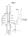
- Fig. 3 is a section of an NMR probe head according to the State of the art shown, in which the sample tube 6 radially in the direction heat currents Q are emitted onto the RF reception coil system 1 by radiation, since the receiving coil system 1 is at a cryogenic temperature of about 25 K while the sample tube 6 is held by means of the tempered air flow 8 supplied below approximately to room temperature to be held. Due to the heat radiation from the sample tube 6 arises taking into account the supply with the tempering current 8 Heat a temperature curve in the axial direction within the sample tube 6, as shown schematically on the right side of FIG. 3.
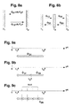
- transverse gradients can also be used occur when the sample tube 6 is not exactly in the middle of the Room temperature tube 4 is placed, as in Fig. 4a in a horizontal section shown schematically.
- the middle part 5 of the room temperature pipe 4 made of good heat-conducting material. This allows the transversal Temperature gradients (x-y direction) can be greatly reduced. It however, only materials are considered whose absorption for HF radiation is negligible and at the same time the required high thermal conductivity to have. Specifically, sapphire is a suitable material here.
- the radiation power between a surface F 1 at a temperature T 1 and an opposite surface F 2 at a temperature T 2 is shown schematically in FIG. 8a.
- a black radiation shield F 3 is now introduced between the two surfaces F 1 and F 2 , which stands without any direct thermal contact with the other two surfaces F 1 and F 2 , a temperature T 3 is established there as equilibrium due to the radiation fields , as indicated in Fig. 8b.
- Fig. 9c is only a generalization of the situation shown in Fig. 9b shown on N radiation shields, each in the implementation of the invention should be arranged radially one behind the other with respect to the z-axis.
- Figures 11a and 11b show a preferred embodiment of the invention NMR probe head with a centering device shown in Embodiment four spacers distributed symmetrically about the z-axis 10 includes. Thanks to the clean centering of the sample tube 6 within the room temperature tube 4 can, as already explained above, convection currents and thus the formation of temperature gradients can be avoided within the sample substance 7.
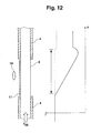
- Fig. 12 is a schematic vertical cross section of an inventive NMR probe head with a temperature control device 11 in the axial area the inner tube 5 of a room temperature tube 4 and the associated one Temperature curve shown along the z-axis.
- the temperature control device 11 can for example by an electric heater and / or by a Radiant heating of a corresponding surface on the room temperature pipe 4 can be realized in the area of the inner tube 5 with the aid of a heating device 19.
- the temperature curve along the z-axis shown on the right shows in the solid line the situation without tempering device and dashed the situation with a controlled temperature control device, where an almost constant temperature along the entire z-axis can be observed can.
Landscapes
- Physics & Mathematics (AREA)
- Condensed Matter Physics & Semiconductors (AREA)
- General Physics & Mathematics (AREA)
- Investigating Or Analyzing Materials Using Thermal Means (AREA)
- Magnetic Resonance Imaging Apparatus (AREA)
Applications Claiming Priority (2)
| Application Number | Priority Date | Filing Date | Title |
|---|---|---|---|
| DE10006317 | 2000-02-12 | ||
| DE10006317A DE10006317C1 (de) | 2000-02-12 | 2000-02-12 | Gekühlter NMR-Probenkopf mit thermischer Isolation der Meßprobe |
Publications (3)
| Publication Number | Publication Date |
|---|---|
| EP1124138A2 true EP1124138A2 (fr) | 2001-08-16 |
| EP1124138A3 EP1124138A3 (fr) | 2003-07-16 |
| EP1124138B1 EP1124138B1 (fr) | 2007-06-06 |
Family
ID=7630730
Family Applications (1)
| Application Number | Title | Priority Date | Filing Date |
|---|---|---|---|
| EP00127773A Expired - Lifetime EP1124138B1 (fr) | 2000-02-12 | 2000-12-19 | Tête RMN réfrigérée avec isolation thermique de l'échantillon |
Country Status (4)
| Country | Link |
|---|---|
| US (1) | US6441617B2 (fr) |
| EP (1) | EP1124138B1 (fr) |
| JP (3) | JP3573449B2 (fr) |
| DE (1) | DE10006317C1 (fr) |
Families Citing this family (41)
| Publication number | Priority date | Publication date | Assignee | Title |
|---|---|---|---|---|
| DE10111672C2 (de) * | 2001-03-09 | 2003-02-06 | Bruker Biospin Ag Faellanden | Vorrichtung zur genauen Zentrierung eines NMR-Probengläschens |
| GB0121603D0 (en) * | 2001-09-06 | 2001-10-24 | Oxford Instr Superconductivity | Magnet assembly |
| DE10157972B4 (de) * | 2001-11-27 | 2004-01-08 | Bruker Biospin Ag | NMR-Spektrometer und Betriebsverfahren mit Stabilisierung der transversalen Magnetisierung bei supraleitenden NMR-Resonatoren |
| US6768304B2 (en) * | 2002-02-22 | 2004-07-27 | Varian, Inc. | On-flow preheating in NMR measurements |
| DE10225958B3 (de) * | 2002-06-12 | 2004-03-04 | Bruker Biospin Ag | Vorrichtung zur Positionierung eines mit einer Messsubstanz gefüllten länglichen Probenröhrchens relativ zu einem NMR-Empfangsspulensystem |
| US6917201B2 (en) * | 2002-12-09 | 2005-07-12 | Varian, Inc. | Squashed liquid NMR sample tubes and RF coils |
| DE10340352B4 (de) * | 2003-09-02 | 2005-10-20 | Bruker Biospin Ag Faellanden | Kryokopf mit mehreren Wärmetauschern für die Kühlung der HF-Spulen oder Resonatoren |
| US6972568B2 (en) * | 2003-09-09 | 2005-12-06 | Varian, Inc. | Radially-compact NMR flow cell assemblies and methods |
| GB0403377D0 (en) * | 2004-02-16 | 2004-03-17 | Univ Aberdeen | Liquified gas cryostat |
| JP4319650B2 (ja) * | 2005-07-29 | 2009-08-26 | 株式会社日立製作所 | Nmr用低温プローブおよびnmr装置 |
| DE102005041383B4 (de) * | 2005-09-01 | 2007-09-27 | Bruker Biospin Ag | NMR-Apparatur mit gemeinsam gekühltem Probenkopf und Kryobehälter und Verfahren zum Betrieb derselben |
| WO2007049426A1 (fr) * | 2005-10-25 | 2007-05-03 | Hitachi, Ltd. | Sonde et appareil a resonance magnetique nucleaire |
| DE102006046888B4 (de) * | 2006-10-04 | 2010-12-16 | Bruker Biospin Ag | Gekühlter Magnet-Resonanz-Probenkopf mit einem Vakuumbehälter sowie zugehörige NMR-Messapparatur |
| JP5217057B2 (ja) * | 2008-06-30 | 2013-06-19 | 株式会社 Jeol Resonance | 高温測定用nmrプローブ |
| EP2453250B1 (fr) | 2009-06-30 | 2019-06-12 | Aspect Imaging Ltd. | Cage dans un appareil à résonance magnétique avec système de fixation/atténuation |
| AU2010273298B2 (en) | 2009-07-15 | 2014-10-23 | Viewray Technologies, Inc. | Method and apparatus for shielding a linear accelerator and a magnetic resonance imaging device from each other |
| US8461841B2 (en) | 2009-08-30 | 2013-06-11 | Aspect Imaging Ltd. | Means and method for thermoregulating magnets within magnetic resonance devices |
| US10076266B2 (en) | 2010-07-07 | 2018-09-18 | Aspect Imaging Ltd. | Devices and methods for a neonate incubator, capsule and cart |
| US11278461B2 (en) | 2010-07-07 | 2022-03-22 | Aspect Imaging Ltd. | Devices and methods for a neonate incubator, capsule and cart |
| FR2986609B1 (fr) * | 2012-02-07 | 2017-06-02 | Commissariat Energie Atomique | Dispositif d'isolation thermique et procede de fonctionnement d'un tel dispositif |
| JP6019515B2 (ja) * | 2012-05-15 | 2016-11-02 | 日本電子株式会社 | Nmr用試料管およびnmr装置 |
| US9927336B2 (en) | 2012-06-04 | 2018-03-27 | Cornell University | Apparatus and methods for low temperature small angle X-ray scattering |
| DE102012217601B4 (de) | 2012-09-27 | 2016-10-13 | Bruker Biospin Ag | NMR-Messanordnung mit Temperiereinrichtung für ein Probenröhrchen |
| GB2506851B (en) * | 2012-09-28 | 2014-11-12 | Schlumberger Holdings | NMR sample containment |
| US9889318B2 (en) | 2012-10-26 | 2018-02-13 | Viewray Technologies, Inc. | Assessment and improvement of treatment using imaging of physiological responses to radiation therapy |
| CA2910540C (fr) | 2013-05-03 | 2020-03-10 | Quantum Valley Investment Fund LP | Utilisation d'une cavite pour polariser un ensemble de spins |
| CN105474027A (zh) | 2013-05-03 | 2016-04-06 | 量子谷投资基金有限合伙公司 | 转移自旋极化 |
| GB2515524A (en) * | 2013-06-26 | 2014-12-31 | John Beausire Wyatt Webber | Nuclear magnetic resonance probes |
| DE102013215918B4 (de) * | 2013-08-12 | 2017-07-27 | Siemens Healthcare Gmbh | Thermostabilisierung einer Antennenanordnung für Magnetresonanztomographie |
| EP3423153B1 (fr) | 2016-03-02 | 2021-05-19 | ViewRay Technologies, Inc. | Thérapie par particules à imagerie par résonance magnétique |
| US11988730B2 (en) | 2016-08-08 | 2024-05-21 | Aspect Imaging Ltd. | Device, system and method for obtaining a magnetic measurement with permanent magnets |
| US10224135B2 (en) | 2016-08-08 | 2019-03-05 | Aspect Imaging Ltd. | Device, system and method for obtaining a magnetic measurement with permanent magnets |
| US11287497B2 (en) | 2016-08-08 | 2022-03-29 | Aspect Imaging Ltd. | Device, system and method for obtaining a magnetic measurement with permanent magnets |
| US10847294B2 (en) | 2017-07-10 | 2020-11-24 | Aspect Imaging Ltd. | System for generating a magnetic field |
| JP6783268B2 (ja) * | 2018-04-26 | 2020-11-11 | 日本電子株式会社 | Nmrプローブ |
| DE102019212508A1 (de) * | 2019-08-21 | 2021-02-25 | Bruker Switzerland Ag | Temperiersystem für MR-Geräte mit Permanentmagnetanordung |
| DE102020202243A1 (de) * | 2020-02-21 | 2021-08-26 | Bruker Switzerland Ag | Probenkopfseitige Probenverlängerung zur Reduktion der B0-Feldstörung des Probenröhrchenendes |
| CN111678938B (zh) * | 2020-07-17 | 2021-08-24 | 中南大学 | 一种多场耦合岩土核磁共振在线监测系统 |
| US12601798B2 (en) * | 2024-04-08 | 2026-04-14 | 4IR Solutions Ltd. | Nuclear magnetic resonance device |
| DE102024203915B3 (de) * | 2024-04-25 | 2025-07-17 | Bruker Switzerland Ag | NMR-Probenröhrchen mit variierendem Außendurchmesser, NMR-Probenkopf mit variierendem Innendurchmesser, NMR-Probenkopf-Anordnung mit Gasexpansionsdüse, Temperierverfahren |
| DE102025109424B3 (de) | 2025-03-12 | 2026-03-26 | Bruker Biospin Gmbh & Co. Kg | NMR-Probenkopf mit Temperiervorrichtung aus thermisch gut leitfähigem Material |
Family Cites Families (7)
| Publication number | Priority date | Publication date | Assignee | Title |
|---|---|---|---|---|
| US3764892A (en) * | 1971-01-04 | 1973-10-09 | Southwest Res Inst | Spectroscopic apparatus |
| US4587492A (en) * | 1984-03-02 | 1986-05-06 | Varian Associates, Inc. | Thermal barrier for variable temperature NMR |
| DE4013111C2 (de) * | 1990-04-25 | 1994-05-26 | Spectrospin Ag | HF-Empfangsspulenanordnung für NMR-Spektrometer |
| US5258710A (en) * | 1992-03-27 | 1993-11-02 | General Electric Company | Cryogenic probe for NMR microscopy |
| US5508613A (en) * | 1994-08-29 | 1996-04-16 | Conductus, Inc. | Apparatus for cooling NMR coils |
| EP0738897B1 (fr) * | 1995-03-25 | 2000-08-09 | Bruker AG | Dispositif de bobines de réception HF pour spectromètre RMN |
| EP0782005B1 (fr) * | 1995-12-20 | 2002-03-27 | Bruker AG | Tête d'échantillon pour un spectromètre RMN |
-
2000
- 2000-02-12 DE DE10006317A patent/DE10006317C1/de not_active Expired - Lifetime
- 2000-12-19 EP EP00127773A patent/EP1124138B1/fr not_active Expired - Lifetime
-
2001
- 2001-01-22 US US09/765,279 patent/US6441617B2/en not_active Expired - Lifetime
- 2001-02-09 JP JP2001034697A patent/JP3573449B2/ja not_active Expired - Lifetime
-
2004
- 2004-05-07 JP JP2004139122A patent/JP4027341B2/ja not_active Expired - Fee Related
- 2004-05-07 JP JP2004139121A patent/JP3990682B2/ja not_active Expired - Fee Related
Also Published As
| Publication number | Publication date |
|---|---|
| JP4027341B2 (ja) | 2007-12-26 |
| JP3990682B2 (ja) | 2007-10-17 |
| DE10006317C1 (de) | 2001-08-16 |
| US20010013779A1 (en) | 2001-08-16 |
| EP1124138A3 (fr) | 2003-07-16 |
| JP2001242230A (ja) | 2001-09-07 |
| JP2004226420A (ja) | 2004-08-12 |
| EP1124138B1 (fr) | 2007-06-06 |
| JP3573449B2 (ja) | 2004-10-06 |
| US6441617B2 (en) | 2002-08-27 |
| JP2004226421A (ja) | 2004-08-12 |
Similar Documents
| Publication | Publication Date | Title |
|---|---|---|
| EP1124138A2 (fr) | Tête RMN réfrigérée avec isolation thermique de l'échantillon | |
| EP1126284B1 (fr) | Tête support d'échantillon pour la RMN avec équilibrage uniforme de la température de l'échantillon | |
| EP1124137B1 (fr) | Tête refroidie de support d'échantillon pour RMN avec dispositif de centrage d'échantillon | |
| DE60225247T2 (de) | Sonde für ein NMR-Gerät, wobei Magnesiumdiborid verwendet wird | |
| DE69633417T2 (de) | Dünnfilmkondensator zur Verwendung mit einer Induktivität in einer Sondenspule für die kernmagnetische Resonanz | |
| DE19680973B4 (de) | Verwendung eines Probenrohrs in der NMR-Spektroskopie | |
| EP2269045B1 (fr) | Structure de double résonance et procédé pour l'étude d'échantillons à l'aide d'une dnp et/ou d'une endor | |
| EP0738897B1 (fr) | Dispositif de bobines de réception HF pour spectromètre RMN | |
| EP1909111B1 (fr) | Récipient sous vide pour tête d'échantillon à résonance magnétique refroidie | |
| DE19937566C2 (de) | Hochdruckpolarisator für Edelgase und Verfahren zum Betreiben des Polarisators | |
| EP0895092A1 (fr) | Résonateur hybride supraconducteur pour la réception de signaux RMN | |
| DE4408195C2 (de) | Resonator für die Kernspinresonanz | |
| DE112015000432T5 (de) | Einstellbarer Mikrowellenresonator für die statische dynamische Kernpolarisation | |
| DE60131386T2 (de) | Mehrschichtige NMR-Proben-RF-Spulen | |
| CH708630A2 (de) | DNP-Vorrichtung. | |
| EP2414820B1 (fr) | Structure à double résonance et procédé d'examen d'échantillons dotés de plusieurs rubans conducteurs | |
| DE1673268C3 (de) | Sonde für Resonanzspektrometer | |
| DE102007049701B4 (de) | NMR-Messkopf mit mehreren Resonatorsystemen zur simultanen Vermessung mehrerer Messproben in einem gekoppelten Mode | |
| DE112018000097T5 (de) | Gepulstes Elektronen-Paramagnetresonanzspektrometer | |
| DE102022212952B4 (de) | Dnp-probenkopf für hochauflösende flüssigkeits-nmr | |
| DE3011479A1 (de) | Magnetisches kernresonanzspektrometer | |
| DE102012222253A1 (de) | Magnetische kernresonanzsonde mit infrarot-reflexionsflächen | |
| DE1523101B2 (de) | Mikrowellen-hohlraumresonator | |
| DE102025109424B3 (de) | NMR-Probenkopf mit Temperiervorrichtung aus thermisch gut leitfähigem Material | |
| DE1523101C3 (de) | MikroweUen-Hohlraumresonator |
Legal Events
| Date | Code | Title | Description |
|---|---|---|---|
| PUAI | Public reference made under article 153(3) epc to a published international application that has entered the european phase |
Free format text: ORIGINAL CODE: 0009012 |
|
| AK | Designated contracting states |
Kind code of ref document: A2 Designated state(s): AT BE CH CY DE DK ES FI FR GB GR IE IT LI LU MC NL PT SE TR |
|
| AX | Request for extension of the european patent |
Free format text: AL;LT;LV;MK;RO;SI |
|
| RAP1 | Party data changed (applicant data changed or rights of an application transferred) |
Owner name: BRUKER BIOSPIN AG |
|
| PUAL | Search report despatched |
Free format text: ORIGINAL CODE: 0009013 |
|
| RIC1 | Information provided on ipc code assigned before grant |
Ipc: 7G 01R 33/31 B Ipc: 7G 01R 33/30 A |
|
| AK | Designated contracting states |
Designated state(s): AT BE CH CY DE DK ES FI FR GB GR IE IT LI LU MC NL PT SE TR |
|
| AX | Request for extension of the european patent |
Extension state: AL LT LV MK RO SI |
|
| 17P | Request for examination filed |
Effective date: 20030918 |
|
| AKX | Designation fees paid |
Designated state(s): CH DE FR GB LI |
|
| RBV | Designated contracting states (corrected) |
Designated state(s): CH DE FR GB LI |
|
| RTI1 | Title (correction) |
Free format text: COOLED NMR PROBE HEAD WITH THERMAL ISOLATION OF THE SAMPLE TO BE MEASURED |
|
| GRAP | Despatch of communication of intention to grant a patent |
Free format text: ORIGINAL CODE: EPIDOSNIGR1 |
|
| RBV | Designated contracting states (corrected) |
Designated state(s): CH FR GB LI |
|
| GRAS | Grant fee paid |
Free format text: ORIGINAL CODE: EPIDOSNIGR3 |
|
| REG | Reference to a national code |
Ref country code: DE Ref legal event code: 8566 |
|
| GRAA | (expected) grant |
Free format text: ORIGINAL CODE: 0009210 |
|
| AK | Designated contracting states |
Kind code of ref document: B1 Designated state(s): CH FR GB LI |
|
| REG | Reference to a national code |
Ref country code: GB Ref legal event code: FG4D Free format text: NOT ENGLISH |
|
| REG | Reference to a national code |
Ref country code: CH Ref legal event code: EP |
|
| GBT | Gb: translation of ep patent filed (gb section 77(6)(a)/1977) |
Effective date: 20070720 |
|
| ET | Fr: translation filed | ||
| PLBE | No opposition filed within time limit |
Free format text: ORIGINAL CODE: 0009261 |
|
| STAA | Information on the status of an ep patent application or granted ep patent |
Free format text: STATUS: NO OPPOSITION FILED WITHIN TIME LIMIT |
|
| 26N | No opposition filed |
Effective date: 20080307 |
|
| REG | Reference to a national code |
Ref country code: FR Ref legal event code: PLFP Year of fee payment: 16 |
|
| REG | Reference to a national code |
Ref country code: FR Ref legal event code: PLFP Year of fee payment: 17 |
|
| PGFP | Annual fee paid to national office [announced via postgrant information from national office to epo] |
Ref country code: CH Payment date: 20161222 Year of fee payment: 17 Ref country code: GB Payment date: 20161222 Year of fee payment: 17 |
|
| PGFP | Annual fee paid to national office [announced via postgrant information from national office to epo] |
Ref country code: FR Payment date: 20161221 Year of fee payment: 17 |
|
| REG | Reference to a national code |
Ref country code: CH Ref legal event code: PL |
|
| GBPC | Gb: european patent ceased through non-payment of renewal fee |
Effective date: 20171219 |
|
| REG | Reference to a national code |
Ref country code: FR Ref legal event code: ST Effective date: 20180831 |
|
| PG25 | Lapsed in a contracting state [announced via postgrant information from national office to epo] |
Ref country code: FR Free format text: LAPSE BECAUSE OF NON-PAYMENT OF DUE FEES Effective date: 20180102 |
|
| PG25 | Lapsed in a contracting state [announced via postgrant information from national office to epo] |
Ref country code: GB Free format text: LAPSE BECAUSE OF NON-PAYMENT OF DUE FEES Effective date: 20171219 Ref country code: LI Free format text: LAPSE BECAUSE OF NON-PAYMENT OF DUE FEES Effective date: 20171231 Ref country code: CH Free format text: LAPSE BECAUSE OF NON-PAYMENT OF DUE FEES Effective date: 20171231 |