EP1124147A2 - Optischer Koppler mit optischem Stecker und Kreuzverbindungsverfahren - Google Patents
Optischer Koppler mit optischem Stecker und Kreuzverbindungsverfahren Download PDFInfo
- Publication number
- EP1124147A2 EP1124147A2 EP01300729A EP01300729A EP1124147A2 EP 1124147 A2 EP1124147 A2 EP 1124147A2 EP 01300729 A EP01300729 A EP 01300729A EP 01300729 A EP01300729 A EP 01300729A EP 1124147 A2 EP1124147 A2 EP 1124147A2
- Authority
- EP
- European Patent Office
- Prior art keywords
- fiber optic
- optical
- cables
- fiber
- plane
- Prior art date
- Legal status (The legal status is an assumption and is not a legal conclusion. Google has not performed a legal analysis and makes no representation as to the accuracy of the status listed.)
- Withdrawn
Links
Images



Classifications
-
- G—PHYSICS
- G02—OPTICS
- G02B—OPTICAL ELEMENTS, SYSTEMS OR APPARATUS
- G02B6/00—Light guides; Structural details of arrangements comprising light guides and other optical elements, e.g. couplings
- G02B6/44—Mechanical structures for providing tensile strength and external protection for fibres, e.g. optical transmission cables
- G02B6/4439—Auxiliary devices
- G02B6/4471—Terminating devices ; Cable clamps
- G02B6/4472—Manifolds
-
- G—PHYSICS
- G02—OPTICS
- G02B—OPTICAL ELEMENTS, SYSTEMS OR APPARATUS
- G02B6/00—Light guides; Structural details of arrangements comprising light guides and other optical elements, e.g. couplings
- G02B6/24—Coupling light guides
- G02B6/36—Mechanical coupling means
- G02B6/3608—Fibre wiring boards, i.e. where fibres are embedded or attached in a pattern on or to a substrate, e.g. flexible sheets
-
- G—PHYSICS
- G02—OPTICS
- G02B—OPTICAL ELEMENTS, SYSTEMS OR APPARATUS
- G02B6/00—Light guides; Structural details of arrangements comprising light guides and other optical elements, e.g. couplings
- G02B6/24—Coupling light guides
- G02B6/36—Mechanical coupling means
- G02B6/38—Mechanical coupling means having fibre to fibre mating means
- G02B6/3807—Dismountable connectors, i.e. comprising plugs
- G02B6/3833—Details of mounting fibres in ferrules; Assembly methods; Manufacture
- G02B6/3834—Means for centering or aligning the light guide within the ferrule
- G02B6/3838—Means for centering or aligning the light guide within the ferrule using grooves for light guides
- G02B6/3839—Means for centering or aligning the light guide within the ferrule using grooves for light guides for a plurality of light guides
-
- G—PHYSICS
- G02—OPTICS
- G02B—OPTICAL ELEMENTS, SYSTEMS OR APPARATUS
- G02B6/00—Light guides; Structural details of arrangements comprising light guides and other optical elements, e.g. couplings
- G02B6/24—Coupling light guides
- G02B6/36—Mechanical coupling means
- G02B6/38—Mechanical coupling means having fibre to fibre mating means
- G02B6/3807—Dismountable connectors, i.e. comprising plugs
- G02B6/3873—Connectors using guide surfaces for aligning ferrule ends, e.g. tubes, sleeves, V-grooves, rods, pins, balls
- G02B6/3874—Connectors using guide surfaces for aligning ferrule ends, e.g. tubes, sleeves, V-grooves, rods, pins, balls using tubes, sleeves to align ferrules
- G02B6/3878—Connectors using guide surfaces for aligning ferrule ends, e.g. tubes, sleeves, V-grooves, rods, pins, balls using tubes, sleeves to align ferrules comprising a plurality of ferrules, branching and break-out means
- G02B6/3879—Linking of individual connector plugs to an overconnector, e.g. using clamps, clips, common housings comprising several individual connector plugs
-
- G—PHYSICS
- G02—OPTICS
- G02B—OPTICAL ELEMENTS, SYSTEMS OR APPARATUS
- G02B6/00—Light guides; Structural details of arrangements comprising light guides and other optical elements, e.g. couplings
- G02B6/24—Coupling light guides
- G02B6/36—Mechanical coupling means
- G02B6/38—Mechanical coupling means having fibre to fibre mating means
- G02B6/3807—Dismountable connectors, i.e. comprising plugs
- G02B6/3873—Connectors using guide surfaces for aligning ferrule ends, e.g. tubes, sleeves, V-grooves, rods, pins, balls
- G02B6/3885—Multicore or multichannel optical connectors, i.e. one single ferrule containing more than one fibre, e.g. ribbon type
-
- G—PHYSICS
- G02—OPTICS
- G02B—OPTICAL ELEMENTS, SYSTEMS OR APPARATUS
- G02B6/00—Light guides; Structural details of arrangements comprising light guides and other optical elements, e.g. couplings
- G02B6/24—Coupling light guides
- G02B6/36—Mechanical coupling means
- G02B6/3628—Mechanical coupling means for mounting fibres to supporting carriers
- G02B6/3648—Supporting carriers of a microbench type, i.e. with micromachined additional mechanical structures
- G02B6/3652—Supporting carriers of a microbench type, i.e. with micromachined additional mechanical structures the additional structures being prepositioning mounting areas, allowing only movement in one dimension, e.g. grooves, trenches or vias in the microbench surface, i.e. self aligning supporting carriers
-
- G—PHYSICS
- G02—OPTICS
- G02B—OPTICAL ELEMENTS, SYSTEMS OR APPARATUS
- G02B6/00—Light guides; Structural details of arrangements comprising light guides and other optical elements, e.g. couplings
- G02B6/24—Coupling light guides
- G02B6/36—Mechanical coupling means
- G02B6/3628—Mechanical coupling means for mounting fibres to supporting carriers
- G02B6/3664—2D cross sectional arrangements of the fibres
- G02B6/3668—2D cross sectional arrangements of the fibres with conversion in geometry of the cross section
-
- G—PHYSICS
- G02—OPTICS
- G02B—OPTICAL ELEMENTS, SYSTEMS OR APPARATUS
- G02B6/00—Light guides; Structural details of arrangements comprising light guides and other optical elements, e.g. couplings
- G02B6/24—Coupling light guides
- G02B6/36—Mechanical coupling means
- G02B6/3628—Mechanical coupling means for mounting fibres to supporting carriers
- G02B6/3664—2D cross sectional arrangements of the fibres
- G02B6/3676—Stacked arrangement
-
- G—PHYSICS
- G02—OPTICS
- G02B—OPTICAL ELEMENTS, SYSTEMS OR APPARATUS
- G02B6/00—Light guides; Structural details of arrangements comprising light guides and other optical elements, e.g. couplings
- G02B6/24—Coupling light guides
- G02B6/36—Mechanical coupling means
- G02B6/3628—Mechanical coupling means for mounting fibres to supporting carriers
- G02B6/3684—Mechanical coupling means for mounting fibres to supporting carriers characterised by the manufacturing process of surface profiling of the supporting carrier
- G02B6/3696—Mechanical coupling means for mounting fibres to supporting carriers characterised by the manufacturing process of surface profiling of the supporting carrier by moulding, e.g. injection moulding, casting, embossing, stamping, stenciling, printing, or with metallic mould insert manufacturing using LIGA or MIGA techniques
Definitions
- optical fibers are very popular medium for large bandwidth communication applications.
- optical technology is being utilized more and more in broadband systems wherein communications between systems take place on high-speed optical channels.
- the need for efficient utilization of the precious real estate on circuit boards, racks/shelves, back planes, distribution cabinets, etc. is becoming ever increasingly important.
- opto-electronic modules and optic fiber devices need to continue to be made miniaturized or compact, thereby taking full advantage of the maturity of micro-and opto-electronic technologies for generating, transporting, managing and delivering broadband services to ever increasing bandwidth demands of end users at increasingly lower costs.
- the industry has placed an emphasis on small optical connectors and optical harnesses, both simple and complex.
- miniaturizing and compacting is tempered by the requirements of transmission efficiency and organization.
- multi-fiber ribbon in which a plurality of optical fibers are organized and contained side by side in a plastic ribbon. It is known to interconnect these ribbon cables by supporting the fibers between two support members made of a monocrystaline material, such as silicon. In the support members are V-grooves formed utilizing photolithographic masking and etching techniques.
- the fibers are placed side by side in individual V-grooves of one support member and the other mating support member having corresponding V-grooves is placed over the fibers so as to bind or hold the fibers in a high precision spatial relationship between the mating V-grooves.
- the top and bottom support members sandwiching the multi-fiber ribbon are typically bonded together with a clamp or adhesive, forming a plug of a multi-fiber connector.
- Two mating plugs with the same fiber spacing may then be placed in an abutting relationship so that the ends of the fibers of the respective plugs are substantially co-axially aligned with one another, thereby forming a multi-fiber connection. If desired, such plugs can be stacked in order to increase the interconnection density.
- Multi-fiber ribbons and connectors have numerous applications in optic communication systems. For instance, optical switches, optical power splitters/combiners, routers, etc., have several input and/or output ports arranged as linear arrays to which a plurality of fibers are to be coupled. Further, since optical fibers are attached somehow to launch optical signals into these devices and extract optical signals therefrom, splicing of arrays of fibers (i.e., a multi-fiber ribbon) to such devices can be achieved using multi-fiber connectors. Another possible application relates to an optical fan-out fabric where an array of fibers in a multi-fiber ribbon may be broken into simplex or duplex channels for distribution purposes, as is often desired.
- each of the multiple input ports typically comprising more than one optical fiber
- each of the multiple output ports which also typically comprises more than one optical fiber.
- the perfect shuffle cross-connect provides for multi-channel optical transmissions, for example as in multi-wavelength transmissions, to be mixed in an orderly fashion.
- Such connections are made by flexible optical circuits or complex jumpers. While complex jumpers take up space and create congestion, the flexible optical circuit is expensive to produce, often requiring highly skilled labor, such as a CAD designer to generate the original drawings of the circuit, and expensive processing machines such as those for fiber routing, lamination and connectorization equipment.
- connection system should be capable of being manufactured and assembled easily and inexpensively.
- the present invention is an optical harness for an optical cross-connect defined primarily by a first portion and a second portion.
- the first portion of the optical harness comprises a number M of fiber optic row cables where each fiber optic row cable comprises an array of a number N of fibers arranged on a first plane.
- the first plane on which each fiber optic row cable is disposed is substantially parallel to each other first plane on which a fiber optic row cable is disposed.
- the second portion of the optical harness comprises a number N of fiber optic column cables where each fiber optic column cable comprises an array of a number M of fibers arranged on a second plane angularly disposed relative to the first plane.
- the second plane on which each fiber optic column cable is disposed is substantially parallel to each other second plane on which a fiber optic column cable is disposed.
- the optical harness further comprises a holding mechanism disposed intermediate the first portion and the second portion of the optical harness.
- the orientation of the first planes on which the fiber optic row cables are disposed is arranged at a defined angle relative to the second planes on which the fiber optic column cables are disposed.
- the holding mechanism is arranged and configured to transition the fibers from one configuration toward the first portion to the other configuration toward the second portion and to maintain the relative angled arrangement.
- the present invention can also be viewed as a method for providing an optical cross-connect between a first element and a second element between which distribution or re-routing accurately positioned optical fibers in predetermined configuration is desired.
- the method can be broadly summarized by the following steps: providing a number M of fiber optic row cables having a defined length, where each fiber optic row cable comprises an array of a number N of fibers arranged on a first plane substantially parallel to the first plane of each of the other fiber optic row cables; stacking the number M of fiber optic row cables; disposing a holding mechanism intermediate the defined length of the fiber optic row cables; separating each array of N fibers into individual fibers; re-grouping the fiber optics into a number N of fiber optic column cables, each comprising a number M of fibers; connecting the first portion of the cross-connect to the first element; and connecting the second portion of the cross-connect to the second element.
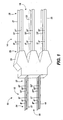
- FIG. 1 illustrates a perspective view of the present invention.
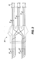
- FIG. 2 illustrates a perspective view showing a cut-away view of the holding mechanism of the optical harness of FIG. 1.
- FIG 3 is a perspective view of a plug-like optical connector, which is in the form of a stack of multi-fiber connectors terminating several optical fiber ribbons, in accordance with an embodiment of the present invention.
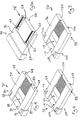
- FIG. 4 is an isolated perspective view of an inside surface of an outer support member of the stack of multi-fiber connectors of FIG. 3.
- FIG. 5A is an isolated perspective views of an outside surface of the outer support member of FIG 4.
- FIG 5B is an isolated end elevation view of the outer support member of FIG. 4.
- FIG. 6 is an isolated perspective view of a first surface of an inner support member of the stack of multi-fiber connectors of FIG. 3.
- FIG. 7 is an isolated perspective view of a second surface of the inner support member of FIG. 6.
- FIG. 8 is an isolated perspective view of an alignment receptacle in accordance with the first embodiment of the present invention.
- FIG. 9 is a perspective view of a receptacle-like optical connector, which is in the form of the plug-like optical connector of FIG. 3 mated to the alignment receptacle of FIG. 8, in accordance with an embodiment of the present invention.
- FIG. 10 is a schematic top plan view of the plug-like optical connector of FIG. 3 mated to the receptacle-like optical connector of FIG. 9, in accordance with the first embodiment of the present invention.
- FIG. 11 is a perspective view of a plug-like optical connector, whic is in the form of a stack of multi-fiber connectors, in accordance with a second embodiment of the present invention.
- FIG. 12 is an isolated perspective view of an outside surface of an outer support member of the stack of multi-fiber connectors of FIG. 11.
- FIG. 13 is an isolated perspective view of an inside surface of the outer support member of FIG, 12.
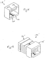
- FIG. 14 is an isolated perspective view of an alignment receptacle in accordance with another embodiment of the connector of the present invention.
- FIG. 15 is a perspective view of a receptacle-like optical connector, which is in the form of the plug-like optical connector of FIG. 11 mated to the alignment reseptacle of FIG. 14, in accordance with another embodiment of the connector of the present invention.
- Fig. I illustrates a preferred embodiment of an optical harness of the present invention, referred to generally as reference numeral 10.
- the optical harness 10 of the present invention provides an optical cross-connect capable of receiving multiple wavelengths and separating or mixing the wavelengths with accurately positioned optical fibers in a pre-designed configuration.
- the optical harness 10 transitions rows of a plurality of fibers 17, 19, disposed toward a first portion 12 of the optical harness 10, to a plurality of columns of fibers 21, 23, 25, disposed toward a second portion 14 of the harness 10, where the fibers have common positions in the rows.
- the present invention For receiving and re-routing M number of wavelengths, generally, the present invention embodies an optical harness 10 having a number M of fiber optic row cables 16 disposed toward a first portion 12 of an optical harness 10 and a number N of fiber optic column cables 18 disposed toward a second portion 14 of an optical harness 10.
- Each of the M number of fiber optic row cables 16 comprises an array comprising a number N of fiber optics arranged on a first plane that is substantially parallel to the first plane of each of the other M number of fiber optic row cables 16. It is preferable that each of the fiber optic row cables 16 is ribbonized, such as the type taught in U.S. Patent 4,900,126, the disclosure of which is herein incorporated by reference.
- Each of the N number of fiber optics is separated from its ribbonized configuration, re-routed, and configured such that each of the number N of fiber optic column cables 18 comprises an array of a number M of fibers.
- Each of the number M of fibers are arranged on a second plane substantially parallel to the second planes on which each of the other number N of fiber optic column cables 18 are arranged.
- each fiber optic in the array of the N number of fiber optics comprising each fiber optic row cable is re-routed to a different cable of the N number of fiber optic column cables.
- a holding and routing mechanism 20 is disposed intermediate first portion 12 and second portion 14 of the optical harness 10 and arranged and configured to maintain the fiber optic row cables 16 in the preferred first plane orientation and the fiber optic column cables 18 in the preferred second plane orientation.
- the optical fibers of the fiber optic column cables 18 can then be re-ribbonized in their new configuration.
- To provide a perfect shuffle cross-connect the fiber optics are re-routed in an organized manner.
- the optical fibers in a first position in each of the fiber optic row cables 16 can be re-routed to a first fiber optic column cable 18 and arranged "in order" such that the fiber re-routed from the first position fiber optic row cable is positioned as the first position fiber optic in the first position fiber optic column cable and the fiber optic re-routed from the second position fiber optic row cable is positioned as the second position fiber optic in the first position fiber optic column cable, and so on.
- the fibers can be coded, or marked, such as with color or by any other suitable means, to indicate their location in each fiber optic row cable (the fiber optic's position in an array). The fibers can be further marked to indicate from which fiber optic row cable 16 the fiber optic originated.
- the first position fiber optic row cable 17 comprises an array of fibers disposed in a first position fiber 31', preferably colored and marked, a second position fiber 32', preferably colored and marked, such as red R', and a third position fiber 33', preferably colored and marked, such as green G', arranged on a first plane.
- the second position fiber optic row cable 19 comprises a first position fiber 31'', preferably colored and marked, such as blue B", a second position fiber 32", preferably colored and marked, such as red R", and a third position fiber 33", preferably colored and marked G", arranged preferably on a first plane.
- the present invention can include any number of fiber optic row cables each comprising any number of fibers.
- the first position fiber optic row cable 17 and second position fiber optic row cable 19 are preferably ribbonized and collected by a holding mechanism 20. It is preferable that the first plane of the first fiber optic row cable 17 and the first plane of the second fiber optic row cable 19 are substantially parallel to each other. In this stacked configuration, the fibers are arranged in columns of like colors.
- the fiber optics comprising the fiber optic row cables are separated from their respective originating fiber optic row cables 17, 19, and re-grouped and preferably re-ribbonized, into columns of like colors.
- the columns of like colors comprise the fiber optic column cables disposed toward the second portion 14 of the optical harness 10.
- the holding mechanism 20 holds the stack of fiber optic row cables in position and prevents the point of separation of the fibers out of the fiber optic row cable configuration from traveling further along the fiber optic row cables.
- the re-configured fiber optics extend from the holding mechanism 20 grouped in a first position fiber optic column cable 21, a second position fiber optic column cable 23 and a third position fiber optic column cable 25.
- the first position fiber optic column cable 21 preferably comprises the first position fiber optic 31', preferably colored and marked, such as in blue B', (from the first position fiber optic row cable 17) and the first position fiber optic 31'', preferably colored and marked, such as in blue B", (from the second position fiber optic row cable 19), arranged on a second plane.
- the second position fiber optic column cable 23 comprises the second position fiber optic 32', preferably colored and marked, such as in red R', (from the first position fiber optic row cable 17) and the second position fiber optic 32'', preferably colored and marked, such as in red R", (from the second position fiber optic row cable 19), arranged on a second plane.
- the third position fiber optic column cable 25 comprises the third position fiber optic 33', preferably colored and marked, such as in green G', (from the first position fiber optic row cable 17) and the third position fiber optic 33", preferably colored and marked, such as in green G' ', (from the second position fiber optic row cable 19), arranged on a second plane.
- the first position for each of the fiber optic column cables originate from the first position fiber optic row cable 17.
- the second position fiber optics 31", 32" and 33", marked B", R'', and G", respectively are in the second position of each of the fiber optic column cables.
- each fiber optic row cable 17, 19 is in communication with each fiber optic column cable 21, 23, 25 by one fiber optic.
- This method of reconfiguration provides for the perfect shuffle cross-connect.
- marking each fiber optic to indicate its location at the first portion 12 of the optical harness 10 can assist in such an organized re-routing.
- Each of the fiber optic row cables 17, 19 are preferably arranged and held by the holding mechanism 20 on a first plane, each first plane being substantially parallel to the others.
- each of the fiber optic column cables 21, 23, 25 are preferably arranged and held by the holding mechanism 20 on a second plane, each second plane being substantially parallel to the others.
- the first planes on which the fiber optic row cables are arranged are preferably oriented at a defined angle relative to the second planes on which the fiber optic column cables are arranged. The defined angle can be substantially ninety degrees.
- opposing free ends of the fiber optic row cables and fiber optic column cables can further include connectors 42
- connectors 42 any connector capable of providing the desired communication can be used
- one preferred connecto r42 is a plug-like high-density optical connector 50 formed from stackable multi-fiber connectors. FIGS. 3-15 illustrate this preferred connector.
- FIG. 3 illustrate the preferred plug-lie optical connector 50 as desceived in U.S. Patent Application having the serial number 09/416,185, filed on October 11, 1999, which is herein fully incorporated by reference.
- the optical connector 50 includes opposite right and left sides 52, 54 that extend vertically and in a longitudinal direction.
- the optical connector 50 further includes opposite top and bottom sides 56, 58 that extend in the longitudinal direction and horizontally between the right and left sides 52, 54.
- An optical end face 60 extends generally perpendicular to the longitudinal direction and between forward edges of the right, left, top and bottom sides 52, 54, 56, 58. More specifically, the optical end face 60 includes right, left, top, and bottom edges that are respectively contiguous with the forward edges of the right, left, top, and bottom sides 52, 54, 56, 58.
- plug-like optical connector items are described in the context of specific orientations, such as horizontal and vertical orientations. Those orientations are intended to provide a frame of reference to aid in the explanation of the present invention.
- the connector of the present invention can be described in the context of other orientations and is not limited to any specific orientation.
- the optical connector 50 includes a pair of upper alignment members and a pair of lower alignment members that are operative, as will be discussed in greater detail below, for aligning the optical end face 60 of the optical connector with an optical end face of another optical connector.
- the alignment members may be dowels or pins, or the like, associated with a first connector, and correspondingly shaped apertures, or the like, associated with a second connector that is capable of mating with the first connector.
- the pair of upper alignment members includes a pair of alignment surfaces 62 are located at the top side 56 of the optical connector 50 and define a pair of alignment grooves 64 that extend in the longitudinal direction along the top side of the optical connector 50.
- the pair of lower alignment members includes a pair of alignment surfaces 62 that are located on the bottom side 58 of the optical connector 50 and define a pair of alignment grooves 64 that extend in the longitudinal direction along the bottom side of the optical connector 50.
- the alignment grooves 64 at the top side 56 are open at the optical end face 60 as well as along the top side.
- the alignment grooves 64 at the bottom side 58 are open at the optical end face 60 as well as long the bottom side 58.
- the alignment grooves 64 are in the form of truncated V-shapes.
- optical terminuses of the arrays 66 extend horizontally along the optical end face 60. It is within the scope of the connector of the present invention for the optical terminuses of the arrays 66 to be a variety of different types of optical devices. Examples of optical terminuses that are within the scope of the present invention include, but are not limited to, terminuses of optical fibers, optical transmitters, and optical receivers. Optical transmitters can be light emitting diodes, VCSELS, or the like. Optical receivers can be photoelectric cells, or the like. In accordance with this embodiment, in each array 66, a distance is defined between adjacent optical terminuses, and that distance is less than the distance defined between adjacent array.
- the optical connector 50 is stack of multi-fiber connectors and the optical terminuses of the array 66 are the terminuses of optical fibers ribbons 68.
- Optical fiber ribbons 68 illustrated in FIG. 3 can comprise either the fiber optic row cables 16, the fiber optic column cables 18, or fiber ribbons to which ribbons comprising the harness 10 can be connected as disclosed herein.
- the connector illustrated herein comprises optical terminuses for four optical fiber ribbons 68
- the connector of the present invention can comprise optical terminuses for any number of fiber ribbon 68
- the connector of the present invention can comprise optical terminuses for any number of fiber ribbons.
- each optical fiber ribbons 68 to be used with this preferred connector extends longitudinally and includes a lateral array of conventional coasted optical fibers that transmit light. It is preferred that optical fiber ribbon 68 further includes a solidified bonding material that fills the interstices between the optical fibers, binds together the optical fibers, and extends to the outside boundary of the optical fiber ribbon 68.
- the optical connector 50 may include two identical outer support members 70 that sandwich three identical inner support members 72.
- the connector 50 is shown as terminating four optical fiber ribbons 68. It will be apparent to those skilled in the art that the disclosed connector design may be utilized to terminate any number of optical fiber ribbons 68 and/or any number of optical fibers per optical fiber ribbon.
- the support members 70, 72 include paralled V-grooves that hold the optical fibers of the respective optical fiber ribbons 68 in precise, spaced alignment with respect to one another as the V-grooves of adjacent support members are laid over one another in a mating relationship.
- the terminuses of the individual optical fibers of the optical fiber ribbons 68 are substantially flush to the optical end face 60 of the optical connector 50 so that the optical fibers may be optically coupled to another connector or device, such as optical transmitter and receiver modules.
- an inside surface 74 and an outside surface 76 of a representative outer support member 70 are incldues a front portion 78 and a rear portion 80.
- an array of parallel V-grooves 82 for receiving and holding the optical fibers of an optical fiber ribbons 68 (FIG. 3) in precise alignment with respect to one another are provided in the front portion 78 of the inside surface 74.
- twelve V-grooves provided by the outer support member 70 it will be appreciated by those of ordinary skill in the art that more or fewer than twelve may be utilized. However, the maximum number may be limited by the physical size of the connector footprint.
- the outside surface 76 includes a pair of relatively large alignment grooves 64 (also see FIG. 3), which are laterally displaced from one another and are sized and shaped for holding alignment ridges, which are discussed below in detail.
- the alignment grooves 64 extend from the front portion 78 toward the rear portion 80 and terminate at a shoulder 86, the alignment grooves can be sized to extend from the front portion 78 to the opposite rear edge of the outside surface 76.
- the alignment grooves 64 are substantially larger than the individual grooves of the array of parallel V-grooves 64 are substantially larger than the individual grooves of the array of parallel V-grooves 82. More specifically, each of the alignment grooves 64 has a width "W1" and a height "H1" that are respectively at least twice as large as a corresponding width "W2" and height "H2" of each of the individual grooves of the array of parallel V-grooves 82.
- each the alignment grooves 64 has a width W1 of approximately 850 microns and a height H2 of approximately 375 to 400 microns
- each of the individual grooves of the array of parallel V-grooves 82 has a width W2 of approximately 150 microns and a height H1 of approximately 80 to 90 microns.
- the alignment grooves are substantially larger in diameter than the diameter of the optical fibers received by the V-grooves 82.
- each of the optical fibers can include a glass center that is surrounded by a coating, and the outer diameter of the coating is approximately 250 microns.
- the coating is stripped from the glass center and the glass center only is placed in the respective V-grooves 82.
- Each glass center has a diameter of approximately 125 microns.
- the r alignment grooves 64 are relatively large so that they are relatively strong, and relatively easy to manufacture and use.
- adjacent alignment grooves 64 are further apart than adjacent grooves of the array of parallel V-grooves 82, which further promotes ease of use.
- the rear portion 80 includes a ribbon recess 86 that holds an optical fiber ribbon 68 (FIG. 3) at approximately the point at which the individual optical fibers of the ribbon are separated and stripped.
- the ribbon recess 86 also provides space for the adhesive utilized to bond adjacent support members together, as discussed below.
- the ribbon recess 86 includes a strain relief element recess 88 for receiving and engaging a lip or other retaining structure at the end of an external strain relief element (not shown) associated with the optical fiber ribbon 68.
- a retaining pin 90 and a retaining slot 92 are provided on either side of the ribbon recess 86 for aligning and holding adjacent support members.
- the retaining pin 90 and slot 92 provide for the lateral alignment of adjacent support members so that corresponding arrays of V-grooves align with on another.
- the mating V-grooves can be fabricated with such precision, as discussed hereinafter, that the V-grooves themselves precisely align the individual optical fibers. This is inherent in the V-shaped design, which has an acceptance region for receiving an individual optical fiber.
- the optical fiber is held in a precise predetermined alignment by the sides of the V-grooves.
- the precise alignment of adjacent support members ensures that the mating V-grooves of adjacent support members are in registration with one another.
- the inner support member 72 includes a front portion 98 and a rear portion 100.
- a first array of parallel fiber-receiving V-grooves 102 are provided in the surface 94 at the front portion 98 for receiving and holding optical fibers of an optical fiber ribbon 68 (FIG. 3).
- the surface 96 of the inner support member 72 includes a second array of parallel fiber receiving V-grooves 102, 104 on opposite surfaces for mating with corresponding arrays of V-grooves formed in adjacent support members.
- the arrays of V-grooves 102, 104 are sized like the array of V-grooves 82 (FIGS. 4 and 5A).
- Retaining pins 106, 108 and retaining slots 110, 112 are provided on the surfaces 94, 96 at the rear portion 100 of the inner support member 72 for aligning and holding adjacent support members, as discussed above with respect to the outer support member 70 (FIGS. 3-SA).
- a ribbon recess 114 and a strain relief element recess 116 are provided in both surfaces 94, 96, al also discussed above with respect to the outer support member 70.
- the inner support member 72 does not include alignment grooves 64 (FIGS. 3-5B), or the like.
- the inside surfaces 74 of the outer support members 790 do not include alignment grooves 64, or the like. Accordingly, as best seen in FIGS. 4, 6 and 7, ample lateral space is available for the illustrate V-grooves 82, 102, 104, and sufficient free lateral space is available for enabling the further increase of interconnection density.
- the thickness of the inner support members 72 may be less than that of conventional support members since the inner support members 72, do not have to be thick enough to accommodate alignment grooves, or the like. Accordingly, by reducing the thickness of the inner support members 72, a stackable multi-fiber connector can be made small enough-to be received within a smaller connector housing, thereby enable a further increase of interconnection density.
- the optical connector 50 may terminate any number of optical fiber ribbons 68 by utilizing two outer support members 70 and an appropriate number of inner support members 72.
- the overall costs of stackable multi-fiber connector in accordance with the present invention can be less than that of comparable stackable connectors that require more than two types of components.
- the support members can be fabricated using plastic injection molding techniques with only two molds: one for the outer support member 70 and one for the inner support member 72. This further increases the precision of the V-grooves because adjacent parts may be formed from the same mold.
- the support member 70, 72 are preferably fabricated using the techniques described in U.S. Patent Nos. 5,388,174; 5,620,634 and 5,603,870, each of which is incorporated herein by reference. This process has been proven to consistently and reliably produce features with accuracy on the order of 1 ⁇ m or better. Generally, and example of this process is as follows. Initially, a monocrystalline body, such as a silicon chip, is anisotropically etched using conventional masking and etching techniques to produce grooves corresponding to grooves selected from the V-grooves 82, 102, 104 (FIGS. SA, 6, 7) and alignment grooves 64 (FIGS. 3-SB).
- a monocrystalline body such as a silicon chip
- etch rate of the silicon may be several orders of magnitude greater than that of the mask layer such that the unmasked portions are etched away when exposed to the etchant solution, thereby defining the grooves along the ⁇ 111 ⁇ crystal planes of the silicon.
- the features on the silicon chip should be made somewhat larger than is finally intended for the final support member.
- a metal layer is then electro-formed over the grooves thereafter, the silicon body is removed or destroyed, as by etching it in, for example, a mixture of HF, HN0, and water, or KOH and water (or other known etchants of silicon) suitable for use herein.
- the metal layer is formed by electro forming nickel over the silicon wafer. Nickel is preferred because it can be conveniently electro-formed with reasonable harness (e.g., ⁇ 50 Rockwell).
- the electro-formed metal layer forms an inverse replica of the silicon wafer chip which is machined for used as an insert in an injection mold for defining features of one of the support members 70, 72.
- the preferred material for forming the support member 70, 72 is polyphenylene sulfide (PPS), which has a shrinkage of ⁇ 0.4% below the dimensions of the original silicon master. Consequently, the dimensions of the silicon master should be ⁇ 0.4% greater than the final desired dimensions.
- PPS polyphenylene sulfide
- any of various optical adhesives can be used, such as Epo-Tek 353ND, which is commercially available from Epoxy Technologies, Inc., Billerica, Massachusetts.
- Multi-fiber connectors having some similarities to the ones described above are the subject matter of EP-A-1 033 594 and EP-A-1 033 598.
- FIG. 8 illustrates an alignment receptacle 118, in accordance with the first embodiment of the present invention.
- the alignment receptacle 118 includes opposite interior right and left sides 120, 122 that extend vertically and in a longitudinal direction. Opposite interior top and bottom sides 124, 126 extend horizontally between the right and left interior sides 120, 122 and in the longitudinal direction.
- the interior sides 120, 122, 124, 126 extend around and define a passage 128 that is open at the opposite ends of the alignment receptacle 118.
- each of the opposite openings to the passage 128 receive an optical end face 60 (FIG. 3) of a respective plug-like optical connector 50 (FIG. 3) so that those optical end faces can be readily mated together in an aligned manner, as will be discussed below in greater detail.
- the alignment receptacle 118 includes a pair of upper alignment members and a pair of lower alignment members that facilitate the alignment between the two oppositely oriented end faces 60 (FIG. 3) that are introduced into the opposite openings of the passage 129. It is within the scope of the present invention for alignment members to be dowels or pins, or the like, associated with a first connector or alignment receptacle, and correspondingly shaped apertures, or the like, associated with a second connector or alignment receptacle that is capable of mating with the first connector or alignment receptacle.
- the pair of upper alignment members is a pair of alignment ridges 130 that protrude from the interior top side 124 of the alignment receptacle 118 and extend in the longitudinal direction.
- the pair of lower alignment members is a pair of alignment ridges 130 that protrude from the interior bottom side 126 of the alignment receptacle 118 and extend in the longitudinal direction.
- the alignment ridges 130 are in the form of truncate V-shapes having heights and widths that correspond approximately to the height H1 (FIG. 5B) and width W1 (FIG. 5B) of the alignment grooves 64 (FIGS. 3-5B).
- the alignment ridge 130 are relatively large so that they are relatively strong, and relatively easy to manufacture and use.
- the alignment receptacle 118 is preferably constructed using materials and techniques similar to those described above for the support members 79, 72 (FIGS. 3-7), except that ridges 130 are formed rather than grooves.
- the alignment grooves 64 are more rounded, and the alignment ridges 130 define corresponding rounded shapes.
- Figure 9 illustrates a plug-like optical connector 50 (also see FIG. 3) mated to an alignment receptacle 118 (also see FIG. 8) in accordance with the first embodiment of the connector of the present invention.
- the mating is facilitated by inserting the optical end face 60 of the optical connector 50 into an open end of the passage 128 with the alignment grooves 64 of the optical connector respectively aligned with the alignment ridges 130 of the alignment receptacle 118, so that the alignment ridges are received by the alignment grooves 118.
- the combination of the optical connector 50 and the alignment receptacle 118 can be characterized as a receptacle-like optical connector 132.
- the receptacle-like optical connector 132 is arranged so that the pair of upper alignment ridges 130 extend in the longitudinal direction away from the upper edge of the optical end face 60. Further, the lower alignment ridges 130 extend in the longitudinal direction away from the bottom edge of the optical end face 60.
- the interior right side 120 of the alignment receptacle 118 extends in the longitudinal direction away from the right edge of the optical end face 60
- the interior left side 122 of the alignment receptacle 118 extends in the longitudinal direction away from the left edge of the optical end face 60
- the interior top side 124 of the alignment receptacle 118 extends in the longitudinal direction away from the top edge of the optical end face 60
- the interior bottom side 126 of the alignment receptacle 118 extends in the longitudinal direction away from the bottom edge of the optical end face 60.
- the receptacle-like optical connector 132 can be characterized as including a receptacle cavity 134 that is defined by the optical end face 60 and the interior sides 120, 122, 124, 126.
- the optical end face 60 of a plug-like optical connector 50 can be introduced into the receptacle cavity 134 by respectively aligning the alignment grooves 64 of the plug-like optical connector with the alignment ridges 130 that protrude into the receptacle cavity and then moving the plug-like optical connector 50 into the cavity.
- This movement is contained so that the receptacle-like optical connector 132 is fully mated to a plug-like optical connector 50, which results in the optical end faces 60 of those two connectors being aligned and abutting within the alignment receptacle 118 (FIGS. 8 and 9).
- the desired alignment and abutment between the two opposite optical end faces 60 is schematically illustrated in FIG. 10.
- the abutting of the optical end faces 60 is further facilitated through the use of one or more latches and a biasing member, such as a spring, that urges one of the optical end faces 60 toward the other optical end face 60.
- a biasing member such as a spring
- the referenced latching and biasing features are facilitated by incorporating an appropriately sized optical connector 50, which is more specifically a stack of multi-fiber connectors, into the connector housing disclosed in
- FIG. 11 illustrates a plug-like optical connector 50' in accordance with a second embodiment of the connector of the present invention.
- the optical connector 50' of the second embodiment is substantially similar to the optical connector 50 (FIG. 3) of the first embodiment except for variations noted.
- the top side 56' of the optical connector 50' includes a single alignment groove 64 that is centered on the top side 56'.
- the bottom side 58' of the optical connector 50' includes a single alignment groove 64 that is centered on the bottom side 58'.
- each of the outer support members 70' of the optical connector 50' includes a single centered alignment groove 64 on the outside surface 76' thereof.
- FIG. 14 illustrates an alignment receptacle 118' in accordance with the second embodiment of the present invention.
- the alignment receptacle 118' of the connector second embodiment is substantially similar to the alignment receptacle 118 (FIG. 8) of the first embodiment, except for noted variations.
- the alignment receptacle 118' includes a single alignment ridge 130 positioned at the interior top side 124' and centered with respect to the interior top side 124'.
- the alignment receptacle 118' includes a single alignment ridge 130 upon the interior bottom side 126' and centered with respect to the bottom side 126'.
- FIG. 15 illustrates the plug-like optical connector 50' mated to the alignment receptacle 118', in accordance with the second embodiment of the present invention.
- the combination illustrated in FIG. 15 can be characterized as a receptacle-like optical connector 132'.
- the optical harness 10 can also comprise and optical array connector taught in U.S. Patent 5,214,730, the disclosure of which is herein incorporated by reference, or any other connector suitable for communicating with elements between which the communication is desired.
- M number of fiber optic row cables are provided.
- Each of the fiber optic row cables can be connectorized at only one end.
- Each of the fiber optic row cables comprises an array of N number of fiber optics, preferably each of the N number of fiber optics is marked with a different color, or other suitable marking, and arranged in the same order within each of the cables.
- the cables are stacked one on top of each other such that corresponding colors (or other marking) of fibers are disposed on top of each other in a column and that all of the connectorized ends are on the same side of the stack.
- the M number of fiber optic row cables can be cut from the same reel of ribbon cable.
- the stack of fiber optic row cables can be secured in this configuration preferably intermediate the connectorized ends and the non-connectorized ends.
- the non-connectorized end is preferably cut at an oblique angle such that the fibers at one end and marked of a like color or other marking, such as the blue marked fibers B, are longer than the fibers disposed beside them, such as the red marked fibers R, in the fiber optic row cable configuration.
- the columns of like colored fibers can then be separated from their original respective row configurations and re-ribbonized into like marked fiber optic column cables.
- the harness 10 can be turned such that the columns of like colored fibers are flush with a flat surface, such as a table top. Secondary markings on the fibers can help when re-grouping to keep the fibers in proper order.
- An optical connector 50 as disclosed herein, can be fixed to opposing ends of the optical harness by seating fibers of each respective ribbon cable in grooves 82 disposed in support members 70 and 72.
- a connection between elements (not shown) between which communication is desired through the optical harness 10 can be established with an alignment receptacle 118, 118', as described above.
- optical harness and optical cross-connect providing a perfect shuffle is disclosed herein in detail, one with ordinary skill in the art will appreciate that the present disclosure can include other specific optical cross-connects. It should further be noted that while in some optical cross-connects the number N and number M may differ; in several other cases the number N and number M may be the same. It is intended that all such variations are within the spirit of the present invention.
Landscapes
- Physics & Mathematics (AREA)
- General Physics & Mathematics (AREA)
- Optics & Photonics (AREA)
- Mechanical Coupling Of Light Guides (AREA)
Applications Claiming Priority (2)
| Application Number | Priority Date | Filing Date | Title |
|---|---|---|---|
| US500779 | 2000-02-08 | ||
| US09/500,779 US6351590B1 (en) | 1999-06-30 | 2000-02-08 | Optical harness with optical connector and cross-connect method |
Publications (2)
| Publication Number | Publication Date |
|---|---|
| EP1124147A2 true EP1124147A2 (de) | 2001-08-16 |
| EP1124147A3 EP1124147A3 (de) | 2002-02-13 |
Family
ID=23990906
Family Applications (1)
| Application Number | Title | Priority Date | Filing Date |
|---|---|---|---|
| EP01300729A Withdrawn EP1124147A3 (de) | 2000-02-08 | 2001-01-29 | Optischer Koppler mit optischem Stecker und Kreuzverbindungsverfahren |
Country Status (3)
| Country | Link |
|---|---|
| US (1) | US6351590B1 (de) |
| EP (1) | EP1124147A3 (de) |
| JP (1) | JP2001242361A (de) |
Cited By (1)
| Publication number | Priority date | Publication date | Assignee | Title |
|---|---|---|---|---|
| US10281659B2 (en) | 2016-11-03 | 2019-05-07 | Alcatel Lucent | Fiber-management solution for an optical-network node |
Families Citing this family (41)
| Publication number | Priority date | Publication date | Assignee | Title |
|---|---|---|---|---|
| US6464404B1 (en) * | 2000-06-19 | 2002-10-15 | Schott Fiber Optics, Inc. | Optical fiber rearrangement method and device |
| US20030021573A1 (en) * | 2001-04-18 | 2003-01-30 | Ngk Insulators, Ltd. | Optical fiber array |
| US6600860B2 (en) * | 2001-07-23 | 2003-07-29 | Molex Incorporated | Method of cross-connecting optical fibers |
| US6556754B2 (en) | 2001-08-10 | 2003-04-29 | 3M Innovative Properties Company | Three dimensional optical circuit |
| US6850684B2 (en) | 2001-08-10 | 2005-02-01 | 3M Innovative Properties Company | Three dimensional optical circuits |
| US6597845B2 (en) * | 2001-11-07 | 2003-07-22 | Molex Incorporated | Method and apparatus of cross-connecting optical fibers with layered substrates forming fiber optic ribbons |
| US6694083B2 (en) * | 2001-11-14 | 2004-02-17 | Harris Corporation | Device including a fiber optic cable harness and associated methods |
| US6860642B2 (en) * | 2002-03-14 | 2005-03-01 | Intel Corporation | Compact optical package with modular optical connector |
| US6763166B2 (en) | 2002-08-22 | 2004-07-13 | Corning Calde Systems Llc | Flexible shuffle circuit and method for assembling same |
| US6775458B2 (en) * | 2002-08-22 | 2004-08-10 | Corning Cable Systems Llc | Fixture for a flexible shuffle circuit |
| US6947655B2 (en) * | 2003-02-05 | 2005-09-20 | Schott Corporation | Ruggedized optical fiber rearrangement device |
| US6885800B2 (en) * | 2003-05-29 | 2005-04-26 | Molex Incorporated | Method and apparatus of cross-connecting optical fibers with layered substrates forming fiber optic ribbons |
| US7184635B2 (en) | 2004-06-04 | 2007-02-27 | Commscope Solutions Properties, Llc | Optical fiber array connectivity system utilizing angle polished ferrules and aligned-key adapters and cable for same |
| US7416347B2 (en) | 2005-05-31 | 2008-08-26 | Commscope Solutions Properties, Llc | Optical fiber array connectivity system with indicia to facilitate connectivity in four orientations for dual functionality |
| US7362936B2 (en) * | 2006-03-01 | 2008-04-22 | Defense Photonics Group, Inc. | Optical harness assembly and method |
| US7689079B2 (en) * | 2008-01-11 | 2010-03-30 | Corning Cable Systems Llc | Optical fiber interconnection devices and systems using same |
| US20090196563A1 (en) * | 2008-02-01 | 2009-08-06 | Mullsteff David M | Multi-Fiber Optical Patch Cord Breakout Assembly |
| US9261654B2 (en) | 2009-10-13 | 2016-02-16 | Leviton Manufacturing Co., Inc. | Fiber optic adapter plates with integrated fiber optic adapters |
| US20120189259A1 (en) * | 2010-12-15 | 2012-07-26 | Leviton Manufacturing Co., Inc. | Pre-terminated fiber devices, systems, and methods |
| US9229172B2 (en) | 2011-09-12 | 2016-01-05 | Commscope Technologies Llc | Bend-limited flexible optical interconnect device for signal distribution |
| US9417418B2 (en) | 2011-09-12 | 2016-08-16 | Commscope Technologies Llc | Flexible lensed optical interconnect device for signal distribution |
| CN103917904A (zh) | 2011-10-07 | 2014-07-09 | Adc电信公司 | 光纤盒、系统和方法 |
| ES2792122T3 (es) | 2012-09-28 | 2020-11-10 | Commscope Connectivity Uk Ltd | Casete de fibra óptica |
| AU2013323664B2 (en) | 2012-09-28 | 2017-12-07 | Adc Telecommunications, Inc. | Manufacture and testing of fiber optic cassette |
| US9146374B2 (en) | 2012-09-28 | 2015-09-29 | Adc Telecommunications, Inc. | Rapid deployment packaging for optical fiber |
| US9223094B2 (en) * | 2012-10-05 | 2015-12-29 | Tyco Electronics Nederland Bv | Flexible optical circuit, cassettes, and methods |
| US10958348B2 (en) | 2012-12-29 | 2021-03-23 | Zephyr Photonics Inc. | Method for manufacturing modular multi-function active optical cables |
| US9160452B2 (en) | 2012-12-29 | 2015-10-13 | Zephyr Photonics Inc. | Apparatus for modular implementation of multi-function active optical cables |
| US9728936B2 (en) | 2012-12-29 | 2017-08-08 | Zephyr Photonics Inc. | Method, system and apparatus for hybrid optical and electrical pumping of semiconductor lasers and LEDs for improved reliability at high temperatures |
| US9190809B2 (en) | 2012-12-29 | 2015-11-17 | Zephyr Photonics Inc. | Method and apparatus for active voltage regulation in optical modules |
| US9468085B2 (en) | 2012-12-29 | 2016-10-11 | Zephyr Photonics Inc. | Method and apparatus for implementing optical modules in high temperatures |
| US9172462B2 (en) * | 2012-12-31 | 2015-10-27 | Zephyr Photonics Inc. | Optical bench apparatus having integrated monitor photodetectors and method for monitoring optical power using same |
| US9435975B2 (en) | 2013-03-15 | 2016-09-06 | Commscope Technologies Llc | Modular high density telecommunications frame and chassis system |
| CN106687840B (zh) | 2014-08-05 | 2019-04-16 | 泰科电子英国有限公司 | 制造光纤阵列的工具装备和方法 |
| JP5925930B1 (ja) * | 2015-03-18 | 2016-05-25 | 日本航空電子工業株式会社 | 光ファイバケーブルアセンブリ及び測定装置 |
| US10274689B2 (en) * | 2016-08-19 | 2019-04-30 | Lijie Qiao | Regroup optical cable |
| EP3510432A1 (de) | 2016-09-08 | 2019-07-17 | CommScope Connectivity Belgium BVBA | Telekommunikationsverteilungselemente |
| EP3692404A4 (de) | 2017-10-02 | 2021-06-16 | Commscope Technologies LLC | Faseroptische schaltung und herstellungsverfahren |
| CN114930215B (zh) * | 2020-02-18 | 2024-04-12 | 住友电气工业株式会社 | 带光连接器的光纤连接构造及模块 |
| EP4127799B1 (de) | 2020-03-31 | 2025-11-19 | CommScope Technologies LLC | Glasfaserkabelverwaltungssysteme |
| US11860418B2 (en) | 2021-07-26 | 2024-01-02 | Corning Research & Development Corporation | Detachable connectors for fusion splice high fiber count applications |
Family Cites Families (15)
| Publication number | Priority date | Publication date | Assignee | Title |
|---|---|---|---|---|
| JP2718013B2 (ja) * | 1989-01-12 | 1998-02-25 | 住友電気工業株式会社 | 光ファイバ配線装置 |
| US5155785A (en) * | 1991-05-01 | 1992-10-13 | At&T Bell Laboratories | Optical fiber interconnection apparatus and method |
| US5134673A (en) * | 1991-05-10 | 1992-07-28 | At&T Bell Laboratories | Optical fiber array splicing device |
| US5222179A (en) * | 1992-03-02 | 1993-06-22 | Porta Systems Corp. | Means for routing ribbon type fiber optic cable |
| US5239609A (en) * | 1992-03-03 | 1993-08-24 | Porta Systems Corp. | Means for routing buffer tube type fiber optical cable |
| US5367595A (en) * | 1993-07-15 | 1994-11-22 | General Motors Corporation | Fiber optic connector for connecting a fiber optic harness to an optical device |
| US5394502A (en) * | 1993-12-21 | 1995-02-28 | United Technologies Corporation | Fiber optic cable harness break-out fitting |
| US5381501A (en) * | 1994-01-27 | 1995-01-10 | General Motors Corporation | Fiber optic bundle connector including a hollow cone and a terminal block |
| JPH07318737A (ja) * | 1994-05-27 | 1995-12-08 | Oki Electric Ind Co Ltd | 光回路網 |
| US5620634A (en) * | 1995-08-17 | 1997-04-15 | Lucent Technologies Inc. | Method of making fiber waveguide connectors |
| US5734777A (en) * | 1996-06-18 | 1998-03-31 | Siecor Corporation | Strain relief device for plurality of optical ribbon fibers |
| US5926598A (en) * | 1997-06-10 | 1999-07-20 | Klein; Dennis | Apparatus for breaking out ribbonized fiber optic cables |
| US6034821A (en) * | 1997-09-05 | 2000-03-07 | Nec Research Institute, Inc. | Optomechanical components for use as optical interconnects |
| AU2886599A (en) * | 1998-03-04 | 1999-09-20 | Ciena Corporation | Optical shuffle network interconnection |
| US6222976B1 (en) * | 1999-06-30 | 2001-04-24 | Lucent Technologies Inc. | Optical harness and cross-connect method |
-
2000
- 2000-02-08 US US09/500,779 patent/US6351590B1/en not_active Expired - Fee Related
-
2001
- 2001-01-29 EP EP01300729A patent/EP1124147A3/de not_active Withdrawn
- 2001-02-08 JP JP2001031641A patent/JP2001242361A/ja not_active Abandoned
Cited By (1)
| Publication number | Priority date | Publication date | Assignee | Title |
|---|---|---|---|---|
| US10281659B2 (en) | 2016-11-03 | 2019-05-07 | Alcatel Lucent | Fiber-management solution for an optical-network node |
Also Published As
| Publication number | Publication date |
|---|---|
| JP2001242361A (ja) | 2001-09-07 |
| US6351590B1 (en) | 2002-02-26 |
| EP1124147A3 (de) | 2002-02-13 |
Similar Documents
| Publication | Publication Date | Title |
|---|---|---|
| US6351590B1 (en) | Optical harness with optical connector and cross-connect method | |
| US6352372B1 (en) | High-density optical connectors | |
| US6259856B1 (en) | Small form factor multi-fiber optical connectors and methods for making same | |
| US6364539B1 (en) | Stackable multi-fiber ferrules having improved interconnection density | |
| US6222976B1 (en) | Optical harness and cross-connect method | |
| US6256448B1 (en) | Stackable multi-fiber ferrule assembly methods and tools | |
| US5430819A (en) | Multiple optical fiber connector and method of making same | |
| US20030174998A1 (en) | Assembly for stacking optical fibers in an aligned two dimensional array | |
| US20040213538A1 (en) | Multi-piece fiber optic component and manufacturing technique | |
| US11372169B2 (en) | Waveguide substrates and waveguide substrate connector assemblies having waveguides and alignment features and methods of fabricating the same | |
| WO2003003066A2 (en) | Multi-piece fiber optic component and manufacturing technique | |
| US9250393B2 (en) | Ferrule of multilayer waveguide connector | |
| WO2014176472A1 (en) | Optical fiber subassembly | |
| US20030198442A1 (en) | Multi-fiber ferrule | |
| WO2023099921A1 (en) | Dense photonic integrated circuit optical edge coupling | |
| US6386767B1 (en) | High density multiple chip fiber array connector | |
| US6773166B2 (en) | Multi-piece fiber optic component and manufacturing technique | |
| US11256042B2 (en) | Waveguide substrates and waveguide substrate assemblies having waveguide routing schemes and methods for fabricating the same | |
| US7077577B2 (en) | Multi-piece fiber optic component and manufacturing technique | |
| US20030002805A1 (en) | Multi-piece fiber optic component and manufacturing technique | |
| EP1223445A1 (de) | Apparat and Verfahren für eine mehrdimensionale Glasfaserarraysteckerverbindung | |
| CN114063218B (zh) | 一种光纤插芯及通信设备 |
Legal Events
| Date | Code | Title | Description |
|---|---|---|---|
| PUAI | Public reference made under article 153(3) epc to a published international application that has entered the european phase |
Free format text: ORIGINAL CODE: 0009012 |
|
| AK | Designated contracting states |
Kind code of ref document: A2 Designated state(s): DE FR GB Kind code of ref document: A2 Designated state(s): AT BE CH CY DE DK ES FI FR GB GR IE IT LI LU MC NL PT SE TR |
|
| AX | Request for extension of the european patent |
Free format text: AL;LT;LV;MK;RO;SI |
|
| PUAL | Search report despatched |
Free format text: ORIGINAL CODE: 0009013 |
|
| AK | Designated contracting states |
Kind code of ref document: A3 Designated state(s): AT BE CH CY DE DK ES FI FR GB GR IE IT LI LU MC NL PT SE TR |
|
| AX | Request for extension of the european patent |
Free format text: AL;LT;LV;MK;RO;SI |
|
| 17P | Request for examination filed |
Effective date: 20020719 |
|
| AKX | Designation fees paid |
Free format text: DE FR GB |
|
| 17Q | First examination report despatched |
Effective date: 20050308 |
|
| STAA | Information on the status of an ep patent application or granted ep patent |
Free format text: STATUS: THE APPLICATION IS DEEMED TO BE WITHDRAWN |
|
| 18D | Application deemed to be withdrawn |
Effective date: 20050719 |