EP1124171A2 - Dispositif d'entrée multidirectionnel - Google Patents
Dispositif d'entrée multidirectionnel Download PDFInfo
- Publication number
- EP1124171A2 EP1124171A2 EP01301196A EP01301196A EP1124171A2 EP 1124171 A2 EP1124171 A2 EP 1124171A2 EP 01301196 A EP01301196 A EP 01301196A EP 01301196 A EP01301196 A EP 01301196A EP 1124171 A2 EP1124171 A2 EP 1124171A2
- Authority
- EP
- European Patent Office
- Prior art keywords
- turning
- operating member
- case
- operating
- members
- Prior art date
- Legal status (The legal status is an assumption and is not a legal conclusion. Google has not performed a legal analysis and makes no representation as to the accuracy of the status listed.)
- Withdrawn
Links
Images






Classifications
-
- H—ELECTRICITY
- H01—ELECTRIC ELEMENTS
- H01H—ELECTRIC SWITCHES; RELAYS; SELECTORS; EMERGENCY PROTECTIVE DEVICES
- H01H25/00—Switches with compound movement of handle or other operating part
- H01H25/04—Operating part movable angularly in more than one plane, e.g. joystick
-
- G—PHYSICS
- G05—CONTROLLING; REGULATING
- G05G—CONTROL DEVICES OR SYSTEMS INSOFAR AS CHARACTERISED BY MECHANICAL FEATURES ONLY
- G05G9/00—Manually-actuated control mechanisms provided with one single controlling member co-operating with two or more controlled members, e.g. selectively, simultaneously
- G05G9/02—Manually-actuated control mechanisms provided with one single controlling member co-operating with two or more controlled members, e.g. selectively, simultaneously the controlling member being movable in different independent ways, movement in each individual way actuating one controlled member only
- G05G9/04—Manually-actuated control mechanisms provided with one single controlling member co-operating with two or more controlled members, e.g. selectively, simultaneously the controlling member being movable in different independent ways, movement in each individual way actuating one controlled member only in which movement in two or more ways can occur simultaneously
- G05G9/047—Manually-actuated control mechanisms provided with one single controlling member co-operating with two or more controlled members, e.g. selectively, simultaneously the controlling member being movable in different independent ways, movement in each individual way actuating one controlled member only in which movement in two or more ways can occur simultaneously the controlling member being movable by hand about orthogonal axes, e.g. joysticks
-
- G—PHYSICS
- G05—CONTROLLING; REGULATING
- G05G—CONTROL DEVICES OR SYSTEMS INSOFAR AS CHARACTERISED BY MECHANICAL FEATURES ONLY
- G05G9/00—Manually-actuated control mechanisms provided with one single controlling member co-operating with two or more controlled members, e.g. selectively, simultaneously
- G05G9/02—Manually-actuated control mechanisms provided with one single controlling member co-operating with two or more controlled members, e.g. selectively, simultaneously the controlling member being movable in different independent ways, movement in each individual way actuating one controlled member only
- G05G9/04—Manually-actuated control mechanisms provided with one single controlling member co-operating with two or more controlled members, e.g. selectively, simultaneously the controlling member being movable in different independent ways, movement in each individual way actuating one controlled member only in which movement in two or more ways can occur simultaneously
- G05G9/047—Manually-actuated control mechanisms provided with one single controlling member co-operating with two or more controlled members, e.g. selectively, simultaneously the controlling member being movable in different independent ways, movement in each individual way actuating one controlled member only in which movement in two or more ways can occur simultaneously the controlling member being movable by hand about orthogonal axes, e.g. joysticks
- G05G2009/0474—Manually-actuated control mechanisms provided with one single controlling member co-operating with two or more controlled members, e.g. selectively, simultaneously the controlling member being movable in different independent ways, movement in each individual way actuating one controlled member only in which movement in two or more ways can occur simultaneously the controlling member being movable by hand about orthogonal axes, e.g. joysticks characterised by means converting mechanical movement into electric signals
-
- G—PHYSICS
- G05—CONTROLLING; REGULATING
- G05G—CONTROL DEVICES OR SYSTEMS INSOFAR AS CHARACTERISED BY MECHANICAL FEATURES ONLY
- G05G9/00—Manually-actuated control mechanisms provided with one single controlling member co-operating with two or more controlled members, e.g. selectively, simultaneously
- G05G9/02—Manually-actuated control mechanisms provided with one single controlling member co-operating with two or more controlled members, e.g. selectively, simultaneously the controlling member being movable in different independent ways, movement in each individual way actuating one controlled member only
- G05G9/04—Manually-actuated control mechanisms provided with one single controlling member co-operating with two or more controlled members, e.g. selectively, simultaneously the controlling member being movable in different independent ways, movement in each individual way actuating one controlled member only in which movement in two or more ways can occur simultaneously
- G05G9/047—Manually-actuated control mechanisms provided with one single controlling member co-operating with two or more controlled members, e.g. selectively, simultaneously the controlling member being movable in different independent ways, movement in each individual way actuating one controlled member only in which movement in two or more ways can occur simultaneously the controlling member being movable by hand about orthogonal axes, e.g. joysticks
- G05G2009/0474—Manually-actuated control mechanisms provided with one single controlling member co-operating with two or more controlled members, e.g. selectively, simultaneously the controlling member being movable in different independent ways, movement in each individual way actuating one controlled member only in which movement in two or more ways can occur simultaneously the controlling member being movable by hand about orthogonal axes, e.g. joysticks characterised by means converting mechanical movement into electric signals
- G05G2009/04751—Position sensor for linear movement
Definitions
- the present invention relates to a multi-directional input apparatus for inputting various signals by operating an operating member which is operated in arbitrary directions therearound.
- a multi-directional input apparatus of this type is usually supported in a case such that members within the apparatus can be turned in two directions perpendicular to each other, and comprises a set of upper and lower turning members having long holes each extending in a direction perpendicular to the turning direction, an operating member passing through the long holes of the set of upper and lower turning members for turning the turning members by operating the operating member in an arbitrary circumferential direction, a spring compressed and accommodated in the case for automatically returning the operating member to a neutral position, and a set of signal output means for outputting a signal corresponding to the turning angle of each of the turning members.
- an arcuate operating portion is provided on an axially intermediate portion of the turning member through which the operating member passes.
- the multi-directional input apparatus disclosed in Japanese Utility Model Publication No. H5-19925 employs a structure in which the set of upper and lower turning members are resiliently held at the neutral position by a pushing member biased upward by a spring.
- the multi-directional input apparatus disclosed in each of Japanese Utility Model Publication Nos. H7-27608 and H10-283885 employs a structure in which a pan-like operating body provided on a lower end of the operating member is resiliently pushed upward by a spring provided below the operating body.
- the present invention has been accomplished in view of these circumstances, and it is an object of the invention to provide a multi-directional input apparatus in which the apparatus can easily be reduced in size including its height.
- a first multi-directional input apparatus of the present invention comprises a set of upper and lower turning members supported in the case such that the turning members can turn into two intersecting directions and each having a long hole extending in a direction perpendicular to the turning direction; an operating member passing through each of the long holes of the set of upper and lower turning members, the operating member turning each of the turning members when the operating member is operated in arbitrary direction therearound; a returning mechanism for automatically returning the operating member to its neutral position; and a set of signal output means connected to ends of the set of upper and lower turning members for outputting signal corresponding to a turning angle of each of the turning members; wherein convex operating portions provided on axially intermediate portion of the set of upper and lower turning members are projected downward so as to operate the turning members, the returning mechanism is disposed below the turning member around the projecting operating portions, and the operating member is provided at its portion in its axial direction with a support portion having a large diameter located above the turning member so as to turnably support the operating member in the case.
- the operating member is supported in the case by the support portion having a large diameter provided on an axial portion of the operating member without using a pin. Therefore, as compared with a case in which a pin is used, the length of the operating member is shortened, and it is easy to reduce the apparatus in height. Further, since the convex operating portion of the turning member is projected downward, and the support portion of the operating member is located thereon, the support portion is fitted in the operating portion, and an increased caused by providing the operating portion is suppressed. At the same time, the turning center of the turning member is located at an upper portion together with the turning center of the operating member, and the lower space is enlarged. Further, since the returning mechanism is disposed in this space around the operating portion, the increase in height of the apparatus caused by disposing the returning mechanism can be suppressed to the minimum. Therefore, the height of the apparatus can largely be reduced.
- the support portion of the operating member is turnably disposed between a lid of the case and the operating portion of the upper turning member.
- the support portion of the operating member can be supported by sandwiching the support portion between the lid of the case and the operating portion of the upper turning member, or can be supported by connecting the support portion to the operating portion of the upper turning member so that the turning motion of the support portion is not hindered.
- a second multi-directional input apparatus comprises a set of upper and lower turning members supported in the case such that the turning members can turn into two intersecting directions and each having a long hole extending in a direction perpendicular to the turning direction; an operating member passing through each of the long holes of the set of upper and lower turning members, the operating member turning each of the turning members when the operating member is operated in arbitrary direction therearound; a returning mechanism for automatically returning the operating member to its neutral position; and a set of signal output means connected to ends of the set of upper and lower turning members for outputting signal corresponding to a turning angle of each of the turning members; wherein convex operating portions provided on axially intermediate portion of the set of upper and lower turning members are projected upward so as to operate the turning members, the returning mechanism is disposed above the turning member around the projecting operating portions, and the operating member is provided at its portion in its axial direction with a support portion having a large diameter located below the turning member so as to turnably support the operating member in the case.
- the operating member is supported in the case by the support portion having a large diameter provided on an axial portion of the operating member without using a pin. Therefore, as compared with a case in which a pin is used, the length of the operating member is shortened, and it is easy to reduce the apparatus in height. Further, since the convex operating portion of the turning member is projected upward, and the support portion of the operating member is located thereunder, the support portion is fitted in the operating portion, and an increased caused by providing the operating portion is suppressed. At the same time, the turning center of the turning member is located at a possibly lowermost portion together with the turning center of the operating member, and the upper space is enlarged. Further, since the returning mechanism is disposed in this space around the operating portion, the increase in height of the apparatus caused by disposing the returning mechanism can be suppressed to the minimum. Therefore, the height of the apparatus can largely be reduced.
- the support portion of the operating member is turnably disposed between the operating portion of the lower turning member and a bottom plate of the case.
- the support portion of the operating member can be supported by sandwiching the support portion between the operating portion of the lower turning member and the bottom plate of the case.
- the push-down switch (which will be described later) is provided below the operating member, the support portion can be supported by sandwiching the same between the operating portion of the lower turning member and the push-down switch.
- the returning mechanism includes a spring compressed and accommodated in the case, and an annular hoisting and lowering slider biased by the spring, the turning member is held at its neutral position by resiliently abutting the hoisting and lowering slider against a flat surface formed on opposite end shafts of the upper and lower turning members.
- the operating member is capable of moving in its axial direction.
- the entire push-down switch can be mounted to the substrate that secures the case.
- a snap plate constituting the push-down switch is mounted to a lower surface of the case.
- the signal output means may be any of electric sensors, optical sensors and magnetic sensors, and the kind thereof is not limited.
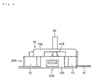
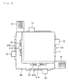
- a multi-directional input apparatus according to a first embodiment of the present invention comprises a box-like case 10 disposed on a mounting board, and variable resistors 20A and 20B as signal output means integrally provided on two side surfaces of the case 10 intersecting at right angles.
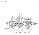
- variable resistors 20A and 20B accommodated in a body of the case 10 excluding the variable resistors 20A and 20B are a rod-like operating member 30 which is capable of being inclined in an arbitrary direction around its lower portion, upper and lower turning members 40A and 40B turnable by the operating member 30, a slider 50 for automatically returning the operating member 30 to its neutral position, and a spring 60.
- Straight-ahead sliders 70 and 70 are provided in the variable resistors 20A and 20B, respectively.
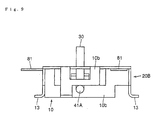
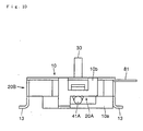
- the case 10 secured on the mounting board is of a two-piece structure comprising a combination of a lower case 10a formed into a box-shape of metal plate and a resin upper case lOb fitted to the lower case 10a from above.
- the metal lower case 10a includes a substantially rectangular bottom plate 11.
- the bottom plate 11 is provided at its central position with a downwardly projecting spherical concave portion 12 for supporting the lower turning member 40B.
- Apluralityof projectingpieces 13 projecting sideway are formed on four corners of the bottom plate 11. The projecting pieces 13 are intended to be fixed to a mounting board.
- the resin upper case 10b fitted to the lower case 10a includes a box-like body portion 14 whose lower surface is opened, and a pair of slider accommodating portions 15 and 15 integrally provided together with two side surface of the body portion 14 intersecting at right angles.
- the body portion 14 has a lid 16 provided with an opening 17 through which an upper portion of the operating member 30 is projected.
- the lid 16 is provided at its lower surface with an upwardly projecting spherical concave portion 18.
- the concave portion 18 is positioned around the opening 17.
- the pair of slider accommodating portions 15 and 15 are integrally formed into L-shapes along the two intersecting side surfaces of the body portion 14.
- the operating member 30 includes a rod body 31 having a circular cross section, a spherical support portion 32 integrally formed on a lower portion of the rod body 31, and an operating portion 33 integrally formed on a lower portion of the support portion 32.
- the support portion 32 is turnably fitted to the concave portion 18 formed on a lower surface of the lid of the body portion 14 of the upper case 10b.
- the upper turning member 40A is provided at its opposite ends with turning shafts 41A and 41A each having a circular cross section.
- the upper turning member 40A also includes a downwardly projecting arcuate operating portion 42A located between the turning shafts 41A and 41A.
- the operating portion 42A is provided with a long hole 43A extending toward a turning center axis as a guide hole for the operating member 30.
- An inner surface, i.e., an upper surface of the operating portion 42A is formed as an upwardly facing spherical concave surface into which the spherical support portion 32 of the operating member 30 is fitted.
- An outer surface, i.e., a lower surface of the operating portion 42 is formed as a downwardly facing spherical convex surface.
- one of the turning shafts 41B and 41B is integrally formed at its tip end surface with a gear 44.B.
- the gear 44B projects from a side of the body portion 14 of the upper case 10a, and is located above the slider accommodating portion 15.
- the gear 44B is a fan-like member having an arc surface directed downward, and the arc surface is formed with spur gear teeth 45B.
- the turning shafts 41B and 41B are connected to the arcuate portion 42B through shafts.
- Lower surfaces of the shafts are flat surfaces 46B and 46B against which a hoisting and lowering slider 50 resiliently abuts from below.
- the lower turning member 40B is assembled below the upper turning member 40A at right angles.
- the turning member 40B is provided at its opposite ends with turning shafts 41B and 41B each having a circular cross section.
- the turning member 40B also includes a downwardly projecting arcuate operating portion 42B located between the turning shafts 41B and 41B.
- the operating portion 42B is provided with a long hole 43B extended toward the turning center axis as a guide hole for the operating member 30.
- An inner surface, i.e., upper surface of the operating portion 42B is formed as an upwardly facing spherical concave surface into which the operating portion 42A of the turning member 40A is fitted.
- An outer surface, i.e., a lower surface of the operating portion 43B is formed as a downwardly facing spherical convex surface corresponding to the downwardly projecting spherical concave portion 12 provided on the bottom plate 11 of the case 10.
- one of the turning shafts 41B and 41B is integrally formed at its tip end surface with a gear 44B.
- the gear 44B projects from a side of the body portion 14 of the upper case 10a, and is located above the slider accommodating, portion 15.
- the gear 44B is a fan-likemember having an arc surface directed downward, and the arc surface is formed with spur gear teeth 45B.
- the turning shafts 41B and 41B are connected to the arcuate portion 42B through shafts.
- Lower surfaces of the shafts are flat surfaces 46B and 46B against which a hoisting and lowering slider 50 resiliently abuts from below.
- the flat surfaces 46B and 46B are flush with the flat surfaces 46A and 46A of the upper turning member 40A.
- the upper and lower turning members 40A and 40B are assembled into the case 10 in a state in which turning center axes thereof intersect at right angles on the same plane, and are turnably supported in the case 10.
- the support portion 32 is supported between the lid 16 of the case 10 and the operating portion 42A of the upper turning member 40A, so that the operating member 30 is turnably supported in the case 10.
- the operating portion 33 of the operating member 30 is inserted into the long holes 43A and 43B of the turning members 40A and 40B. With this design, the operating member 30 can incline in all peripheral directions around the support portion 32, and this inclining motion turns the turning members 40A and 40B.
- the hoisting and lowering slider 50 for automatically returning the operating member 30 to its neutral position is disposed such as to surround the operating portions 42A and 42B of the turning members 40A and 40B below the turning members 40A and 40B.
- the hoisting and lowering slider 50 is an annular body having a substantially rectangular outer peripheral surface fitted into the case 10 such that the hoisting and lowering slider 50 can be raised and lowered.
- the raising and lowering slider 50 is biased upward by a spring 60 compressed and accommodated between the hoisting and lowering slider 50 and the bottom plate 11 of the case 10.
- the hoisting and lowering slider 50 is brought into resilient surface-contact with the flat surfaces 46A and 46A of the turning member 40A and the flat surfaces 46B and 46B of the turning member 40B, thereby resiliently urging the turning members 40A and 40B at their neutral positions to resiliently hold the operating member 30 to its neutral position.
- the straight-ahead sliders 70 and 70 are accommodated in the slider accommodating portions 15 and 15 of the case 10, and an L-shaped flexible substrate 80 is also accommodated astride the slider accommodating portions 15 and 15.
- the straight-ahead sliders 70 and 70 can move in the horizontal direction along the two right-angled side surfaces of the body 14 of the case 10.
- Each straight-ahead slider 70 is formed at its upper surface with rack gear teeth 71, and downwardly directed fan-like gears 44A and 44B formed on portions of the turning members 40A and 40B are meshed with the teeth 71.
- the L-shaped flexible substrate 80 is disposed below the straight-ahead sliders 70 and 70 in the slider accommodating portions 15 and 15.
- the flexible substrate 80 is formed at its upper surface with a pair of resistance circuits corresponding to the straight-ahead sliders 70 and 70 by printing. Contacts mounted to lower surfaces of the straight-ahead sliders 70 and 70 are brought into contact with the pair of resistance circuits to constitute resistors. Opposite ends of the flexible substrate 80 project outward of the slider accommodating portions 15 and 15 as connecting portions 81 and 81 to be connected to a mounting substrate.
- the operating member 30 is inclined in the direction of the long hole 43B of the lower turning member 40B, the upper turning member 40A is turned and the variable resistor 20A is operated, and a signal corresponding to the operated amount is output. That is, in the variable resistor 20A, as the gear 44A is turned by the turning motion of the turning member 40A, the straight-ahead slider 70 moves, its contact slides on the corresponding resistance circuit on the flexible substrate 80, and a resistance value corresponding to the operated amount can be obtained.
- the lower turning member 40B is turned and the variable resistor 20B is operated, and a signal corresponding to the operated amount is output. That is, in the variable resistor 20B, as the gear 44B is turned by the turning motion of the turning member 40B, the straight-ahead slider 70 moves, its contact slides on the corresponding resistance circuit on the flexible substrate 80, and a resistance value corresponding to the operated amount can be obtained.
- the operating member 30 is operable in an arbitrary direction from a neutral position, such that a signal corresponding to the operated direction and the operated amount may be input to electrical or electronic equipment using the multi-directional input apparatus.
- the operating member 30 is supported in the case 10 by the spherical operating portion 32 provided on a portion of the operating member 30 in its axial direction without using a pin. Therefore, as compared with a case in which a pin is used, the length of the operating member 30 is shortened, and it is easy to reduce the apparatus in height.
- the spherical operating portion 32 is supported between the lid 16 of the case 10 and the operating portions 42A and 42B of the turning members 40A and 40B, the upper portion of the operating portion 32 is fitted into a concave portion 18 provided in the lower surface of the lid 16, and the lower half of the operating portion 32 is accommodated in the operating portions 42A and 42B of the turning members 40A and 40B.
- the center of the turning motion of the operating member 30 is located at the uppermost position possible in the case 10, and the lower space of both the shafts of the turning members 40A and 40B is enlarged.
- the hoisting and lowering slider 50 and the spring 60 are disposed around the operating portions 42A and 42B of the turning members 40A and 40B in the enlarged lower space. Therefore, increase in height of the apparatus caused by disposing the hoisting and lowering slider 50 and the spring 60 can be suppressed.
- the lower case 10a from which the operating portions 42A and 42B of the turning members 40A and 40B project is made of thin metal plate.
- the height of the apparatus can largely be reduced.
- variable resistors 20A and 20B as the signal output means are integrally formed in the apparatus, the number of parts is-small, and the cost is low as compared with an apparatus using external resistors.
- the multi-directional input apparatus of the second embodiment of the present invention is different from that of the first embodiment shown in Figs.1 to 5 in the support structure for the operating member 30. That is, in the multi-directional input apparatus of the first embodiment, the support portion 32 of the operating member 30 is sandwiched between the lid 16 of the case 10 and the operating portion 42A of the upper turning member 40, and the support portion 32 is prevented from falling out by the lid 16 of the case 10.
- an engaging portion 34 provided on a lower end of the operating member 30 engages the operating portion 42A of the upper turning member 40, the support portion 32 of the operating member 30 is turnably connected to the operating portion 42A of the upper turning member 40 so that the operating member 30 is prevented from falling out and from rotating around the axis.
- the support structure for the operating member 30 is not particularly limited.
- the multi-directional input apparatus of the third embodiment of the invention is different from the multi-directional input apparatus of the first embodiment of the invention mainly in that the operating portions 42A and 42B of the turning members 40A and 40B project upward, and space for accommodating the hoisting and lowering slider 50 and the spring 60 is secured above the operating portions 42A and 42B.
- the flexible substrate 80 is disposed above the straight-ahead slider 70.
- the case 10 comprises a resin lower case 10a forming a bottom plate, and a metal upper case 10b to be put on the lower case 10a from above.
- the slider accommodating portions 15 and 15 for accommodating the straight-ahead sliders 70 and 70 are integrally and continuously provided on the side of the resin lower case 10a.
- the turningmembers 40A and 40B include upwardly projecting arcuate operating portions 42A and 42B between opposite end turning shafts.
- the hoisting and lowering slider 50 is disposed above the opposite end shafts of the turning members 40A and 40B, and is biased downward by the spring 60 compressed and accommodated between the lid 16 of the case 10 and the hoisting and lowering slider 50. By this biasing operation, the hoisting and lowering slider 50 is brought into resilient surface-contact with the flat surfaces 46A and 46A formed on the upper surfaces of the opposite end shafts of the turning members 40A and 40B, thereby urging the operating member 30 and the turning members 40A and 40B to their neutral positions.
- the operating member 30 incluces an upwardly facing part-spherical first support portion 35 at one end of shaft 31, and a downwardly projecting part-spherical second support portion 36 below the first support portion 35.
- the first support portion 35 is fitted into the operating portion 42B of the lower turning member 40B from below, and also functions as a retaining means for the operating member 30.
- the second support portion 36 is supported on the bottom plate 11 of the case 10.
- the straight-ahead slider 70 is accommodated in the slider accommodating portion 15 of the case 10, and the flexible substrate 80 is located above the straight-ahead slider 70 and accommodated in the slider accommodating portion 15.
- the straight-ahead slider 70 is provided at its lower surface with rack gear teeth 71.
- Fan-like gears 44A and 44B are formed on portions of the corresponding turning members 40A and 40B such that the gears 44A and 44B are directed upward.
- the gears 44A and 44B are meshed with the teeth 71.
- a contact is mounted to an upper surface of the straight-ahead slider 70.
- the contact is in resilient contact with a resistance circuit formed on a lower surface of the flexible substrate 80.
- the operating member 30 is operable in an arbitrary direction from a neutral position, a signal -corresponding to the operated direction and the operated amount may be input to electrical or electronic equipment using the multi-directional input apparatus.
- the operating member 30 is supported in the case 10 by the part-spherical first support portion 35 and the second support portion 36 provided on a portion of the operating member 30 in its axial direction without using a pin. Therefore, as compared with a case in which a pin is used, the length of the operating member 30 is shortened, and it is easy to reduce the apparatus in height.
- first support portion 35 and the second support portion 36 are supported between the bottom plate 11 of the case 10 and the operating portion 42B of the upwardly projecting turning member 40B, and most of the first support portion 35 and the second support portion 36 are accommodated in the operating portion 42B of the turning member 40B.
- the turning center of the operating member 30 is located at a lower most position possible within the case 10 together with the turning centers of the turning members 40A and 40B, and the upper space of the opposite end shafts of the turning members 40A and 40B is enlarged.
- the hoisting and lowering slider 50 and the spring 60 are disposed in the enlarged upper space around the operating portions 42A and 42B of the turning members 40A and 40B. Therefore, increase in height of the apparatus caused by disposing the hoisting and lowering slider 50 and the spring 60 can be suppressed.
- the upper case lOb from which the operating portions 42A and 42B of the turning members 40A and 40B project is made of thin metal plate.
- the height of the apparatus can largely be reduced.
- variable resistors 20A and 20B as the signal output means are integrally formed in the apparatus, the number of-parts is small, and the cost is low as compared with an apparatus using external resistors.
- a multi-directional input apparatus is different from that of the third embodiment of the invention mainly in that a lower pushing-down switch is operated by the operating member 30 and in that the flexible substrate 80 is disposed below the straight-ahead slider 70 in the variable resistors 20A and 20B.
- the bottom plate 11 of the case 10 is provided with an opening 19 below the operating member 30.
- a snap plate 90 is mounted to a lower surface of the bottom plate 11 to bias the operating member 30 upward.
- the snap plate 90 includes a frame-like support portion 91 secured to a lower surface of the bottom plate 11, and a circular operating portion 92 provided inside the support portion 91 and supported by radial arms.
- the snap plate 90 is accommodated in a shallow concave portion provided in the lower surface. If the second support portion 36 of the operating member 30 is resiliently pushed upward through the opening 19 provided in the bottom plate 11, the push-down switch is constituted together with a contact formed on a surface of a mounting substrate.
- Opposite sides of the first support portion 35 of the operating member 30 are removed so as to prevent the operating member 30 from rotating around its axis.
- the straight-ahead sliders 70 and 70 are accommodated in the slider accommodating portions 15 and 15 of the case 10, and the flexible substrates 80 and 80 are located in the slider accommodating portions 15 and 15 below the straight-aheadsliders 70 and 70.
- the straight-ahead sliders 70 and 70 are provided at their inner side surfaces with concave portions 72 and 72 into which the gears 44A and 44B of the turning members 40A and 40B are inserted.
- the concave portions 72 and 72 are opened downward, and upper- surfaces of the concave portions 72 and 72 are provided with rack gear teeth 71 with which the upwardly directed gears 44A and 44B mesh.
- a contact 73 is mounted to a lower surface of each the straight-ahead slider 70, and the contact 73 comes into contact with a resistance circuit formed on an upper surface of the lower flexible substrate 80 from above.
- the operating member 30 is pushed down in the axial direction against the biasing force of the snap plate 90, thereby de forming the snap plate 90 downward.
- a contact formed on the surface of the mounting substrate is short-circuited.
- the flexible substrates 80 and 80 are disposed below the straight-ahead sliders 70 and 70, and the gears 44A and 44B are meshed with the straight-ahead sliders 70 and 70 from below, the height of each of the variable resistors 20A and 20B is suppressed. This structure is effective especially for a case 10 whose height is limited.
- the push-down switch is combined if necessary.
- the width of the apparatus can be largely reduced.
- the operating portions 42A and 42B of the turning members 40A and 40B project upward or downward, it is preferable that the operating portions 42A and 42B are disposed below the straight-ahead sliders 70 and 70 in terms of connection with the mounting substrate.
- the signal output means is integrally formed with the multi-directional input apparatus as the variable resistors 20A and 20B in each of the embodiments, the signal outputting means may be an external resistor, or an optical sensor or a magnetic sensor other than the resistor, and the kind of means is not limited.
- convex operating portions provided on axially intermediate portions of the upper and lower turning members are projected downward so as to operate the turning members, the returning mechanism is disposed below the turning members around the projecting operating portions, and the operating member is provided at its portion in its axial direction with a support portion having a large diameter located above the turning member so as to turnably support the operating member in the case .
- the support portion of the operating member is turnably disposed between a lid of the case and the operating portion of the upper turning member, the height of the apparatus can effectively be suppressed.
- convex operating portions provided on axially intermediate portions of the upper and lower turning members are projected upward so as to operate the turning members, the returning mechanism is disposed above the turning member around the projecting operating portions, and the operating member is provided at its portion in its axial direction with a support portion having a large diameter located below the turning member so as to turnably support the operating member in the case.
- the support portion of the operating member is turnably disposed between the operating portion of the lower turning member and a bottomplate of the case, the height of the apparatus can effectively be suppressed.
- the operating member is capable of moving in its axial direction and a snap plate constituting the push-down switch is mounted to a lower surface of the case. With this structure, the operating feeling when the push-down switch is also used can be stabilized.
Landscapes
- Physics & Mathematics (AREA)
- General Physics & Mathematics (AREA)
- Engineering & Computer Science (AREA)
- Automation & Control Theory (AREA)
- Switches With Compound Operations (AREA)
- Mechanical Control Devices (AREA)
Applications Claiming Priority (2)
| Application Number | Priority Date | Filing Date | Title |
|---|---|---|---|
| JP2000034015 | 2000-02-10 | ||
| JP2000034015A JP3725389B2 (ja) | 2000-02-10 | 2000-02-10 | 多方向入力装置 |
Publications (2)
| Publication Number | Publication Date |
|---|---|
| EP1124171A2 true EP1124171A2 (fr) | 2001-08-16 |
| EP1124171A3 EP1124171A3 (fr) | 2006-04-05 |
Family
ID=18558415
Family Applications (1)
| Application Number | Title | Priority Date | Filing Date |
|---|---|---|---|
| EP01301196A Withdrawn EP1124171A3 (fr) | 2000-02-10 | 2001-02-12 | Dispositif d'entrée multidirectionnel |
Country Status (6)
| Country | Link |
|---|---|
| US (1) | US6509535B2 (fr) |
| EP (1) | EP1124171A3 (fr) |
| JP (1) | JP3725389B2 (fr) |
| KR (1) | KR100420239B1 (fr) |
| CN (1) | CN1268999C (fr) |
| TW (1) | TW480508B (fr) |
Families Citing this family (17)
| Publication number | Priority date | Publication date | Assignee | Title |
|---|---|---|---|---|
| US7071918B2 (en) * | 2000-01-28 | 2006-07-04 | Hosiden Corporation | Volume-integral type multi directional input apparatus |
| EP1184776A4 (fr) * | 2000-01-28 | 2005-11-23 | Hosiden Corp | Dispositif integre multidirectionnel de commande de volume |
| JP4238085B2 (ja) * | 2003-07-25 | 2009-03-11 | アルプス電気株式会社 | 多方向スイッチ |
| US20090264384A1 (en) * | 2004-11-01 | 2009-10-22 | Nuada, Inc. | Indole, benzimidazole, and benzolactam boronic acid compounds, analogs thereof and methods of use thereof |
| JP4832317B2 (ja) * | 2007-01-11 | 2011-12-07 | アルプス電気株式会社 | 複合操作型入力装置 |
| US8164009B2 (en) * | 2007-04-13 | 2012-04-24 | Autonetworks Technologies, Ltd. | Control knob which operates multiple systems |
| KR200450632Y1 (ko) * | 2008-04-25 | 2010-10-18 | 동관 카이후아 일렉트로닉스 코., 엘티디. | 조합식 요동형 터치스위치 |
| JP4939571B2 (ja) * | 2009-05-20 | 2012-05-30 | ホシデン株式会社 | 多方向入力装置 |
| JP5768578B2 (ja) * | 2011-08-08 | 2015-08-26 | ヤマハ株式会社 | 操作子装置 |
| JP1520351S (fr) * | 2014-04-14 | 2015-03-30 | ||
| JP6209575B2 (ja) * | 2015-04-24 | 2017-10-04 | 任天堂株式会社 | 多方向入力装置 |
| JP6414703B2 (ja) * | 2015-11-18 | 2018-10-31 | 株式会社坂本電機製作所 | ジョイスティック |
| JP7235630B2 (ja) * | 2019-09-25 | 2023-03-08 | ホシデン株式会社 | 多方向入力装置 |
| CN116583811A (zh) * | 2020-11-05 | 2023-08-11 | 阿尔卑斯阿尔派株式会社 | 操作装置 |
| CN112490051B (zh) * | 2020-11-19 | 2025-07-22 | 深圳市致尚科技股份有限公司 | 多方向输入装置和游戏机 |
| CN112490053B (zh) * | 2020-11-19 | 2024-07-02 | 深圳市致尚科技股份有限公司 | 多方向输入装置和游戏机 |
| CN118197845B (zh) * | 2024-05-17 | 2024-08-06 | 宁波普瑞均胜汽车电子有限公司 | 微行程开关及汽车 |
Citations (3)
| Publication number | Priority date | Publication date | Assignee | Title |
|---|---|---|---|---|
| JPH0519925Y2 (fr) | 1988-11-14 | 1993-05-25 | ||
| JPH0727608Y2 (ja) | 1990-05-21 | 1995-06-21 | アルプス電気株式会社 | 多方向入力装置 |
| JPH10283885A (ja) | 1997-04-10 | 1998-10-23 | Teikoku Tsushin Kogyo Co Ltd | 多方向揺動型電子部品 |
Family Cites Families (23)
| Publication number | Priority date | Publication date | Assignee | Title |
|---|---|---|---|---|
| DE1947739A1 (de) * | 1969-09-20 | 1971-04-01 | Licentia Gmbh | Kreuzknueppelmechanik mit Potentiometern |
| US4459578A (en) * | 1983-01-13 | 1984-07-10 | Atari, Inc. | Finger control joystick utilizing Hall effect |
| US4489304A (en) * | 1983-07-22 | 1984-12-18 | Hayes Charles L | Spring disconnect mechanism for self centering multiple axis analog control stick |
| US4587510A (en) * | 1983-10-19 | 1986-05-06 | Wico Corporation | Analog joystick controller |
| US5107080A (en) * | 1989-12-01 | 1992-04-21 | Massachusetts Institute Of Technology | Multiple degree of freedom damped hand controls |
| US5113714A (en) * | 1991-02-20 | 1992-05-19 | The United States Of America As Represented By The Administrator Of The National Aeronautics & Space Administration | User friendly joystick |
| US5286024A (en) * | 1991-03-20 | 1994-02-15 | Atari Games Corporation | System for sensing the position of a joystick |
| US5773773A (en) * | 1993-11-22 | 1998-06-30 | Chrysler Corporation | Joystick with detent mechanism for tactile feedback centering |
| JP2916867B2 (ja) * | 1994-03-07 | 1999-07-05 | アルプス電気株式会社 | 多方向入力スイッチ |
| US5491462A (en) * | 1994-02-22 | 1996-02-13 | Wico Corporation | Joystick controller |
| JP3221254B2 (ja) * | 1994-10-14 | 2001-10-22 | 松下電器産業株式会社 | 多方向操作スイッチ |
| WO1996038810A1 (fr) * | 1995-06-02 | 1996-12-05 | Gerhard Wergen | Element analogique de commande |
| US5589854A (en) * | 1995-06-22 | 1996-12-31 | Tsai; Ming-Chang | Touching feedback device |
| JP3484276B2 (ja) * | 1995-11-10 | 2004-01-06 | 任天堂株式会社 | 電子部品のジョイスティック型操作機構 |
| GB2313432B (en) * | 1995-11-10 | 2000-06-21 | Nintendo Co Ltd | Joystick device |
| JPH1012098A (ja) * | 1996-06-26 | 1998-01-16 | Matsushita Electric Ind Co Ltd | 多方向操作スイッチおよびこれを用いた多方向操作装置 |
| JP2913277B2 (ja) * | 1996-09-02 | 1999-06-28 | アルプス電気株式会社 | 多方向入力スイッチ |
| KR200167212Y1 (ko) * | 1997-03-27 | 2000-03-02 | 오재민 | 조이스틱 |
| JP2996930B2 (ja) * | 1997-04-04 | 2000-01-11 | 三和電子株式会社 | ジョイスティックコントローラー |
| JP3506885B2 (ja) * | 1997-08-22 | 2004-03-15 | ホシデン株式会社 | アナログジョイスティック |
| JP3752389B2 (ja) * | 1998-10-05 | 2006-03-08 | アルプス電気株式会社 | 多方向入力装置 |
| JP3730439B2 (ja) * | 1999-04-22 | 2006-01-05 | アルプス電気株式会社 | 多方向入力装置 |
| JP3769153B2 (ja) * | 1999-09-14 | 2006-04-19 | ホシデン株式会社 | 多方向入力装置 |
-
2000
- 2000-02-10 JP JP2000034015A patent/JP3725389B2/ja not_active Expired - Fee Related
- 2000-10-05 TW TW089120797A patent/TW480508B/zh not_active IP Right Cessation
-
2001
- 2001-01-30 KR KR10-2001-0004200A patent/KR100420239B1/ko not_active Expired - Fee Related
- 2001-02-08 CN CNB01111326XA patent/CN1268999C/zh not_active Expired - Fee Related
- 2001-02-09 US US09/779,698 patent/US6509535B2/en not_active Expired - Fee Related
- 2001-02-12 EP EP01301196A patent/EP1124171A3/fr not_active Withdrawn
Patent Citations (3)
| Publication number | Priority date | Publication date | Assignee | Title |
|---|---|---|---|---|
| JPH0519925Y2 (fr) | 1988-11-14 | 1993-05-25 | ||
| JPH0727608Y2 (ja) | 1990-05-21 | 1995-06-21 | アルプス電気株式会社 | 多方向入力装置 |
| JPH10283885A (ja) | 1997-04-10 | 1998-10-23 | Teikoku Tsushin Kogyo Co Ltd | 多方向揺動型電子部品 |
Also Published As
| Publication number | Publication date |
|---|---|
| EP1124171A3 (fr) | 2006-04-05 |
| KR100420239B1 (ko) | 2004-03-02 |
| US20010020574A1 (en) | 2001-09-13 |
| JP2001229782A (ja) | 2001-08-24 |
| HK1037242A1 (en) | 2002-02-01 |
| TW480508B (en) | 2002-03-21 |
| US6509535B2 (en) | 2003-01-21 |
| KR20010082024A (ko) | 2001-08-29 |
| CN1309340A (zh) | 2001-08-22 |
| JP3725389B2 (ja) | 2005-12-07 |
| CN1268999C (zh) | 2006-08-09 |
Similar Documents
| Publication | Publication Date | Title |
|---|---|---|
| EP1146530B1 (fr) | Dispositif d'entree multidirectionnel | |
| US6509535B2 (en) | Multi directional input apparatus | |
| US6353430B2 (en) | Gimbal mounted joy stick with z-axis switch | |
| CN101286426B (zh) | 多方向输入装置 | |
| US20090008233A1 (en) | Compound operation input device | |
| US6504115B2 (en) | Multidirectional input device | |
| EP1126354B1 (fr) | Dispositif d'entree multidirectionnel | |
| US20050000783A1 (en) | Multi-directional slide switch | |
| KR100548946B1 (ko) | 밀어내림스위치 및 다방향 입력장치 | |
| US6670945B1 (en) | Volume integral type multi-directional input apparatus | |
| US20010020573A1 (en) | Multidirectional input device | |
| JP3763044B2 (ja) | 多方向スイッチ | |
| JPH0922642A (ja) | 多方向切換スイッチ | |
| JP3657469B2 (ja) | 多方向入力装置 | |
| JP4395857B2 (ja) | ボリューム一体型多方向入力装置 | |
| US20020186205A1 (en) | Volume-integral type multi directional input apparatus | |
| JP4913673B2 (ja) | 多方向操作スイッチ | |
| EP1566822B1 (fr) | Dispositif d'entrée multidirectionnel | |
| JP3108258B2 (ja) | X−y方向入力装置 | |
| JP2008137441A (ja) | シフトレバー装置 | |
| JP2008137440A (ja) | シフトレバー装置 | |
| JPH09213175A (ja) | 多方向操作スイッチ | |
| JPH02311923A (ja) | X―y方向入力装置 | |
| JPH058641U (ja) | X−y方向入力装置 | |
| JP2001109572A (ja) | 座標入力装置 |
Legal Events
| Date | Code | Title | Description |
|---|---|---|---|
| PUAI | Public reference made under article 153(3) epc to a published international application that has entered the european phase |
Free format text: ORIGINAL CODE: 0009012 |
|
| AK | Designated contracting states |
Kind code of ref document: A2 Designated state(s): AT BE CH CY DE DK ES FI FR GB GR IE IT LI LU MC NL PT SE TR |
|
| AX | Request for extension of the european patent |
Free format text: AL;LT;LV;MK;RO;SI |
|
| PUAL | Search report despatched |
Free format text: ORIGINAL CODE: 0009013 |
|
| AK | Designated contracting states |
Kind code of ref document: A3 Designated state(s): AT BE CH CY DE DK ES FI FR GB GR IE IT LI LU MC NL PT SE TR |
|
| AX | Request for extension of the european patent |
Extension state: AL LT LV MK RO SI |
|
| 17P | Request for examination filed |
Effective date: 20060522 |
|
| 17Q | First examination report despatched |
Effective date: 20060814 |
|
| AKX | Designation fees paid |
Designated state(s): DE FI FR GB SE |
|
| STAA | Information on the status of an ep patent application or granted ep patent |
Free format text: STATUS: THE APPLICATION IS DEEMED TO BE WITHDRAWN |
|
| 18D | Application deemed to be withdrawn |
Effective date: 20101101 |