EP1124227A2 - Tête de lecture optique, dispositif pour détecter une inclinaison, procédé pour détecter une inclinaison, et appareil de disque optique - Google Patents
Tête de lecture optique, dispositif pour détecter une inclinaison, procédé pour détecter une inclinaison, et appareil de disque optique Download PDFInfo
- Publication number
- EP1124227A2 EP1124227A2 EP01102608A EP01102608A EP1124227A2 EP 1124227 A2 EP1124227 A2 EP 1124227A2 EP 01102608 A EP01102608 A EP 01102608A EP 01102608 A EP01102608 A EP 01102608A EP 1124227 A2 EP1124227 A2 EP 1124227A2
- Authority
- EP
- European Patent Office
- Prior art keywords
- optical disk
- beams
- order diffraction
- laser
- phase distribution
- Prior art date
- Legal status (The legal status is an assumption and is not a legal conclusion. Google has not performed a legal analysis and makes no representation as to the accuracy of the status listed.)
- Granted
Links
Images




Classifications
-
- G—PHYSICS
- G11—INFORMATION STORAGE
- G11B—INFORMATION STORAGE BASED ON RELATIVE MOVEMENT BETWEEN RECORD CARRIER AND TRANSDUCER
- G11B7/00—Recording or reproducing by optical means, e.g. recording using a thermal beam of optical radiation by modifying optical properties or the physical structure, reproducing using an optical beam at lower power by sensing optical properties; Record carriers therefor
- G11B7/08—Disposition or mounting of heads or light sources relatively to record carriers
- G11B7/09—Disposition or mounting of heads or light sources relatively to record carriers with provision for moving the light beam or focus plane for the purpose of maintaining alignment of the light beam relative to the record carrier during transducing operation, e.g. to compensate for surface irregularities of the latter or for track following
- G11B7/095—Disposition or mounting of heads or light sources relatively to record carriers with provision for moving the light beam or focus plane for the purpose of maintaining alignment of the light beam relative to the record carrier during transducing operation, e.g. to compensate for surface irregularities of the latter or for track following specially adapted for discs, e.g. for compensation of eccentricity or wobble
-
- G—PHYSICS
- G11—INFORMATION STORAGE
- G11B—INFORMATION STORAGE BASED ON RELATIVE MOVEMENT BETWEEN RECORD CARRIER AND TRANSDUCER
- G11B7/00—Recording or reproducing by optical means, e.g. recording using a thermal beam of optical radiation by modifying optical properties or the physical structure, reproducing using an optical beam at lower power by sensing optical properties; Record carriers therefor
- G11B7/12—Heads, e.g. forming of the optical beam spot or modulation of the optical beam
- G11B7/13—Optical detectors therefor
- G11B7/131—Arrangement of detectors in a multiple array
-
- G—PHYSICS
- G11—INFORMATION STORAGE
- G11B—INFORMATION STORAGE BASED ON RELATIVE MOVEMENT BETWEEN RECORD CARRIER AND TRANSDUCER
- G11B7/00—Recording or reproducing by optical means, e.g. recording using a thermal beam of optical radiation by modifying optical properties or the physical structure, reproducing using an optical beam at lower power by sensing optical properties; Record carriers therefor
- G11B7/08—Disposition or mounting of heads or light sources relatively to record carriers
- G11B7/09—Disposition or mounting of heads or light sources relatively to record carriers with provision for moving the light beam or focus plane for the purpose of maintaining alignment of the light beam relative to the record carrier during transducing operation, e.g. to compensate for surface irregularities of the latter or for track following
- G11B7/095—Disposition or mounting of heads or light sources relatively to record carriers with provision for moving the light beam or focus plane for the purpose of maintaining alignment of the light beam relative to the record carrier during transducing operation, e.g. to compensate for surface irregularities of the latter or for track following specially adapted for discs, e.g. for compensation of eccentricity or wobble
- G11B7/0956—Disposition or mounting of heads or light sources relatively to record carriers with provision for moving the light beam or focus plane for the purpose of maintaining alignment of the light beam relative to the record carrier during transducing operation, e.g. to compensate for surface irregularities of the latter or for track following specially adapted for discs, e.g. for compensation of eccentricity or wobble to compensate for tilt, skew, warp or inclination of the disc, i.e. maintain the optical axis at right angles to the disc
-
- G—PHYSICS
- G11—INFORMATION STORAGE
- G11B—INFORMATION STORAGE BASED ON RELATIVE MOVEMENT BETWEEN RECORD CARRIER AND TRANSDUCER
- G11B7/00—Recording or reproducing by optical means, e.g. recording using a thermal beam of optical radiation by modifying optical properties or the physical structure, reproducing using an optical beam at lower power by sensing optical properties; Record carriers therefor
- G11B7/12—Heads, e.g. forming of the optical beam spot or modulation of the optical beam
- G11B7/135—Means for guiding the beam from the source to the record carrier or from the record carrier to the detector
- G11B7/1353—Diffractive elements, e.g. holograms or gratings
Definitions
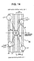
- said objective lens collects said main laser diffraction beam and exposes it to the track of said optical disk, and a distance from the center part of the optical spot of said main laser diffraction beam to the center part of the optical spots of said first and second sub laser diffraction beams in the disk radial direction is, where n is an integer of 0 or more, equal to or approximately equal to a (n/2 + 1/4) times of the pitch of said track or said track guide groove.
- the second optical pickup for example, it may be made the configuration which said wave front aberration is the coma aberration generated at a transparency substrate of said optical disk.
- said objective lens collects said main laser diffraction beam and exposes it to the track of said optical disk, and a distance from the center part of the optical spot of said main laser diffraction beam to the center part of the optical spots of said first and second sub laser diffraction beams in the disk radial direction is, where n is an integer of 0 or more, equal to or approximately equal to a (n/2 + 1/4) times of the pitch of said track or said track guide groove.
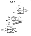
- the second sub light receiving portion 8S2 is divided two of the same or approximately same parts by the dividing line 8Sy2 and comprises two division areas 8E, 8F.
- the sub light spot SS2 is formed by (the reflected light of) the second sub laser beam from the cylindrical lens 7.
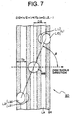
- the direction ⁇ is formed as the phase distribution, which are equal to or approximately equal to the phase distribution generated to the two sub light spots L1 and L2 by the tilt of the disk substrate in the disk radial direction, are given.
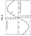
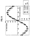
- Fig. 9 is a view for explaining the relationships between the tilt error signal TS and the tilting angle in the cases the tracking error exists (detrack state) and non-exists (on track state).
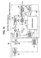
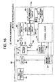
- the motor driving circuit 35 provides the driving power for the motor 30 to drive the motor 30.
- This motor driving circuit 35 may controls the rotation of the motor 30 by the PWM (Pulse Width Modulation) control and may controls it by the PLL (Phase Locked Loop) control.
- PWM Pulse Width Modulation
- PLL Phase Locked Loop
- This tilt error signal TS0 is expressed by the next equation (10).
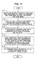
- the diffraction grating 9 of the optical pickup 51 diffracts the laser beam from the semiconductor laser 4 to generate the main laser beam including a 0th order diffraction beam and first and second sub laser beams each including +-first diffraction beams.
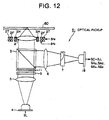
- the objective lens 2 collects laser beams (the main laser diffraction beam and the first to forth sub laser diffraction beams) from the diffraction grating 9 and 11 and provides them to the optical disk 80 to expose the laser beams on the optical disk 80.
- the objective lens 2 collects the main laser diffraction beam to expose the track of the optical disk 80.
- the main laser beam collected by the objective lens 2 are reflected at the optical disk 80, passes through the objective lens 2 again, and are provided for the photodeteotor 18 passing through the beam splitter 3, the collecting lens 6, and the cylindrical lens 7.
Landscapes
- Physics & Mathematics (AREA)
- Optics & Photonics (AREA)
- Optical Recording Or Reproduction (AREA)
Applications Claiming Priority (2)
| Application Number | Priority Date | Filing Date | Title |
|---|---|---|---|
| JP2000038263 | 2000-02-10 | ||
| JP2000038263 | 2000-02-10 |
Publications (3)
| Publication Number | Publication Date |
|---|---|
| EP1124227A2 true EP1124227A2 (fr) | 2001-08-16 |
| EP1124227A3 EP1124227A3 (fr) | 2003-01-29 |
| EP1124227B1 EP1124227B1 (fr) | 2007-07-04 |
Family
ID=18562025
Family Applications (1)
| Application Number | Title | Priority Date | Filing Date |
|---|---|---|---|
| EP01102608A Expired - Lifetime EP1124227B1 (fr) | 2000-02-10 | 2001-02-06 | Tête de lecture optique, dispositif pour détecter une inclinaison, procédé pour détecter une inclinaison, et appareil de disque optique |
Country Status (5)
| Country | Link |
|---|---|
| US (1) | US6829205B2 (fr) |
| EP (1) | EP1124227B1 (fr) |
| KR (1) | KR100747765B1 (fr) |
| DE (1) | DE60129178T2 (fr) |
| SG (1) | SG99885A1 (fr) |
Cited By (3)
| Publication number | Priority date | Publication date | Assignee | Title |
|---|---|---|---|---|
| WO2005036540A3 (fr) * | 2003-10-13 | 2005-06-02 | Koninkl Philips Electronics Nv | Procede et dispositif de compensation de l'inclinaison d'un support de donnees optiques |
| EP1804241A3 (fr) * | 2005-12-28 | 2007-11-21 | Kabushiki Kaisha Toshiba | Capture optique, appareil de disque optique, et procédé de détection d'inclinaison radiale |
| CN100487384C (zh) * | 2007-02-02 | 2009-05-13 | 清华大学深圳研究生院 | 光学头三维力矩器倾斜运动特性曲线的测试方法 |
Families Citing this family (12)
| Publication number | Priority date | Publication date | Assignee | Title |
|---|---|---|---|---|
| US6963522B2 (en) * | 2001-05-31 | 2005-11-08 | Nec Corporation | Optical head apparatus and optical information recording and reproducing apparatus |
| US20020181353A1 (en) * | 2001-05-31 | 2002-12-05 | Nec Corporation | Optical head apparatus and optical information recording and reproducing apparatus |
| US7068571B2 (en) * | 2001-10-18 | 2006-06-27 | Sanyo Electric Co., Ltd. | Optical recording apparatus and control method thereof |
| JP4098139B2 (ja) * | 2003-04-03 | 2008-06-11 | シャープ株式会社 | 光ピックアップ |
| JP3779705B2 (ja) * | 2003-08-13 | 2006-05-31 | Tdk株式会社 | 光ヘッド、ldモジュール、光記録再生装置及び光記録再生装置に用いる回折素子 |
| JP4158114B2 (ja) * | 2004-07-06 | 2008-10-01 | ソニー株式会社 | 光ピックアップ及びディスクドライブ装置 |
| JP4234109B2 (ja) * | 2004-10-18 | 2009-03-04 | 株式会社リコー | 光ピックアップ装置とこれを用いる情報記録装置 |
| TW200617924A (en) * | 2004-11-30 | 2006-06-01 | Lite On It Corp | Method and system for adjusting the servo control by monitoring spot status on photo detector of optical pickup head |
| KR100756042B1 (ko) | 2005-01-19 | 2007-09-07 | 삼성전자주식회사 | 회절소자 및 이를 포함하는 광픽업장치 |
| JP2006236514A (ja) * | 2005-02-28 | 2006-09-07 | Hitachi Media Electoronics Co Ltd | 回折格子、光ピックアップ及び光ディスク装置 |
| JP2008027513A (ja) * | 2006-07-20 | 2008-02-07 | Sony Corp | 光ディスク装置、トラッキングエラー信号生成回路、トラッキングエラー信号の補正方法、プログラム |
| JP5695410B2 (ja) * | 2010-12-20 | 2015-04-08 | 株式会社ミツトヨ | 角度検出装置およびその偏心量推定方法 |
Family Cites Families (14)
| Publication number | Priority date | Publication date | Assignee | Title |
|---|---|---|---|---|
| DE3009134A1 (de) * | 1980-03-10 | 1981-10-15 | Grünzweig + Hartmann Montage GmbH, 6700 Ludwigshafen | Waermedaemmung fuer den gewoelbten boden- und/oder deckelbereich eines druckbehaelters |
| DE68923833T2 (de) * | 1988-06-20 | 1996-06-13 | Mitsubishi Electric Corp | Optischer Kopf mit Kippkorrekturservomechanismus. |
| JPH0758559B2 (ja) * | 1988-09-02 | 1995-06-21 | シャープ株式会社 | 光ピックアップ装置 |
| JPH05101431A (ja) * | 1991-10-07 | 1993-04-23 | Sony Corp | 光デイスク再生装置 |
| JP3193105B2 (ja) * | 1992-02-29 | 2001-07-30 | 日本ビクター株式会社 | チルトエラー検出装置 |
| JPH07130022A (ja) * | 1993-11-08 | 1995-05-19 | Matsushita Electric Ind Co Ltd | 光ヘッド装置および光学素子 |
| EP0709834B1 (fr) * | 1994-10-31 | 2000-05-24 | Matsushita Electric Industrial Co., Ltd. | Capteur d'inclinaison, disque optique, et procédé de compensation d'inclinaison pour réaliser un contrôle de compensation d'inclinaison stable, et appareil les mettant en oeuvre |
| JP3447135B2 (ja) * | 1995-02-02 | 2003-09-16 | パイオニア株式会社 | 情報再生装置 |
| JP3176544B2 (ja) * | 1995-12-13 | 2001-06-18 | 株式会社日立製作所 | 光ディスク装置 |
| US5828634A (en) * | 1996-02-22 | 1998-10-27 | Ricoh Company, Ltd. | Optical disk tracking method and device for producing a tracking error signal and a track crossing signal |
| US6125087A (en) * | 1996-11-07 | 2000-09-26 | Hitachi, Ltd. | Optical pickup for optical disk apparatus |
| TW444201B (en) * | 1998-02-16 | 2001-07-01 | Hitachi Ltd | Optical head |
| JP3443668B2 (ja) * | 1998-04-30 | 2003-09-08 | 富士通株式会社 | 収差補正方法及び収差補正装置 |
| US6532202B1 (en) * | 1999-07-07 | 2003-03-11 | Matsushita Electric Industrial Co., Ltd. | Optical element, optical head and optical recording reproducing apparatus |
-
2001
- 2001-02-06 DE DE60129178T patent/DE60129178T2/de not_active Expired - Lifetime
- 2001-02-06 EP EP01102608A patent/EP1124227B1/fr not_active Expired - Lifetime
- 2001-02-08 KR KR1020010006166A patent/KR100747765B1/ko not_active Expired - Fee Related
- 2001-02-09 SG SG200100704A patent/SG99885A1/en unknown
- 2001-02-09 US US09/779,608 patent/US6829205B2/en not_active Expired - Fee Related
Cited By (3)
| Publication number | Priority date | Publication date | Assignee | Title |
|---|---|---|---|---|
| WO2005036540A3 (fr) * | 2003-10-13 | 2005-06-02 | Koninkl Philips Electronics Nv | Procede et dispositif de compensation de l'inclinaison d'un support de donnees optiques |
| EP1804241A3 (fr) * | 2005-12-28 | 2007-11-21 | Kabushiki Kaisha Toshiba | Capture optique, appareil de disque optique, et procédé de détection d'inclinaison radiale |
| CN100487384C (zh) * | 2007-02-02 | 2009-05-13 | 清华大学深圳研究生院 | 光学头三维力矩器倾斜运动特性曲线的测试方法 |
Also Published As
| Publication number | Publication date |
|---|---|
| EP1124227B1 (fr) | 2007-07-04 |
| KR20010082074A (ko) | 2001-08-29 |
| US6829205B2 (en) | 2004-12-07 |
| KR100747765B1 (ko) | 2007-08-08 |
| EP1124227A3 (fr) | 2003-01-29 |
| US20010046194A1 (en) | 2001-11-29 |
| SG99885A1 (en) | 2003-11-27 |
| DE60129178D1 (de) | 2007-08-16 |
| DE60129178T2 (de) | 2008-03-13 |
Similar Documents
| Publication | Publication Date | Title |
|---|---|---|
| US7558170B2 (en) | Optical pick-up head, optical information apparatus, and optical information reproducing method | |
| US7480216B2 (en) | Optical information recording apparatus | |
| JP3200171B2 (ja) | 光ディスクプレーヤ | |
| EP1124227B1 (fr) | Tête de lecture optique, dispositif pour détecter une inclinaison, procédé pour détecter une inclinaison, et appareil de disque optique | |
| JP2000182254A (ja) | ピックアップ装置 | |
| JP2002025091A (ja) | 回折格子、光ピックアップ、誤差信号検出装置および誤差信号検出方法 | |
| JPH1031826A (ja) | 光ピックアップにおけるコマ収差補正方法及び装置 | |
| EP1826757A2 (fr) | Dispositif à tête de lecture optique, et procédé et appareil pour la reproduction d'un support de stockage optique | |
| US7298676B2 (en) | Optical pickup apparatus having optical detection area for compensating for tracking error offset | |
| US6822934B2 (en) | Optical disc apparatus for finding a tracking error for an optical disk | |
| US20050094509A1 (en) | Optical head and optical information recording/reproducing apparatus using same | |
| JP3918006B2 (ja) | サーボ機能を有するホログラフィックrom再生機 | |
| KR100717020B1 (ko) | 기록층의 두께 변화에 따른 구면 수차를 탐지하고 보상하는광픽업 장치 | |
| US20020018434A1 (en) | An Astigmatism Generating Device To Remove Comma Aberration And Spherical Aberration | |
| CN1073733C (zh) | 用于高密度记录/再现的光拾取装置 | |
| EP1113426B1 (fr) | Tête optique, appareil de lecture de disque et méthode pour détecter le signal de traversée de piste | |
| JP4465893B2 (ja) | チルト検出装置、チルト検出方法、および、光ディスク装置 | |
| JP4153195B2 (ja) | ランド/グルーブ判別方法及び光記録再生機器 | |
| US6577565B1 (en) | Optical pickup for performing recording or reading operation on recording medium having prepits | |
| JP2000057608A (ja) | 光ピックアップ、情報再生装置及び情報記録装置 | |
| EP1804241A2 (fr) | Capture optique, appareil de disque optique, et procédé de détection d'inclinaison radiale | |
| JP2001229571A (ja) | 回折格子、光ピックアップ、チルト検出装置およびチルト検出方法 | |
| KR20020073609A (ko) | 광픽업 장치 | |
| JPH02201743A (ja) | 光ディスク装置における焦点制御信号検出方式 | |
| KR19990049995A (ko) | 광조절 액정소자를 이용한 듀얼 포커스 광픽업장치 |
Legal Events
| Date | Code | Title | Description |
|---|---|---|---|
| PUAI | Public reference made under article 153(3) epc to a published international application that has entered the european phase |
Free format text: ORIGINAL CODE: 0009012 |
|
| AK | Designated contracting states |
Kind code of ref document: A2 Designated state(s): AT BE CH CY DE DK ES FI FR GB GR IE IT LI LU MC NL PT SE TR |
|
| AX | Request for extension of the european patent |
Free format text: AL;LT;LV;MK;RO;SI |
|
| PUAL | Search report despatched |
Free format text: ORIGINAL CODE: 0009013 |
|
| AK | Designated contracting states |
Designated state(s): AT BE CH CY DE DK ES FI FR GB GR IE IT LI LU MC NL PT SE TR |
|
| AX | Request for extension of the european patent |
Extension state: AL LT LV MK RO SI |
|
| 17P | Request for examination filed |
Effective date: 20030318 |
|
| AKX | Designation fees paid |
Designated state(s): DE FR GB |
|
| GRAP | Despatch of communication of intention to grant a patent |
Free format text: ORIGINAL CODE: EPIDOSNIGR1 |
|
| GRAS | Grant fee paid |
Free format text: ORIGINAL CODE: EPIDOSNIGR3 |
|
| GRAA | (expected) grant |
Free format text: ORIGINAL CODE: 0009210 |
|
| AK | Designated contracting states |
Kind code of ref document: B1 Designated state(s): DE FR GB |
|
| REG | Reference to a national code |
Ref country code: GB Ref legal event code: FG4D |
|
| REF | Corresponds to: |
Ref document number: 60129178 Country of ref document: DE Date of ref document: 20070816 Kind code of ref document: P |
|
| ET | Fr: translation filed | ||
| PLBE | No opposition filed within time limit |
Free format text: ORIGINAL CODE: 0009261 |
|
| STAA | Information on the status of an ep patent application or granted ep patent |
Free format text: STATUS: NO OPPOSITION FILED WITHIN TIME LIMIT |
|
| 26N | No opposition filed |
Effective date: 20080407 |
|
| REG | Reference to a national code |
Ref country code: GB Ref legal event code: 746 Effective date: 20091130 |
|
| PGFP | Annual fee paid to national office [announced via postgrant information from national office to epo] |
Ref country code: FR Payment date: 20110302 Year of fee payment: 11 Ref country code: DE Payment date: 20110218 Year of fee payment: 11 |
|
| PGFP | Annual fee paid to national office [announced via postgrant information from national office to epo] |
Ref country code: GB Payment date: 20110217 Year of fee payment: 11 |
|
| GBPC | Gb: european patent ceased through non-payment of renewal fee |
Effective date: 20120206 |
|
| REG | Reference to a national code |
Ref country code: FR Ref legal event code: ST Effective date: 20121031 |
|
| REG | Reference to a national code |
Ref country code: DE Ref legal event code: R119 Ref document number: 60129178 Country of ref document: DE Effective date: 20120901 |
|
| PG25 | Lapsed in a contracting state [announced via postgrant information from national office to epo] |
Ref country code: GB Free format text: LAPSE BECAUSE OF NON-PAYMENT OF DUE FEES Effective date: 20120206 Ref country code: FR Free format text: LAPSE BECAUSE OF NON-PAYMENT OF DUE FEES Effective date: 20120229 |
|
| PG25 | Lapsed in a contracting state [announced via postgrant information from national office to epo] |
Ref country code: DE Free format text: LAPSE BECAUSE OF NON-PAYMENT OF DUE FEES Effective date: 20120901 |