EP1124277A2 - Lithium Sekundärbatterie - Google Patents
Lithium Sekundärbatterie Download PDFInfo
- Publication number
- EP1124277A2 EP1124277A2 EP01301104A EP01301104A EP1124277A2 EP 1124277 A2 EP1124277 A2 EP 1124277A2 EP 01301104 A EP01301104 A EP 01301104A EP 01301104 A EP01301104 A EP 01301104A EP 1124277 A2 EP1124277 A2 EP 1124277A2
- Authority
- EP
- European Patent Office
- Prior art keywords
- electrode
- battery
- secondary battery
- lithium
- lithium secondary
- Prior art date
- Legal status (The legal status is an assumption and is not a legal conclusion. Google has not performed a legal analysis and makes no representation as to the accuracy of the status listed.)
- Withdrawn
Links
- 229910052744 lithium Inorganic materials 0.000 title claims abstract description 31
- WHXSMMKQMYFTQS-UHFFFAOYSA-N Lithium Chemical compound [Li] WHXSMMKQMYFTQS-UHFFFAOYSA-N 0.000 title claims abstract description 27
- XLYOFNOQVPJJNP-UHFFFAOYSA-N water Substances O XLYOFNOQVPJJNP-UHFFFAOYSA-N 0.000 claims abstract description 51
- 239000008151 electrolyte solution Substances 0.000 claims abstract description 28
- 230000001186 cumulative effect Effects 0.000 claims abstract description 8
- 239000003792 electrolyte Substances 0.000 claims abstract description 8
- 150000002642 lithium compounds Chemical class 0.000 claims abstract description 8
- 238000010030 laminating Methods 0.000 claims abstract description 6
- 238000004804 winding Methods 0.000 claims abstract description 5
- 239000013543 active substance Substances 0.000 claims description 13
- 238000010438 heat treatment Methods 0.000 claims description 12
- 229910052596 spinel Inorganic materials 0.000 claims description 9
- 239000011029 spinel Substances 0.000 claims description 9
- -1 lithium hexafluorophosphate Chemical compound 0.000 claims description 8
- 229910002102 lithium manganese oxide Inorganic materials 0.000 claims description 7
- VLXXBCXTUVRROQ-UHFFFAOYSA-N lithium;oxido-oxo-(oxomanganiooxy)manganese Chemical compound [Li+].[O-][Mn](=O)O[Mn]=O VLXXBCXTUVRROQ-UHFFFAOYSA-N 0.000 claims description 7
- 239000011572 manganese Substances 0.000 claims description 6
- 229910052748 manganese Inorganic materials 0.000 claims description 4
- PWHULOQIROXLJO-UHFFFAOYSA-N Manganese Chemical compound [Mn] PWHULOQIROXLJO-UHFFFAOYSA-N 0.000 claims description 2
- 239000011357 graphitized carbon fiber Substances 0.000 claims description 2
- 238000007599 discharging Methods 0.000 abstract description 32
- 230000006866 deterioration Effects 0.000 abstract description 7
- 239000007772 electrode material Substances 0.000 description 15
- 238000004519 manufacturing process Methods 0.000 description 12
- 238000000034 method Methods 0.000 description 12
- 239000002002 slurry Substances 0.000 description 10
- 239000000758 substrate Substances 0.000 description 9
- 239000000463 material Substances 0.000 description 8
- 239000011888 foil Substances 0.000 description 7
- 238000005259 measurement Methods 0.000 description 7
- 239000002904 solvent Substances 0.000 description 7
- OKKJLVBELUTLKV-UHFFFAOYSA-N Methanol Chemical compound OC OKKJLVBELUTLKV-UHFFFAOYSA-N 0.000 description 6
- 239000004698 Polyethylene Substances 0.000 description 6
- 238000001035 drying Methods 0.000 description 6
- 238000012360 testing method Methods 0.000 description 6
- OKTJSMMVPCPJKN-UHFFFAOYSA-N Carbon Chemical compound [C] OKTJSMMVPCPJKN-UHFFFAOYSA-N 0.000 description 5
- 239000011230 binding agent Substances 0.000 description 5
- 238000006243 chemical reaction Methods 0.000 description 5
- 229910001416 lithium ion Inorganic materials 0.000 description 5
- 229910052751 metal Inorganic materials 0.000 description 5
- 239000002184 metal Substances 0.000 description 5
- 239000004743 Polypropylene Substances 0.000 description 4
- 230000004075 alteration Effects 0.000 description 4
- 229910052782 aluminium Inorganic materials 0.000 description 4
- 150000001875 compounds Chemical class 0.000 description 4
- 239000003960 organic solvent Substances 0.000 description 4
- 239000000843 powder Substances 0.000 description 4
- 230000008569 process Effects 0.000 description 4
- WEVYAHXRMPXWCK-UHFFFAOYSA-N Acetonitrile Chemical compound CC#N WEVYAHXRMPXWCK-UHFFFAOYSA-N 0.000 description 3
- OIFBSDVPJOWBCH-UHFFFAOYSA-N Diethyl carbonate Chemical compound CCOC(=O)OCC OIFBSDVPJOWBCH-UHFFFAOYSA-N 0.000 description 3
- KMTRUDSVKNLOMY-UHFFFAOYSA-N Ethylene carbonate Chemical compound O=C1OCCO1 KMTRUDSVKNLOMY-UHFFFAOYSA-N 0.000 description 3
- 230000015572 biosynthetic process Effects 0.000 description 3
- 239000003575 carbonaceous material Substances 0.000 description 3
- 238000011156 evaluation Methods 0.000 description 3
- 239000000203 mixture Substances 0.000 description 3
- PXHVJJICTQNCMI-UHFFFAOYSA-N nickel Substances [Ni] PXHVJJICTQNCMI-UHFFFAOYSA-N 0.000 description 3
- 229910052718 tin Inorganic materials 0.000 description 3
- 239000010936 titanium Substances 0.000 description 3
- 229910052719 titanium Inorganic materials 0.000 description 3
- YEJRWHAVMIAJKC-UHFFFAOYSA-N 4-Butyrolactone Chemical compound O=C1CCCO1 YEJRWHAVMIAJKC-UHFFFAOYSA-N 0.000 description 2
- RYGMFSIKBFXOCR-UHFFFAOYSA-N Copper Chemical compound [Cu] RYGMFSIKBFXOCR-UHFFFAOYSA-N 0.000 description 2
- HBBGRARXTFLTSG-UHFFFAOYSA-N Lithium ion Chemical compound [Li+] HBBGRARXTFLTSG-UHFFFAOYSA-N 0.000 description 2
- RAHZWNYVWXNFOC-UHFFFAOYSA-N Sulphur dioxide Chemical compound O=S=O RAHZWNYVWXNFOC-UHFFFAOYSA-N 0.000 description 2
- WYURNTSHIVDZCO-UHFFFAOYSA-N Tetrahydrofuran Chemical compound C1CCOC1 WYURNTSHIVDZCO-UHFFFAOYSA-N 0.000 description 2
- 239000006230 acetylene black Substances 0.000 description 2
- XAGFODPZIPBFFR-UHFFFAOYSA-N aluminium Chemical compound [Al] XAGFODPZIPBFFR-UHFFFAOYSA-N 0.000 description 2
- 229910052787 antimony Inorganic materials 0.000 description 2
- 229910052796 boron Inorganic materials 0.000 description 2
- 239000003153 chemical reaction reagent Substances 0.000 description 2
- 239000003795 chemical substances by application Substances 0.000 description 2
- 238000004891 communication Methods 0.000 description 2
- 239000000470 constituent Substances 0.000 description 2
- 239000011889 copper foil Substances 0.000 description 2
- 238000005260 corrosion Methods 0.000 description 2
- 230000007797 corrosion Effects 0.000 description 2
- 230000002950 deficient Effects 0.000 description 2
- 230000000694 effects Effects 0.000 description 2
- 238000003487 electrochemical reaction Methods 0.000 description 2
- 229910021385 hard carbon Inorganic materials 0.000 description 2
- 229910052742 iron Inorganic materials 0.000 description 2
- XEEYBQQBJWHFJM-UHFFFAOYSA-N iron Substances [Fe] XEEYBQQBJWHFJM-UHFFFAOYSA-N 0.000 description 2
- 229910000625 lithium cobalt oxide Inorganic materials 0.000 description 2
- BFZPBUKRYWOWDV-UHFFFAOYSA-N lithium;oxido(oxo)cobalt Chemical compound [Li+].[O-][Co]=O BFZPBUKRYWOWDV-UHFFFAOYSA-N 0.000 description 2
- 229910052749 magnesium Inorganic materials 0.000 description 2
- 239000011777 magnesium Substances 0.000 description 2
- 239000012046 mixed solvent Substances 0.000 description 2
- 229910052750 molybdenum Inorganic materials 0.000 description 2
- 229910052759 nickel Inorganic materials 0.000 description 2
- 229910052758 niobium Inorganic materials 0.000 description 2
- 238000005457 optimization Methods 0.000 description 2
- 229910052698 phosphorus Inorganic materials 0.000 description 2
- 238000002360 preparation method Methods 0.000 description 2
- RUOJZAUFBMNUDX-UHFFFAOYSA-N propylene carbonate Chemical compound CC1COC(=O)O1 RUOJZAUFBMNUDX-UHFFFAOYSA-N 0.000 description 2
- 239000002994 raw material Substances 0.000 description 2
- 229910052710 silicon Inorganic materials 0.000 description 2
- 239000000243 solution Substances 0.000 description 2
- 238000001179 sorption measurement Methods 0.000 description 2
- 239000000126 substance Substances 0.000 description 2
- 238000004448 titration Methods 0.000 description 2
- 229910052721 tungsten Inorganic materials 0.000 description 2
- 229910052720 vanadium Inorganic materials 0.000 description 2
- 238000003466 welding Methods 0.000 description 2
- 229910052725 zinc Inorganic materials 0.000 description 2
- 239000011701 zinc Substances 0.000 description 2
- XVMSFILGAMDHEY-UHFFFAOYSA-N 6-(4-aminophenyl)sulfonylpyridin-3-amine Chemical compound C1=CC(N)=CC=C1S(=O)(=O)C1=CC=C(N)C=N1 XVMSFILGAMDHEY-UHFFFAOYSA-N 0.000 description 1
- KRHYYFGTRYWZRS-UHFFFAOYSA-M Fluoride anion Chemical compound [F-] KRHYYFGTRYWZRS-UHFFFAOYSA-M 0.000 description 1
- 229910013068 LiMxMn2-xO4 Inorganic materials 0.000 description 1
- 229910013064 LiMxMn2−xO4 Inorganic materials 0.000 description 1
- RTAQQCXQSZGOHL-UHFFFAOYSA-N Titanium Chemical compound [Ti] RTAQQCXQSZGOHL-UHFFFAOYSA-N 0.000 description 1
- 230000002378 acidificating effect Effects 0.000 description 1
- 230000004913 activation Effects 0.000 description 1
- 239000011149 active material Substances 0.000 description 1
- 238000003928 amperometric titration Methods 0.000 description 1
- 229910021383 artificial graphite Inorganic materials 0.000 description 1
- 239000012298 atmosphere Substances 0.000 description 1
- QVGXLLKOCUKJST-UHFFFAOYSA-N atomic oxygen Chemical compound [O] QVGXLLKOCUKJST-UHFFFAOYSA-N 0.000 description 1
- 229910052799 carbon Inorganic materials 0.000 description 1
- 150000004651 carbonic acid esters Chemical class 0.000 description 1
- 150000001768 cations Chemical class 0.000 description 1
- 229910052804 chromium Inorganic materials 0.000 description 1
- 238000000576 coating method Methods 0.000 description 1
- 239000000356 contaminant Substances 0.000 description 1
- 238000011109 contamination Methods 0.000 description 1
- 230000001276 controlling effect Effects 0.000 description 1
- 238000007796 conventional method Methods 0.000 description 1
- 239000013078 crystal Substances 0.000 description 1
- IEJIGPNLZYLLBP-UHFFFAOYSA-N dimethyl carbonate Chemical compound COC(=O)OC IEJIGPNLZYLLBP-UHFFFAOYSA-N 0.000 description 1
- 239000007789 gas Substances 0.000 description 1
- 229910002804 graphite Inorganic materials 0.000 description 1
- 239000010439 graphite Substances 0.000 description 1
- 230000007062 hydrolysis Effects 0.000 description 1
- 238000006460 hydrolysis reaction Methods 0.000 description 1
- 239000011261 inert gas Substances 0.000 description 1
- PNDPGZBMCMUPRI-UHFFFAOYSA-N iodine Chemical compound II PNDPGZBMCMUPRI-UHFFFAOYSA-N 0.000 description 1
- 238000005304 joining Methods 0.000 description 1
- MHCFAGZWMAWTNR-UHFFFAOYSA-M lithium perchlorate Chemical compound [Li+].[O-]Cl(=O)(=O)=O MHCFAGZWMAWTNR-UHFFFAOYSA-M 0.000 description 1
- CJYZTOPVWURGAI-UHFFFAOYSA-N lithium;manganese;manganese(3+);oxygen(2-) Chemical compound [Li+].[O-2].[O-2].[O-2].[O-2].[Mn].[Mn+3] CJYZTOPVWURGAI-UHFFFAOYSA-N 0.000 description 1
- VROAXDSNYPAOBJ-UHFFFAOYSA-N lithium;oxido(oxo)nickel Chemical compound [Li+].[O-][Ni]=O VROAXDSNYPAOBJ-UHFFFAOYSA-N 0.000 description 1
- 230000014759 maintenance of location Effects 0.000 description 1
- 230000007246 mechanism Effects 0.000 description 1
- 229910021382 natural graphite Inorganic materials 0.000 description 1
- 239000007773 negative electrode material Substances 0.000 description 1
- 229910052760 oxygen Inorganic materials 0.000 description 1
- 239000001301 oxygen Substances 0.000 description 1
- 230000035515 penetration Effects 0.000 description 1
- 229920000573 polyethylene Polymers 0.000 description 1
- 229920000642 polymer Polymers 0.000 description 1
- 229920001155 polypropylene Polymers 0.000 description 1
- 239000007774 positive electrode material Substances 0.000 description 1
- 238000003918 potentiometric titration Methods 0.000 description 1
- 238000003825 pressing Methods 0.000 description 1
- 230000001105 regulatory effect Effects 0.000 description 1
- 239000012488 sample solution Substances 0.000 description 1
- 238000007789 sealing Methods 0.000 description 1
- 229910021384 soft carbon Inorganic materials 0.000 description 1
- 239000006104 solid solution Substances 0.000 description 1
- 238000003860 storage Methods 0.000 description 1
- 238000006467 substitution reaction Methods 0.000 description 1
- 229910052715 tantalum Inorganic materials 0.000 description 1
- YLQBMQCUIZJEEH-UHFFFAOYSA-N tetrahydrofuran Natural products C=1C=COC=1 YLQBMQCUIZJEEH-UHFFFAOYSA-N 0.000 description 1
Images

Classifications
-
- H—ELECTRICITY
- H01—ELECTRIC ELEMENTS
- H01M—PROCESSES OR MEANS, e.g. BATTERIES, FOR THE DIRECT CONVERSION OF CHEMICAL ENERGY INTO ELECTRICAL ENERGY
- H01M10/00—Secondary cells; Manufacture thereof
- H01M10/05—Accumulators with non-aqueous electrolyte
- H01M10/052—Li-accumulators
- H01M10/0525—Rocking-chair batteries, i.e. batteries with lithium insertion or intercalation in both electrodes; Lithium-ion batteries
-
- H—ELECTRICITY
- H01—ELECTRIC ELEMENTS
- H01M—PROCESSES OR MEANS, e.g. BATTERIES, FOR THE DIRECT CONVERSION OF CHEMICAL ENERGY INTO ELECTRICAL ENERGY
- H01M4/00—Electrodes
- H01M4/02—Electrodes composed of, or comprising, active material
- H01M4/36—Selection of substances as active materials, active masses, active liquids
- H01M4/48—Selection of substances as active materials, active masses, active liquids of inorganic oxides or hydroxides
- H01M4/485—Selection of substances as active materials, active masses, active liquids of inorganic oxides or hydroxides of mixed oxides or hydroxides for inserting or intercalating light metals, e.g. LiTi2O4 or LiTi2OxFy
-
- H—ELECTRICITY
- H01—ELECTRIC ELEMENTS
- H01M—PROCESSES OR MEANS, e.g. BATTERIES, FOR THE DIRECT CONVERSION OF CHEMICAL ENERGY INTO ELECTRICAL ENERGY
- H01M4/00—Electrodes
- H01M4/02—Electrodes composed of, or comprising, active material
- H01M4/36—Selection of substances as active materials, active masses, active liquids
- H01M4/48—Selection of substances as active materials, active masses, active liquids of inorganic oxides or hydroxides
- H01M4/50—Selection of substances as active materials, active masses, active liquids of inorganic oxides or hydroxides of manganese
- H01M4/505—Selection of substances as active materials, active masses, active liquids of inorganic oxides or hydroxides of manganese of mixed oxides or hydroxides containing manganese for inserting or intercalating light metals, e.g. LiMn2O4 or LiMn2OxFy
-
- H—ELECTRICITY
- H01—ELECTRIC ELEMENTS
- H01M—PROCESSES OR MEANS, e.g. BATTERIES, FOR THE DIRECT CONVERSION OF CHEMICAL ENERGY INTO ELECTRICAL ENERGY
- H01M4/00—Electrodes
- H01M4/02—Electrodes composed of, or comprising, active material
- H01M4/36—Selection of substances as active materials, active masses, active liquids
- H01M4/58—Selection of substances as active materials, active masses, active liquids of inorganic compounds other than oxides or hydroxides, e.g. sulfides, selenides, tellurides, halogenides or LiCoFy; of polyanionic structures, e.g. phosphates, silicates or borates
- H01M4/583—Carbonaceous material, e.g. graphite-intercalation compounds or CFx
- H01M4/587—Carbonaceous material, e.g. graphite-intercalation compounds or CFx for inserting or intercalating light metals
-
- H—ELECTRICITY
- H01—ELECTRIC ELEMENTS
- H01M—PROCESSES OR MEANS, e.g. BATTERIES, FOR THE DIRECT CONVERSION OF CHEMICAL ENERGY INTO ELECTRICAL ENERGY
- H01M6/00—Primary cells; Manufacture thereof
- H01M6/04—Cells with aqueous electrolyte
- H01M6/06—Dry cells, i.e. cells wherein the electrolyte is rendered non-fluid
- H01M6/10—Dry cells, i.e. cells wherein the electrolyte is rendered non-fluid with wound or folded electrodes
-
- H—ELECTRICITY
- H01—ELECTRIC ELEMENTS
- H01M—PROCESSES OR MEANS, e.g. BATTERIES, FOR THE DIRECT CONVERSION OF CHEMICAL ENERGY INTO ELECTRICAL ENERGY
- H01M6/00—Primary cells; Manufacture thereof
- H01M6/14—Cells with non-aqueous electrolyte
- H01M6/16—Cells with non-aqueous electrolyte with organic electrolyte
- H01M6/162—Cells with non-aqueous electrolyte with organic electrolyte characterised by the electrolyte
-
- Y—GENERAL TAGGING OF NEW TECHNOLOGICAL DEVELOPMENTS; GENERAL TAGGING OF CROSS-SECTIONAL TECHNOLOGIES SPANNING OVER SEVERAL SECTIONS OF THE IPC; TECHNICAL SUBJECTS COVERED BY FORMER USPC CROSS-REFERENCE ART COLLECTIONS [XRACs] AND DIGESTS
- Y02—TECHNOLOGIES OR APPLICATIONS FOR MITIGATION OR ADAPTATION AGAINST CLIMATE CHANGE
- Y02E—REDUCTION OF GREENHOUSE GAS [GHG] EMISSIONS, RELATED TO ENERGY GENERATION, TRANSMISSION OR DISTRIBUTION
- Y02E60/00—Enabling technologies; Technologies with a potential or indirect contribution to GHG emissions mitigation
- Y02E60/10—Energy storage using batteries
-
- Y—GENERAL TAGGING OF NEW TECHNOLOGICAL DEVELOPMENTS; GENERAL TAGGING OF CROSS-SECTIONAL TECHNOLOGIES SPANNING OVER SEVERAL SECTIONS OF THE IPC; TECHNICAL SUBJECTS COVERED BY FORMER USPC CROSS-REFERENCE ART COLLECTIONS [XRACs] AND DIGESTS
- Y02—TECHNOLOGIES OR APPLICATIONS FOR MITIGATION OR ADAPTATION AGAINST CLIMATE CHANGE
- Y02P—CLIMATE CHANGE MITIGATION TECHNOLOGIES IN THE PRODUCTION OR PROCESSING OF GOODS
- Y02P70/00—Climate change mitigation technologies in the production process for final industrial or consumer products
- Y02P70/50—Manufacturing or production processes characterised by the final manufactured product
-
- Y—GENERAL TAGGING OF NEW TECHNOLOGICAL DEVELOPMENTS; GENERAL TAGGING OF CROSS-SECTIONAL TECHNOLOGIES SPANNING OVER SEVERAL SECTIONS OF THE IPC; TECHNICAL SUBJECTS COVERED BY FORMER USPC CROSS-REFERENCE ART COLLECTIONS [XRACs] AND DIGESTS
- Y02—TECHNOLOGIES OR APPLICATIONS FOR MITIGATION OR ADAPTATION AGAINST CLIMATE CHANGE
- Y02T—CLIMATE CHANGE MITIGATION TECHNOLOGIES RELATED TO TRANSPORTATION
- Y02T10/00—Road transport of goods or passengers
- Y02T10/60—Other road transportation technologies with climate change mitigation effect
- Y02T10/70—Energy storage systems for electromobility, e.g. batteries
Definitions
- the present invention relates to a lithium secondary battery in which the deterioration of battery properties attributed to water released from both of a positive electrode and negative electrode and existing in the non-aqueous electrolytic solution packed in the battery is suppressed.
- a lithium secondary battery in recent years , has widely been employed as a secondary battery chargeable and dischargeable, small in size, having a high energy density, and capable of functioning as an electric power source of electronic appliances such as portable communication appliances, notebook type personal computers and the like. Further, in the situation where people have been paying much attention to resource saving and energy saving for the international protection of global environments, the lithium secondary battery is expected to be used, in the automobile industry, as a battery for driving a motor of an electric automobile and a hybrid electric automobile and, in the electric power industry, as a means for efficiently utilizing electric power by storing night time electric power. It is, therefore, urgently required to develop a lithium secondary battery with a large capacity and practically suitable for the above applications.
- a lithium transition metal compound oxide or the like is used as a positive electrode active material and a carbonaceous material such as hard carbon and graphite is used as a negative electrode active material.
- a lithium secondary battery comprising such materials has a reaction potential as high as about 4.1 V and therefore, it is impossible to use an aqueous electrolytic solution, which has been used for a conventional secondary battery.
- a non-aqueous electrolytic solution comprising an organic solvent and a lithium compound dissolved therein as a lithium ion (Li + ) electrolyte is, therefore, used as a non-aqueous electrolytic solution of a lithium secondary battery.
- Electrodes are manufactured in strict environments, regarding a battery with a large capacity and produced by winding or laminating electrode plates manufactured by applying electrode active materials to current collector substrates, the moisture adsorbed in the electrode active materials or the like cannot completely be removed only by a normal drying process.
- an electrode active material is applied to a current collector substrate and formed into a prescribed shape such as a tape-like shape and during the forming process, the electrode active material is mixed with an organic solvent or water to be in the slurry or paste state to be used.
- the electrode active material is mixed with an organic solvent or water to be in the slurry or paste state to be used.
- the water control in the produced slurry is imperfect, the probability of adsorption of water in the electrode active material is extremely high.
- a lithium secondary battery comprising an electrode unit produced by winding or laminating a positive electrode and a negative electrode via a separator, and a non-aqueous electrolytic solution containing a lithium compound as an electrolyte, wherein the cumulative concentration of water (H 2 O) released from both of the positive electrode and the negative electrode in relation to the weight of the electrode unit, exclusive of current collectors, is suppressed to 5,000 ppm or lower in the case of heating both electrodes at 25 to 200°C and/or to 1,500 ppm or lower in the case of heating the electrodes at 200 to 300°C.
- H 2 O water
- the lithium compound to be used preferably for such a lithium secondary battery of the present invention is lithium hexafluorophosphate.
- a material to be employed for the electrode active material is not specifically limited and in the case where lithium manganese oxide containing lithium and manganese as main components and having a cubic system spinel structure is used as the electrode active material, the internal resistance of the battery can be suppressed low.
- a highly graphitized carbon fiber is preferably used as the negative electrode active substance.
- the present invention is suitably applied to a large scale battery having a battery capacity of 2 Ah or more.
- a lithium secondary battery of the present invention is suitably used as an electric power source for driving a motor of an electric automobile or a hybrid electric automobile in which large current discharge is frequently caused.
- Fig. 1 is a perspective view illustrating the structure of a rolled type electrode unit.
- Fig. 2 is a perspective view illustrating the structure of a laminated type electrode unit.
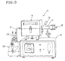
- Fig. 3 is an illustration of the apparatus for measuring the concentration of water released from an electrode plate.
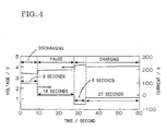
- Fig. 4 is a graph illustrating the charging and discharging pattern in the cycle test. Detailed Description of the Preferred Embodiments
- a lithium secondary battery of the present invention is one comprising a non-aqueous electrolytic solution containing a lithium compound dissolved therein to provide lithium ion (Li + ) as an electrolyte. Consequently, the materials for other components and the battery structure are not at all restricted. Hereinafter, description will be given at first on the main members constituting the battery and on their structures.
- One structure of an electrode unit, which may be compared to a heart part, of a lithium secondary battery is a single cell structure comprising a positive electrode active substance and a negative electrode active substance press-molded into a disk-like shape and a separator interposed between them and such a structure is of a coin type battery with a small capacity.
- a rolled type electrode unit 1 is constituted of a positive electrode 2, a negative electrode 3, and a separator 4 of a porous polymer which are so rolled around a core 13 as to interpose the separator between the positive electrode 2 and the negative electrode 3 for keeping them from direct contact with each other.
- the positive electrode 2 and the negative electrode 3 (hereinafter referred to as the electrodes 2, 3) are connected separately to at least one electrode lead 5, 6 and can be connected separately to a plurality of electrode leads 5, 6 to lower the resistance of the current collectors.
- Another structure of the electrode unit includes a laminated type obtained by laminating a plurality of electrode units each applicable for a single cell type coin battery.
- a laminated type electrode unit 7 is obtained by reciprocally laminating positive electrodes 8 and negative electrodes 9 both with prescribed shapes while interposing separators 10 between them and connecting at least one electrode lead 11, 12 respectively to each one of electrodes 8, 9.
- the materials used for the electrodes 8, 9, the production methods therefor, and the like are same as those of the electrodes 2, 3 in the rolled type electrode unit 1.
- the positive electrode 2 is produced by applying a positive electrode active substance to both sides of a current collector substrate.
- a metal foil such as an aluminum foil, a titanium foil, and the like excellent in the corrosion resistance to cathodic electrochemical reactions is preferably used for the current collector substrate and further besides the foil, a punched metal or a mesh may also be employed.
- Preferable compounds to be used for the positive electrode active substance are lithium transition metal compound oxides such as lithium manganese oxide (LiMn 2 O 4 ), lithium cobalt oxide (LiCoO 2 ), lithium nickel oxide (LiNiO 2 ), and the like and it is preferable to add, as a conductivity-improving agent, a fine carbon powder such as acetylene black or the like to these compounds.
- lithium transition metal compound oxides such as lithium manganese oxide (LiMn 2 O 4 ), lithium cobalt oxide (LiCoO 2 ), lithium nickel oxide (LiNiO 2 ), and the like and it is preferable to add, as a conductivity-improving agent, a fine carbon powder such as acetylene black or the like to these compounds.
- LiMn 2 O 4 spinel a lithium manganese oxide having a cubic system spinel structure
- the LiMn 2 O 4 spinel is not limited to such a spinel oxide with stoichiometric composition alone and also preferable to be used is a spinel obtained by partly substituting Mn of the spinel with one or more elements and having a general formula; LiM x Mn 2-x O 4 (M denotes a substituent element and x denotes the ratio of the substitution).
- substituent element M there can be mentioned Li, Fe, Mn, Ni, Mg, Zn, B, Al, Co, Cr, Si, Ti, Sn, P, V, Sb, Nb, Ta, Mo and W.
- the substituent element M is an element forming a solid-solution in the LiMn 2 O 4 theoretically in the form of monovalent Li; bivalent Fe, Mn, Ni, Mg or Zn; trivalent B, Al, Co, or Cr; tetravalent Si, Ti, and Sn, pentavalent P, V, Sb, Nb, or Ta; or hexavalent Mo or W cation.
- Co and Sn are bivalent; Fe, Sb, and Ti trivalent; Mn trivalent or tetravalent; and Cr tetravalent or hexavalent.
- the respective substituent elements M may sometimes exist in a mixed valency state and the quantity of oxygen may, therefore, not necessarily be 4 as in the case of the stoichiometric composition and may be deficient or excessive within a defined range as long as the crystal structure is maintained.
- the application of the positive electrode active substance is carried out by applying a slurry or a paste produced by adding a solvent, a binder, and the like to a positive electrode active substance powder to a current collector substrate by a roll coater method or the like and drying the resulting material, and then, based on necessity, pressing treatment or the like may be carried out.
- the negative electrode 3 can be produced in the same manner as for the positive electrode 2.
- a metal foil such as a copper foil, a nickel foil, and the like excellent in the corrosion resistance to anodic electrochemical reactions is preferably used for the current collector substrate of the negative electrode 3.
- the compounds to be used for the negative electrode active substance are amorphous carbonaceous material powder such as soft carbon and hard carbon, highly graphitized carbonaceous material powder such as synthetic graphite and natural graphite.
- the separator 4 it is preferable to use a three-layer structure comprising a microporous and Li + -permeable polyethylene film (PE film) and porous and Li + -permeable polypropylene films (PP films) sandwiching the PE film between them.
- PE film microporous and Li + -permeable polyethylene film
- PP films porous and Li + -permeable polypropylene films
- the PP films By sandwiching the PE film between PP films of a more softening point, the PP films retain the shape to prevent contact and short circuit between the positive electrode 2 and the negative electrode 3, to reliably suppress the battery reactions, and to secure the safety even when the PE film is softened.
- electrode leads 5, 6 are separately joined to a part of each electrodes 2, 3 in which no electrode active substance is applied and where each current collector substrate is exposed.
- the electrode leads 5, 6, it is preferable to use those made of foils of the same materials as those of the current collector substrates of the respective electrodes 2, 3.
- the joining of the electrode leads 5, 6 to the electrodes 2, 3 can be carried out by ultrasonic welding, spot welding or the like. In that case, as shown in Fig. 1, it is preferable to join electrode leads 5, 6 in a manner where one of the electrode leads of the respective electrodes is joined to one end face of the electrode unit 1, for the electrode leads 5, 6 can be kept from contact with each other.
- the produced electrode unit 1 is inserted into a battery case and held in a stable position while the electric communication of terminals for taking electric current out to the outside with electrode leads 5, 6 being reliably secured. After that, the electrode unit is impregnated with a non-aqueous electrolytic solution and then the battery case is sealed to produce a battery.
- the solvent are carbonic acid esters such as ethylene carbonate (EC), diethyl carbonate (DEC), dimethyl carbonate (DMC), propylene carbonate (PC), and the like; single solvents such as ⁇ -butyrolactone, tetrahydrofuran, acetonitrile, and the like; and their mixtures.
- carbonic acid esters such as ethylene carbonate (EC), diethyl carbonate (DEC), dimethyl carbonate (DMC), propylene carbonate (PC), and the like
- single solvents such as ⁇ -butyrolactone, tetrahydrofuran, acetonitrile, and the like; and their mixtures.
- a lithium compound to be dissolved in such a solvent i.e. an electrolyte
- a lithium complex fluoride such as lithium hexafluorophosphate (LiPF 6 ), lithium borofluoride (LiBF 4 ), and the like and a lithium halogen compound such as lithium perchlorate (LiClO 4 ) and the like.
- LiPF 6 lithium hexafluorophosphate
- LiBF 4 lithium borofluoride
- LiClO 4 lithium perchlorate
- the cumulative concentration of water released from both of the positive electrode and the negative electrode in relation to the weight of the electrode unit besides the current collectors is suppressed to 5,000 ppm or lower in the case of heating both electrodes at 25 to 200°C.
- the initial charging and discharging efficiency has been verified to be maintained high in the case where water concentration is suppressed to 5,000 ppm or lower when both electrode plates are heated at 25 to 200°C.
- the water to be released in this temperature range is supposed to be water released from the electrode plates in the stage in which the electrode plates are inserted into the battery case and the battery case is filled with the electrolytic solution and the water supposedly affects the initial charging and discharging efficiency.
- the SEI layer formation on the active material surface results from the water.
- the methods suitable to be employed as the method for suppressing the concentration of water released from both electrode plates to 5,000 ppm or lower at the time of heating at 25 to 200°C are (1) slurry preparation in the environment of a low humidity ( ⁇ 30% R.H.), (2) optimization of the drying temperature (>150°C) of coated bodies, and (3) rolled body production in the environment of a low humidity ( ⁇ 30% R.H.).
- the cumulative concentration of water released from both of the positive electrode and the negative electrode in relation to the weight of the electrode unit besides the current collectors is suppressed to 1,500 ppm or lower in the case of heating both electrodes at 200 to 300°C.
- the self-discharging efficiency and the cycle property have been verified to be maintained excellent.
- the water released in this temperature range is supposed to be water released from the electrode plates due to activation of water by electric reaction during repetition of charging and discharging and the water supposedly affects the self-discharge and cycle property deterioration in a middle to long period.
- the methods suitable to be employed as the method for suppressing the concentration of released water to 1,500 ppm or lower at the time of heating both electrode plates at 200 to 300°C are (1) slurry preparation in the environment of a low humidity ( ⁇ 30% R.H.), (2) optimization of the drying temperature (>150°C) of coated bodies, and (3) rolled body production in the environment of a low humidity ( ⁇ 30% R.H.).
- the increase of the temperature of the electrode plates means the observation of the water release from the electrode plates with the lapse of time and can correspondingly be considered as alteration of the battery properties with the lapse of time.
- that the temperature is increased owing to heating of the electrode plates at 25 to 200°C and at 200 to 300°C can be supposed to be causes of deterioration of battery properties for the middle and long periods from immediate after production of the battery.
- the electrodes in which the water concentration is regulated to the forgoing prescribed values or lower in the respective temperature ranges, a battery showing excellent battery properties immediate after the battery production and in a long duration can be produced.
- a single property i.e. the high initial charging and discharging efficiency, the excellent self-discharging efficiency, or the cycle property
- the Karl Fischer's method is preferably employed for the measurement of the concentration of water released from both of the positive electrode and the negative electrode.
- the measurement is carried out by putting both electrodes to be subjected to the measurement in an electric furnace 15 through a specimen setting inlet 16, increasing the temperature of the electrodes by a heating pipe 17 in the inert gas flow, and sending the released water to a measurement part 20 through a suction pipe 21.
- a non-aqueous electrolytic solution is dissolved or dispersed in methanol and the resulting sample solution is titrated with a reddish brown Karl Fischer's reagent, a reagent for water quantitative determination for the volumetric analysis, obtained by dissolving iodine, sulfur dioxide, and pyridine in methanol ordinarily at a molecular ratio of 1 : 3 : 10 and the measurement can be carried out by observing the alteration of the color of the reaction solution by a colorimetric titration, a potentiometric titration, or an amperometric titration.
- Each battery of examples 1 to 5 was produced by producing a positive electrode by applying a positive electrode substance slurry containing LiMn 2 O 4 spinel as a positive electrode active substance, acetylene black as a conductivity-improving agent in 4% by mass as an extrapolating ratio, a solvent, and a binder to both sides of a 20 ⁇ m thick aluminum foil to form about 100 ⁇ m thick coatings on both sides, producing a negative electrode by the same manner by applying a negative electrode active substance using a carbon powder to both sides of a 10 ⁇ m thick copper foil in about 80 ⁇ m thickness, producing a wound type electrode unit comprising the produced positive electrode and negative electrode, housing the obtained electrode unit in a battery case, and filling the resultant battery case with a non-aqueous electrolytic solution.
- Table 1 shows the results of evaluation of the initial charging and discharging efficiency, the self-discharging efficiency, and the cycle property of each of the foregoing examples.
- the electrodes of respective examples 1 to 5 were produced by the above described method using various electrode constituent members which were so adjusted as to cause the difference in the concentrations of water released from the respective electrodes.
- the other members and the testing environments were the same for all of the samples and the battery members were sufficiently dried immediate before the assembly of the respective batteries and there is eliminated the effect of such as water penetration from the outside of the batteries due to defective sealing of the batteries.
- a solution containing a mixed solvent of EC and DEC in the same volume and LiPF 6 as an electrolyte dissolved in the mixed solvent in 1 mol/l concentration was employed as a non-aqueous electrolytic solution.
- Charging and discharging of batteries were carried out, as shown in Table 2, in 9 steps.
- 0.5C is the discharge rate meaning performance of charging and discharging at 1 A electric current
- CH means the charging process
- DCH means the discharging process.
- the steps (1) to (9) were named step A to step I, respectively.
- the initial charging and discharging efficiency (%) was calculated based on the equation B/A ⁇ 100 and the self-discharging efficiency (%) was calculated based on the equation (1 - 2G/(D + 1))/3.
- Charging and discharging step Content capacity (1) A 0.5C CH (2) B 0.5C DCH (3) C 0.5C CH (4) D 0.5C DCH (5) E 0.5C CH (6) F Kept still for 3 days (7) G 0.5C DCH (8) H 0.5C CH (9) I 0.5C DCH
- the cycle test was carried out by assuming that the charging and discharging cycle shown in Fig. 4 is one cycle, and repeating the charging and discharging cycle. Evaluation was given as the discharging capacity retention ratio after repeating the charging and discharging cycles 20,000 times. Every cycle was carried out in a pattern in which batteries in charged state of 50% depth of discharge were discharged for 9 seconds at 100 A current equivalent to 10C (discharge rate), then put in pause for 18 seconds, after that further charged for 6 seconds at 70 A, successively charged for 27 seconds at 18 A, and finally put in 50% charged state again. In that case, the current value at the second time charging (18 A) was finely adjusted to suppress the difference of the depth of discharge in every cycle to the minimum.
- capacity measurement was properly carried out at 0.2C current intensity while setting the charge stopping voltage at 4.1 V and the discharge stopping voltage at 2.5 V and the relative discharging capacity was computed as a value calculated by dividing the battery capacity in the cycles at prescribed times by the initial battery capacity.
- the present invention has been described mainly on a case using a wound type electrode unit.
- the present invention is applicable independently of the structure of a battery and can be employed suitably for a battery with a large capacity in which water control is not easy during the production process.
- the capacity of present invention can suitably be employed for a battery having a capacity of 2 Ah or more and comprising wound type or laminated type electrode units 1, 7.
- a lithium secondary battery of the present invention is especially suitably used as a battery for driving a motor of an electric automobile or of a hybrid electric automobile which requires the battery to have a low internal resistance, an excellent charging and discharging efficiency and cycle property.
- the present invention restriction is posed in the cumulative concentration of water released from both of a positive electrode and a negative electrode and existing in the non-aqueous electrolytic solution packed in a battery. Consequently, the present invention is effective to improve the initial charging and discharging efficiency, the self-discharging efficiency, and the cycle property and to prolong the life of the battery.
Landscapes
- Chemical & Material Sciences (AREA)
- Engineering & Computer Science (AREA)
- Materials Engineering (AREA)
- Manufacturing & Machinery (AREA)
- Chemical Kinetics & Catalysis (AREA)
- Electrochemistry (AREA)
- General Chemical & Material Sciences (AREA)
- Secondary Cells (AREA)
- Battery Electrode And Active Subsutance (AREA)
- Arrangement Or Mounting Of Propulsion Units For Vehicles (AREA)
Applications Claiming Priority (2)
| Application Number | Priority Date | Filing Date | Title |
|---|---|---|---|
| JP2000032362A JP2001223030A (ja) | 2000-02-09 | 2000-02-09 | リチウム二次電池 |
| JP2000032362 | 2000-02-09 |
Publications (2)
| Publication Number | Publication Date |
|---|---|
| EP1124277A2 true EP1124277A2 (de) | 2001-08-16 |
| EP1124277A3 EP1124277A3 (de) | 2003-05-21 |
Family
ID=18556977
Family Applications (1)
| Application Number | Title | Priority Date | Filing Date |
|---|---|---|---|
| EP01301104A Withdrawn EP1124277A3 (de) | 2000-02-09 | 2001-02-08 | Lithium Sekundärbatterie |
Country Status (4)
| Country | Link |
|---|---|
| US (1) | US20010016291A1 (de) |
| EP (1) | EP1124277A3 (de) |
| JP (1) | JP2001223030A (de) |
| CA (1) | CA2333850A1 (de) |
Families Citing this family (16)
| Publication number | Priority date | Publication date | Assignee | Title |
|---|---|---|---|---|
| US6844977B2 (en) * | 2001-01-26 | 2005-01-18 | Ciena Corporation | Multi-channel optical filter |
| US7682739B2 (en) | 2004-05-12 | 2010-03-23 | Mitsui Mining & Smelting Co., Ltd. | Negative electrode for nonaqueous secondary battery and process of producing the same |
| JP3799049B2 (ja) | 2004-05-12 | 2006-07-19 | 三井金属鉱業株式会社 | 非水電解液二次電池用負極及びその製造方法 |
| JP5115781B2 (ja) * | 2006-10-23 | 2013-01-09 | トヨタ自動車株式会社 | リチウム二次電池およびその製造方法 |
| JP2008108463A (ja) * | 2006-10-23 | 2008-05-08 | Toyota Motor Corp | リチウム二次電池およびその製造方法 |
| JP5260887B2 (ja) * | 2007-05-09 | 2013-08-14 | パナソニック株式会社 | 非水電解質二次電池 |
| CN101405898B (zh) * | 2007-05-09 | 2012-01-25 | 松下电器产业株式会社 | 非水电解质二次电池 |
| JP2012204098A (ja) * | 2011-03-24 | 2012-10-22 | Mitsubishi Motors Corp | リチウムイオン二次電池の製造方法 |
| JP5784961B2 (ja) * | 2011-04-28 | 2015-09-24 | 国立大学法人高知大学 | 被覆活物質の製造方法 |
| US20140113175A1 (en) * | 2011-06-02 | 2014-04-24 | Panyi Zhang | High capacity lithium ion battery containing metallic conducting materials |
| US11024845B2 (en) * | 2012-04-16 | 2021-06-01 | Lg Chem, Ltd. | Moisture-limited electrode active material, moisture-limited electrode and lithium secondary battery comprising the same |
| JP5880964B2 (ja) * | 2012-06-28 | 2016-03-09 | トヨタ自動車株式会社 | 非水電解質二次電池 |
| WO2014038491A1 (ja) | 2012-09-06 | 2014-03-13 | 株式会社クレハ | 非水電解質二次電池負極用炭素質材料及びその製造方法 |
| JP6747297B2 (ja) * | 2014-10-31 | 2020-08-26 | 日本ゼオン株式会社 | 電気化学素子用電極の製造方法、電気化学素子用電極および電気化学素子 |
| WO2016097129A1 (en) * | 2014-12-18 | 2016-06-23 | Solvay Sa | Electrolyte composition comprising fluorinated carbonate, and battery comprising the same |
| JP6596826B2 (ja) | 2015-01-15 | 2019-10-30 | 株式会社デンソー | 電極及び非水電解質二次電池 |
Family Cites Families (6)
| Publication number | Priority date | Publication date | Assignee | Title |
|---|---|---|---|---|
| US3864168A (en) * | 1974-03-22 | 1975-02-04 | Yardney International Corp | Electrolytic cells incorporating water scavengers |
| DE3637146A1 (de) * | 1985-11-01 | 1987-05-07 | Nippon Telegraph & Telephone | Lithium-sekundaerbatterie |
| IT1218084B (it) * | 1988-06-16 | 1990-04-12 | Consiglio Nazionale Ricerche | Polimeri conduttori utilizzabili per la realizzazione di batterie completamente a secco |
| DE69838169T2 (de) * | 1997-05-27 | 2008-04-17 | Tdk Corp. | Verfahren zur herstellung einer elektrode für batterie mit nichtwässrigem elektrolyten |
| US6383688B1 (en) * | 1997-12-26 | 2002-05-07 | Tonen Corporation | Electrolyte for lithium cells and method of producing the same |
| JPH11260416A (ja) * | 1998-03-11 | 1999-09-24 | Ngk Insulators Ltd | リチウム二次電池 |
-
2000
- 2000-02-09 JP JP2000032362A patent/JP2001223030A/ja active Pending
-
2001
- 2001-01-26 US US09/770,725 patent/US20010016291A1/en not_active Abandoned
- 2001-02-01 CA CA002333850A patent/CA2333850A1/en not_active Abandoned
- 2001-02-08 EP EP01301104A patent/EP1124277A3/de not_active Withdrawn
Also Published As
| Publication number | Publication date |
|---|---|
| JP2001223030A (ja) | 2001-08-17 |
| CA2333850A1 (en) | 2001-08-09 |
| EP1124277A3 (de) | 2003-05-21 |
| US20010016291A1 (en) | 2001-08-23 |
Similar Documents
| Publication | Publication Date | Title |
|---|---|---|
| EP3343688B1 (de) | Verfahren zur herstellung einer batteriezelle mit einer referenzelektrode zur messung des relativen elektrodenpotenzials und damit hergestellte batteriezelle | |
| EP1124277A2 (de) | Lithium Sekundärbatterie | |
| JP4060562B2 (ja) | 電極体の評価方法 | |
| US7135253B2 (en) | High discharge current lithium secondary battery and method of manufacture | |
| KR101890031B1 (ko) | 비수 전해액 이차 전지 및 비수 전해액 이차 전지의 제조 방법 | |
| JP2001273927A (ja) | リチウム二次電池 | |
| EP2779284A1 (de) | Nichtwässrige Elektrolytbatterie | |
| US9337490B2 (en) | Lithium ion secondary battery | |
| US10897064B2 (en) | Nonaqueous electrolyte secondary cell including negative electrode active material made of amorphous-coated graphite and electrolytic solution including lithium fluorosulfonate | |
| EP4024559B1 (de) | Batteriezelle zur bewertung des lithiumfällungsverhaltens und verfahren zu deren herstellung | |
| JP2001283921A (ja) | リチウム二次電池 | |
| JP3594521B2 (ja) | リチウム二次電池の評価方法 | |
| JP2003123836A (ja) | リチウム二次電池 | |
| JP2001068153A (ja) | リチウム二次電池 | |
| KR101744382B1 (ko) | 이차전지용 전극 리드 및 이를 포함하는 이차전지 | |
| JP2002352862A (ja) | 電極体の評価方法及びそれを用いたリチウム二次電池、並びにその製造方法 | |
| JP2000260469A (ja) | リチウム二次電池 | |
| JP2002305035A (ja) | リチウム二次電池 | |
| JP2005116321A (ja) | リチウム二次電池及びその低温特性評価方法 | |
| JP2001223031A (ja) | リチウム二次電池 | |
| JP4040264B2 (ja) | 電極体の評価方法 | |
| JP2003197271A (ja) | リチウム二次電池の評価方法及びそれを用いたリチウム二次電池 | |
| JP2004214212A (ja) | リチウム二次電池 | |
| JP2003178812A (ja) | リチウム二次電池の評価方法及びそれを用いたリチウム二次電池 | |
| JP2001135302A (ja) | リチウム二次電池及びその作製方法 |
Legal Events
| Date | Code | Title | Description |
|---|---|---|---|
| PUAI | Public reference made under article 153(3) epc to a published international application that has entered the european phase |
Free format text: ORIGINAL CODE: 0009012 |
|
| AK | Designated contracting states |
Kind code of ref document: A2 Designated state(s): AT BE CH CY DE DK ES FI FR GB GR IE IT LI LU MC NL PT SE TR |
|
| AX | Request for extension of the european patent |
Free format text: AL;LT;LV;MK;RO;SI |
|
| PUAL | Search report despatched |
Free format text: ORIGINAL CODE: 0009013 |
|
| AK | Designated contracting states |
Designated state(s): AT BE CH CY DE DK ES FI FR GB GR IE IT LI LU MC NL PT SE TR |
|
| AX | Request for extension of the european patent |
Extension state: AL LT LV MK RO SI |
|
| 17P | Request for examination filed |
Effective date: 20030613 |
|
| AKX | Designation fees paid |
Designated state(s): AT BE CH CY DE DK ES FI FR GB GR IE IT LI LU MC NL PT SE TR |
|
| 17Q | First examination report despatched |
Effective date: 20070615 |
|
| STAA | Information on the status of an ep patent application or granted ep patent |
Free format text: STATUS: THE APPLICATION IS DEEMED TO BE WITHDRAWN |
|
| 18D | Application deemed to be withdrawn |
Effective date: 20090829 |